LOGOMAT DS03 User manual

Rev. 1.00
USER
MANUAL

USER MANUAL DS03 REV.1.0
This document is a property of LOGOMAT s.r.l.
No part of this document may be reproduced without the prior explicit permission of LOGOMAT s.r.l. Page. 2of 45
A.C.E. s.r.l.
Via A. Costa n°61
40067 Rastignano - Bologna (Italia)
Tel. 051 6260573
Fax 051 6260573
E-mail: LOGOMAT@LOGOMATsrl.com
www.LOGOMATsrl.com

USER MANUAL DS03 REV.1.0
This document is a property of LOGOMAT s.r.l.
No part of this document may be reproduced without the prior explicit permission of LOGOMAT s.r.l. Page. 3of 45
Contents
1. Introduction ......................................................................................................................... 4
1. GENERAL DESCRIPTION OF HARDWARE.............................................................................5
1.1. Components............................................................................................................................................... 5
1.2. Central unit technical features DS03......................................................................................................... 6
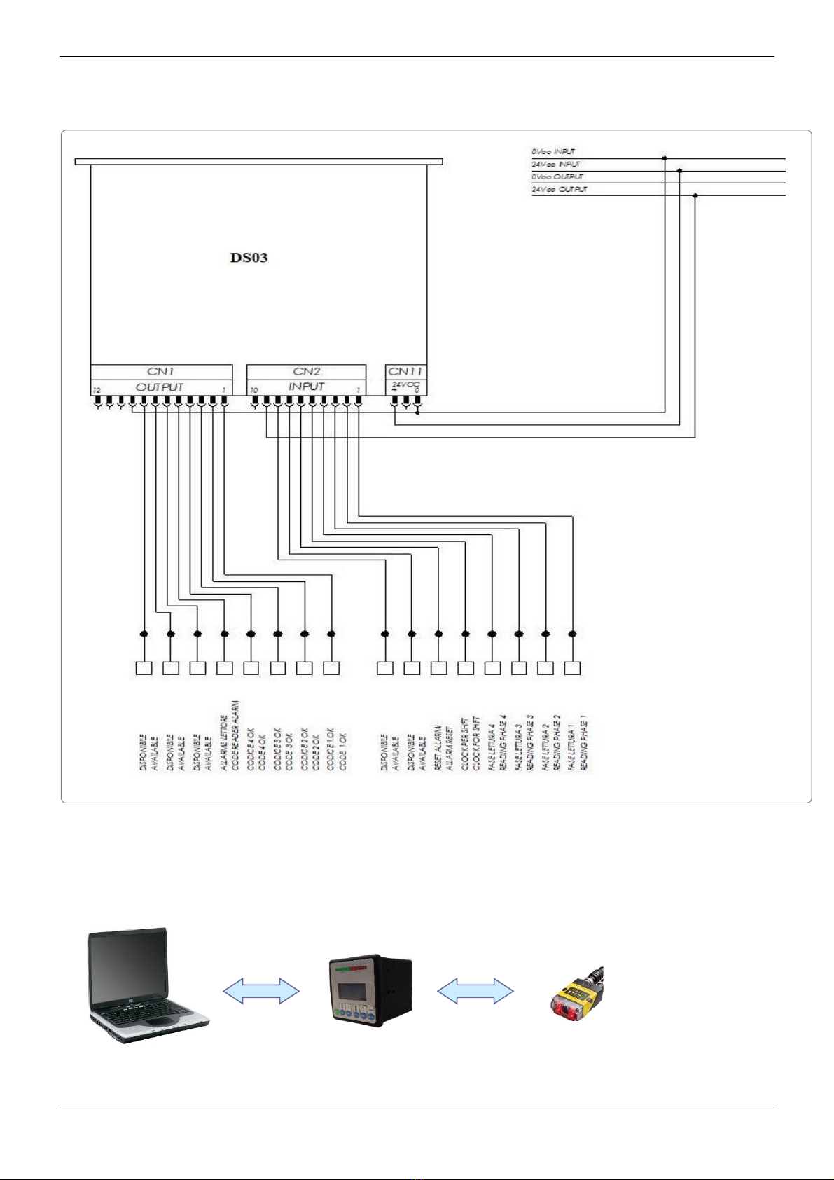
1.3. Code reader wiring diagram .................................................................................................................... 7
1.4. Connection TERMINAL ► DS03 ► DM260 ................................................................................................. 7
1.5. Front panel elements ................................................................................................................................. 8
1.6. Rear panel elements.................................................................................................................................. 8
1.7. Mounting and positioning the reading heads .......................................................................................... 9
2. DESCRIPTION OF THE SOFTWARE MENU ...........................................................................10
Front panel signals............................................................................................................................................. 10
Main 11
2.1. Setup 12
2.1.1 Head 1.......................................................................................................................................13
2.1.1.1.1 Percentage ....................................................................................................................................................14
2.1.1.2 Selection Code.................................................................................................................................. 15
2.1.1.3 Outputs setting................................................................................................................................... 17
2.2. Programming............................................................................................................................................ 18
2.2.1 Select Head ..............................................................................................................................19
2.2.2 Programming Code .................................................................................................................20
2.2.2.1 Keyboard............................................................................................................................................ 21
2.2.2.2 Autoset ............................................................................................................................................... 22
2.2.2.2.1 Code Acquired ..............................................................................................................................................23
2.2.2.3 Memory .............................................................................................................................................. 24
2.2.2.3.1 Memory read..................................................................................................................................................25
2.2.2.3.2 Memory write..................................................................................................................................................27
2.2.2.3.3 Memory delete............................................................................................................................................... 29
2.2.3 Current Format..........................................................................................................................31
2.2.4 Configuration ............................................................................................................................32
2.2.5 Shift Register ..............................................................................................................................32
2.2.5.1 Shift Register 1 .................................................................................................................................... 33
2.2.6 Consecutive..............................................................................................................................33
2.2.6.1 Errors 1= 0............................................................................................................................................ 34
2.3. Production ................................................................................................................................................ 35
2.3.1 Single head ...............................................................................................................................35
2.3.2 Multiple heads ..........................................................................................................................36
2.3.3 Reset counters .........................................................................................................................37
2.4. Language ................................................................................................................................................. 38
2.5. Programming examples .......................................................................................................................... 39
2.5.1 Head no.1 setup .......................................................................................................................39
2.5.2 Enabling reading head no.1....................................................................................................40
2.5.3 Code setting .............................................................................................................................41
2.5.4 Start of the production cycle ..................................................................................................42
2.5.5 Mounting ...................................................................................................................................43

USER MANUAL DS03 REV.1.0
This document is a property of LOGOMAT s.r.l.
No part of this document may be reproduced without the prior explicit permission of LOGOMAT s.r.l. Page. 4of 45
1. Introduction
In addition to being a practical guide for using the DS03 code reader, this manual also pinpoints the essential
aspects of the equipment.
DS03 is a compact code reader able to verify the read code. An independent CPU for each reading channel makes
for extremely fast, reliable code reading.
The reading heads are connected to the equipment by RJ45 connectors. Connection to the machine is via 10- and
12-pole industrial connectors. The equipment provides the voltage values required for operation of the reading
heads.

USER MANUAL DS03 REV.1.0
This document is a property of LOGOMAT s.r.l.
No part of this document may be reproduced without the prior explicit permission of LOGOMAT s.r.l. Page. 5of 45
1. GENERAL DESCRIPTION OF HARDWARE
1.1. Components
ITE M
Descripti o n
In combination with the terminal “DS03”
24401042D-01
CODE READER DM 260 (PROGRAMMED XDS03) CD.DMR-260Q-MAX
With relative cables (VARIOUS OPTIONS)
CVDMR260-DS03-03
POWER AND I/OCABLE XDM260 COGNEX IN COMBINATION DS03 L=3MT
CVDMR260-DS03-05
POWER AND I/OCABLE XDM260 COGNEX IN COMBINATION DS03 L=5MT
CVDMR260-DS03-10
POWER AND I/OCABLE XDM260 COGNEX IN COMBINATION DS03 L=10MT
CVDMR260-DS03-15
POWER AND I/OCABLE XDM260 COGNEX IN COMBINATION DS03 L=15MT
In combination with the "VIRTUAL DS" Software
24401042D-V01
CODE READER DM 260 (PROGRAMMED XVIRTUAL DS) CD.DMR-260Q-MAX
With relative cables (VARIOUS OPTIONS)
CCBL-05-01
POWER CABLE AND I/OSIGNALS 5MT MOD.CCBL-05 01
CCB-84901-2001-05
ETHERNET CABLE X-CODED 5MT MOD.CCB-84901-2001-05
CCB-PWRIO-15
POWER CABLE AND I/OSIGNALS CONN.M12 12P 15MT MOD.CCB-PWRIO-15
CCB-84901-2001-10
ETHERNET CABLE X-CODED 10MT MOD.CCB-84901-2001-10
CCB-PWRIO-15
POWER CABLE AND I/OSIGNALS CONN.M12 12P 15MT MOD.CCB-PWRIO-15
CCB-84901-2001-15
ETHERNET CABLE X-CODED 10MT MOD.CCB-84901-2001-15

USER MANUAL DS03 REV.1.0
This document is a property of LOGOMAT s.r.l.
No part of this document may be reproduced without the prior explicit permission of LOGOMAT s.r.l. Page. 6of 45
1.2. Central unit technical features DS03
The reading heads are connected to the equipment by RJ45 connectors.
Connection to the machine is via 10- and 12-pole industrial connectors
Specifications:
Mechanical
Dimension
96x96x100mm
Housing
Shielded
Electrical
Power supply
24Vdc
With metallic isolation
Absorption
10Watt
Reading head power unit
12Vdc/5Vdc
Inputs
N° 4 24VDC
With optoinsulation
Outputs
N° 4 24VDC
With optoinsulation
I/O display
By means of diodes on the front panel
InterfLOGOMAT with Host
RS232 C
Optical
Reading distance
Laser
Static or moving code reading
Da 45 a 70mm
Code length
Max. 50mm
Number of bars
Max. 12
Miscellaneous
Display
16 digits x 4 lines alphanumeric display
Check speed
Max. 100m/min
Programming
Self-learning
Code entering through keyboard
Code entering from memory
Codes that can be
checked
DM260
Pharma Code
EAN13 –EANB - EAN128
ITF 2/5 Check - ITF 2/5
UPCA - UPCE
Code39 Check - Code39 –Code128
UPCE

USER MANUAL DS03 REV.1.0
This document is a property of LOGOMAT s.r.l.
No part of this document may be reproduced without the prior explicit permission of LOGOMAT s.r.l. Page. 7of 45
1.3. Code reader wiring diagram
1.4. Connection TERMINAL ► DS03 ► DM260

USER MANUAL DS03 REV.1.0
This document is a property of LOGOMAT s.r.l.
No part of this document may be reproduced without the prior explicit permission of LOGOMAT s.r.l. Page. 8of 45
1.5. Front panel elements
Return to previous menu.
To select menu items individually.
To confirm and put the modifications into operation.
Multi-function key.
Multi-function key.
To confirm all selections made.
1.6. Rear panel elements
CN1 12-pole connector for machine interfacing (output)
CN2 10-pole connector for machine interfacing (input)
PROG. 10-pole connector for programming code reader
CN4 RJ45 connector for connection of reading head 1
DS2200)
CN4A RJ45 connector for connection of reading head 3
(DS2200)
CN5 RJ45 connector for connection of reading head 2
(DS2200)
CN5A RJ45 connector for connection of reading head 4
(DS2200)
RS232 9-pole connector (this port makes it possible to
connect the DS03 to the DSMC)
CN11 24Vdc power supply for code reader
DS03

USER MANUAL DS03 REV.1.0
This document is a property of LOGOMAT s.r.l.
No part of this document may be reproduced without the prior explicit permission of LOGOMAT s.r.l. Page. 9of 45
1.7. Mounting and positioning the reading heads
PlLOGOMAT the reading head at a distance of about 70mm from the code reading position. If the code is too
glossy, the reading head can be inclined by 15°.
For further information, consult the enclosed Datalogic manual.
MAIN
Select <Percentage>
ENTER
BAR OPTIMIZATION
SETUP
Select the head to set
Change the head height in order to get
the highest percentage.
ESC

USER MANUAL DS03 REV.1.0
This document is a property of LOGOMAT s.r.l.
No part of this document may be reproduced without the prior explicit permission of LOGOMAT s.r.l. Page. 10 of 45
2. DESCRIPTION OF THE SOFTWARE MENU
The program supplied with the equipment enables the following operations:
•display and monitoring of 4 codes at a time
•separate enabling and disabling of the code reading
Upon start-up, the following operations are automatically carried out:
•display of the installed software version
•loading from EEPROM of the code values used during latest production
•display of the production menu
Front panel signals
Input LEDs
1Head 1 reading phase
2Head 2 reading phase
3Head 3 reading phase
4Head 4 reading phase
5Clock shift register
6Reset for consecutive errors
7Available
8Available
Output LEDs
1Head 1 reading OK signal
2Head 2 reading OK signal
3Head 3 reading OK signal
4Head 4 reading OK signal
Report of the head that caused consecutive errors
5
6
7
8
Allarm
Off
Off
Off
On
Head 1
Off
On
Off
On
Head 2
Off
Off
On
On
Head 3
Off
On
On
On
Head 4
MAIN
Setup
Programming
Production

USER MANUAL DS03 REV.1.0
This document is a property of LOGOMAT s.r.l.
No part of this document may be reproduced without the prior explicit permission of LOGOMAT s.r.l. Page. 11 of 45
Main
To select one of the four menus shown.
To confirm the selection made and to enable the relevant menu.
Setup, for optimising location of reading heads.
Programming, displays the programming menu, thus enabling and programming the reading heads.
Production, monitors effected production, including display of read codes. The exit from this menu is
password-protected.
Language, for selecting the on-display language.
MAIN
Setup
Programming
Production
MAIN
Programming
Production
Language
PASSWORD: ESC + ESC + ESC + SCROLL + SHIFT + WRITE

USER MANUAL DS03 REV.1.0
This document is a property of LOGOMAT s.r.l.
No part of this document may be reproduced without the prior explicit permission of LOGOMAT s.r.l. Page. 12 of 45
2.1. Setup
To access this page, select command <Setup> from the MAIN menu.
With this menu you can optimized the location of the reading heads.
To select one of the reading heads.
To confirm the selection made and to enable the SETUP menu.
Return to previous menu.
By selecting one of the reading heads, you can optimise the mechanical location of the head on the machine.
SETUP
Head 1
Head 2
<Tab> <Enter>
SETUP
Head 3
Head 4
<Tab> <Enter>

USER MANUAL DS03 REV.1.0
This document is a property of LOGOMAT s.r.l.
No part of this document may be reproduced without the prior explicit permission of LOGOMAT s.r.l. Page. 13 of 45
2.1.1 Head 1
This page is accessed by selecting the <Test 1> command from the SET UP menu.
To select one of the items shown.
To confirm the selection made and to enable the relevant menu.
Return to previous menu.
SETUP 1
Download
Bar optimization
<Tab> <Enter>
SETUP 1
Bar optimization
Selection Code
<Tab> <Enter>

USER MANUAL DS03 REV.1.0
This document is a property of LOGOMAT s.r.l.
No part of this document may be reproduced without the prior explicit permission of LOGOMAT s.r.l. Page. 14 of 45
2.1.1.1.1 Percentage
To access this page, select command <Percentage> from the BAR OPT. 1 menu.
This menu displays reading precision of the code as a percentage. The higher it is, the better the precision. You
should adjust the distance of the reading heads according to precision.
Return to previous menu.
Percentage of
Correct code
▌▌▌▌▌▌
50%

USER MANUAL DS03 REV.1.0
This document is a property of LOGOMAT s.r.l.
No part of this document may be reproduced without the prior explicit permission of LOGOMAT s.r.l. Page. 15 of 45
2.1.1.2 Selection Code
To access this page, select command <Selection Code> from the SETUP1 menu.
This menu is used to set the code type which has to be recognized by the reading head.
SELECTION CODE
Head 1
Interleaved 2/5
<Tab> <Write>
SELECTION CODE
Head 1
UPCA
<Tab> <Write>
SELECTION CODE
Head 1
Pharmacode
<Tab> <Write>
SELECTION CODE
Head 1
EAN13
<Tab> <Write>
SELECTION CODE
Head 1
Code39 Check
<Tab> <Write>
SELECTION CODE
Head 1
Code39
<Tab> <Write>

USER MANUAL DS03 REV.1.0
This document is a property of LOGOMAT s.r.l.
No part of this document may be reproduced without the prior explicit permission of LOGOMAT s.r.l. Page. 16 of 45
To display the code type to be recognized.
To confirm the set code, returning to the previous menu.
Return to previous menu.
SELECTION CODE
Head 1
UPCE
<Tab> <Write>

USER MANUAL DS03 REV.1.0
This document is a property of LOGOMAT s.r.l.
No part of this document may be reproduced without the prior explicit permission of LOGOMAT s.r.l. Page. 17 of 45
2.1.1.3 Outputs setting
To access this page, select command <Outputs setting > from the SETUP 1 menu.
This menu is used to set the time of the head reading OK signal.
If the reading time is set to 0 msec, the head reading OK signal lasts till the reading phase of the next head.
The OK signal time can be set from 0 to 524 mSec.
To set the OK signal time of the head reading.
To confirm the selection made.
Return to previous menu.
OUTPUTS SETTING 1
00 mSec
Scroll=+ Shift=-
Write = confirm

USER MANUAL DS03 REV.1.0
This document is a property of LOGOMAT s.r.l.
No part of this document may be reproduced without the prior explicit permission of LOGOMAT s.r.l. Page. 18 of 45
2.2. Programming
To access this page, select command <Programming> from the MAIN menu.
This menu is used for enabling and programming the reading heads.
To select one of the items shown.
To confirm the selection made and to enable the relevant menu.
Return to previous menu.
PROGRAMMING
Select Head
Programming Code
<Tab> <Enter>
PROGRAMMING
Current Format
Configuration
<Tab> <Enter>
PROGRAMMING
Shift Register
Consecutive
<Tab> <Enter>

USER MANUAL DS03 REV.1.0
This document is a property of LOGOMAT s.r.l.
No part of this document may be reproduced without the prior explicit permission of LOGOMAT s.r.l. Page. 19 of 45
2.2.1 Select Head
To access this page, select command <Select Head> from the PROGRAMMING menu.
To select the reading head to be enabled or disabled.
To change the enabling status (ON - OFF) of the reading head.
Return to previous menu, maintaining the set status.
By pressing the Write key, the status of the reading head changes. If it was ON, it changes to OFF and vice versa.
When the head is OFF, the relevant output is on level 1 (reading head OFF). The PLC will always receive the OK code
signal.
SELECT HEAD
Head 1 On
Head 2 Off
<Tab> <Write>
SELECT HEAD
Head 3 Off
Head 4 Off
<Tab> <Write>

USER MANUAL DS03 REV.1.0
This document is a property of LOGOMAT s.r.l.
No part of this document may be reproduced without the prior explicit permission of LOGOMAT s.r.l. Page. 20 of 45
2.2.2 Programming Code
To access this page, select commad <Programming Code> from the PROGRAMMING menu.
To select one of the items shown.
To confirm the selection made and to enable the relevant menu.
Return to previous menu.
PROGRAM
Keyboard
Autoset
Memory
Table of contents
Popular Industrial Equipment manuals by other brands

Phoenix Contact
Phoenix Contact FL MGUARD 1000 Series Installation and startup guide

Vega
Vega VEGASOURCE 83 operating instructions

Siemens
Siemens SIRIUS 3RU1.1 Reference manual

ABB
ABB ACS560 Hardware manual

ITW
ITW SIMCO ION IQ Power Installation and operating instructions

Des Champs Technologies
Des Champs Technologies HVAC Air-Trap P Series Installation, operation and maintenance manual