manuals.online logo
Brands
  1. Home
  2. •
  3. Brands
  4. •
  5. SMC Networks
  6. •
  7. Industrial Equipment
  8. •
  9. SMC Networks EX260-VIL1 User manual

SMC Networks EX260-VIL1 User manual

EX260-TF222-017EN
Page 1 of 2
Instruction Manual
Fieldbus device - SI unit for Vacuum Manifold
EX260-VIL1
The intended use of this product is to control a pneumatic vacuum
manifold and I/O while connected to the IO-Link protocol.
1 Safety Instructions
These safety instructions are intended to prevent hazardous situations
and/or equipment damage. These instructions indicate the level of
potential hazard with the labels of “Caution,” “Warning” or “Danger.”
They are all important notes for safety and must be followed in addition
to International Standards (ISO/IEC)*1), and other safety regulations.
*1) ISO 4414: Pneumatic fluid power - General rules relating to systems.
ISO 4413: Hydraulic fluid power - General rules relating to systems.
IEC 60204-1: Safety of machinery - Electrical equipment of machines.
(Part 1: General requirements)
ISO 10218-1: Manipulating industrial robots -Safety. etc.
•Refer to product catalogue, Operation Manual and Handling
Precautions for SMC Products for additional information.
•Keep this manual in a safe place for future reference.
Caution
Caution indicates a hazard with a low level of risk which, if
not avoided, could result in minor or moderate injury.
Warning
Warning indicates a hazard with a medium level of risk
which, if not avoided, could result in death or serious injury.
Danger
Danger indicates a hazard with a high level of risk which, if
not avoided, will result in death or serious injury.
Warning
•Always ensure compliance with relevant safety laws and
standards.
•All work must be carried out in a safe manner by a qualified person in
compliance with applicable national regulations.
Caution
•Provide grounding to assure the safety and noise resistance of
the Fieldbus system.
Individual grounding should be provided close to the product using a
short cable.
•When conformity to UL is required the SI unit must be used with
a UL1310 Class 2 power supply.
2 Specifications
2.1 General specifications
Item
Specifications
Ambient operating
temperature
0 to +50 oC
Ambient humidity
35 to 85%RH (no condensation)
Ambient storage
temperature
-
20 to +60 oC
Withstand voltage
500 VAC applied for 1 minute
Insulation
resistance
10 MΩor more at 500 VDC,
Operating
atmosphere
No corrosive gas
Enclosure
IP67
Enclosure material
PBT
Dimensions
25.5 x 102.4 x 76.5 mm
Weight
150 g or less
2.2 Electrical specifications
Item
Specifications
Power supply
for Logic /
Inputs
Operating
voltage range
24 VDC ±10%
Under voltage
detection
16.8 VDC approx.
Power supply
for outputs
Operating
voltage range
24 VDC +10% / -5%
Internal current consumption
100 mA or less
Reversed polarity protection
Yes (Power supplies for logic /
input and outputs)
Isolation
Yes (Power supplies for logic /
input and outputs)
Maximum number of ejectors
16
Maximum number of sensors
16
2.3 IO-Link Communication specifications
Item
Specifications
Protocol
IO-Link version 1.1
IO-Link type
Device
IO-Link Port Class
Class B
Data transmission rate
38.4 kbps (COM2)
Firmware update function
Yes
Vendor ID
Ox0083 (131)
IODD File
4 station
manifold
SMC-EX260-VIL1_4-yyyymmdd-IODD1.1
8 station
manifold
SMC-EX260-VIL1_8-yyyymmdd-IODD1.1
12 station
manifold
SMC-EX260-VIL1_12-yyyymmdd-IODD1.1
16 station
manifold
SMC-EX260-VIL1_16-yyyymmdd-IODD1.1
Process
Data size
4 station
manifold
4 bytes Input / 2 bytes Output
8 station
manifold
5 bytes Input / 3 bytes Output
12 station
manifold
6 bytes Input / 4 bytes Output
16 station
manifold
7 bytes Input / 5 bytes Output
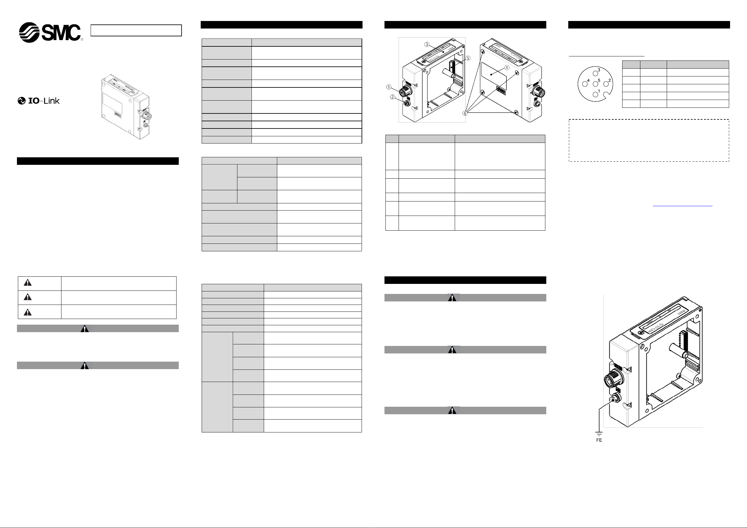
3 Name and Function of Parts
EX260-VIL1
No.
Element
Description
1
IO-Link
communication/
power supply
connector
Connector for IO-Link communication
and supplying power to the SI Unit,
pressure sensors and valves.
(M12 5-pin plug A-coded).
2
FE terminal
Functional Earth (M3 screw).
3 LED Display
LED display to indicate the status of
the SI unit.
4
Product label
Label to provide SI unit information.
5 Connector
Connector for communication with
vacuum manifold.
6 Mounting holes
Mounting hole for connection to
vacuum manifold.
4 Installation
4.1 Installation Warning
•Do not install the product unless the safety instructions have been read
and understood.
•For further details on mounting and installation tothe vacuum manifold,
refer to the vacuum manifold operation manual.
•The SI unit must be connected to a vacuum manifold before it is
powered ON.
Caution
•Be sure to turn OFF the power.
•Check there is no foreign matter inside the SI unit.
•Check there is no damage and no foreign matter on the gasket.
•If the SI unit is not assembled correctly, the internal PCBs may be
damaged or liquid and/or dust may enter into the unit.
•Tighten the screws with the specified tightening torque.
4.2 Environment Warning
•Do not use in an environment where corrosive gases, chemicals, salt
water or steam are present.
•Do not use in an explosive atmosphere.
•Do not expose to direct sunlight. Use a suitable protective cover.
•Do not install in a location subject to vibration or impact in excess of
the product’s specifications.
•Do not mount in a location exposed to radiant heat that would result in
temperatures in excess of the product’s specifications.
5 Wiring
5.1 Communication / Power Connector
•IO-Link communication and power connector layout (Port Class B).
BUS IN : M12 5-pin plug, A-coded
No.
Signal
Description
1
L+
+24 V for Logic / Inputs
2
P24
+24 V for Outputs
3
L-
0 V for Logic / Inputs
4
C/Q
IO-Link communication
5
N24
0 V for Outputs
•The power supply for logic/input and the power supply for output are
isolated.
•Select the appropriate cables to mate with the connectors on the SI
unit. Cable accessory details (SMC part number EX9-AC∗∗∗-S∗∗∗,
EX500-AP0∗0-∗and PCA-140180∗) can be found in the operation
manual on the SMC website (URL: https://www.smcworld.com).
5.2 Ground Connection
•Connect the FE ground terminal to ground.
The SI Unit must be connected to FE (Functional Earth) to divert
electromagnetic interference.
For maximum protection, the FE cable should be as thick and short as
reasonably possible.
The FE terminal and the metal parts of the fieldbus interface / power
supply connector are internally connected.
•Resistance to ground should be 100 ohms or less.
•FE terminal screw tightening torque: 0.3 N•m.
The M12 connector cable for fieldbus connections has two types,
standard M12 and
SPEEDCON compatible. If both plug and socket
have SPEEDCON connectors, the cable can be inserted and
connected by turning it 1/2 rotation.
A standard M12
connector can be connected to a SPEEDCON
connector.
ORIGINAL INSTRUCTIONS
EX260-TF222-017EN
Page 2 of 2
6 Settings
6.1 Configuration
•IODD file
An IODD (IO Device Description) file is a profile held by an IO-Link device,
which contains device specific information such as process data,
parameter and default values, vendor name and product name etc.
The content of the IODD file description is defined as the IO-Link
specification.
The IODD file is supplied with a set of image files e.g., vendor logo,
device photo and device icon.
For all parameter settings refer to the Operation manual on the SMC
website (URL: https://www.smcworld.com).
7 LED Indication
LED
Status
Description
COM
Green flashing
(900 ms ON,
100 ms OFF)
Power supply for logic / input is present
and IO-Link communication is active.
Green ON
Power supply for logic / input is present
and IO-Link communication is inactive.
OFF
Power supply for logic / input is low
(< approx. 16.8 VDC) or not present.
ST
OFF
Operating normally.
Red ON
One of the following may have occurred.
(DeviceStatus: Failure)
・Valve has a short circuit.
・Pressure sensor has a short circuit.
・Pressure sensor has failed or a
disconnection.
・No connection or a disconnection
between SI Unit and vacuum manifold.
・
There is a firmware error.
Orange ON
One of the following may have occurred.
(DeviceStatus: Maintenance-Required)
・Power supply for logic / input is low
(< approx. 16.8 VDC).
・Setting of supply valve type parameter
has a mismatch.
・Setting of Pressure / Hysteresis
parameter has failed.
・
Valve protection function is operating.
Green flashing
(1 Hz)
A firmware update is being performed via
IO-Link communications or the firmware
update has failed.
PWR(V)
Green ON
Power supply for output is present.
OFF
Power supply for output is not present.
8 How to Order
Refer to the operation manual available on the SMC website (URL:
https://www.smcworld.com) for ‘How to Order’ details.
9 Outline Dimensions (mm)
Refer to the Operation manual available on the SMC website (URL:
https://www.smcworld.com) for Outline dimensions.
10 Maintenance
10.1 General Maintenance Caution
•Not following proper maintenance procedures could cause the product
to malfunction and lead to equipment damage.
•If handled improperly, compressed air can be dangerous.
•Maintenance of pneumatic systems should be performed only by
qualified personnel.
•Before performing maintenance, turn off the power supply and be sure
to cut off the supply pressure. Confirm that the air is released to
atmosphere.
•After installation and maintenance, apply operating pressure and
power to the equipment and perform appropriate functional and
leakage tests to make sure the equipment is installed correctly.
•If any electrical connections are disturbed during maintenance, ensure
they are reconnected correctly and safety checks are carried out as
required to ensure continued compliance with applicable national
regulations.
•Do not make any modification to the product.
•Do not disassemble the product, unless required by installation or
maintenance instructions.
•Stop operation if the product does not function correctly.
11 Limitations of Use
11.1 Limited warranty and Disclaimer/Compliance Requirements
Refer to Handling Precautions for SMC Products.
12 Product Disposal
This product shall not be disposed of as municipal waste. Check your
local regulations and guidelines to dispose of this product correctly, in
order to reduce the impact on human health and the environment.
13 Contacts
Refer to www.smcworld.com or www.smc.eu for your local distributor /
importer.
URL:
https://www.smcworld.com (Global) https://www.smceu.com (Europe)
SMC Corporation, 4-14-1, Sotokanda, Chiyoda-ku, Tokyo 101-0021, Japan
Specifications are subject to change without prior notice from the manufacturer.
© 2022SMC Corporation All Rights Reserved.
Template DKP50047-F-085M
COM ST PWR(V)

Other manuals for EX260-VIL1

1

Other SMC Networks Industrial Equipment manuals

SMC Networks PSE550 User manual

SMC Networks

SMC Networks PSE550 User manual

SMC Networks ZXP7 Series User manual

SMC Networks

SMC Networks ZXP7 Series User manual

SMC Networks EX510 Series User manual

SMC Networks

SMC Networks EX510 Series User manual

SMC Networks CYP Series Instruction manual

SMC Networks

SMC Networks CYP Series Instruction manual

SMC Networks CNS Series User manual

SMC Networks

SMC Networks CNS Series User manual

SMC Networks CKZT Series User manual

SMC Networks

SMC Networks CKZT Series User manual

SMC Networks EX600-SEN5 16 Series User manual

SMC Networks

SMC Networks EX600-SEN5 16 Series User manual

SMC Networks CY3B Series User manual

SMC Networks

SMC Networks CY3B Series User manual

SMC Networks EXW1-BECAC User manual

SMC Networks

SMC Networks EXW1-BECAC User manual

SMC Networks CJP2 Series User manual

SMC Networks

SMC Networks CJP2 Series User manual

SMC Networks EX180-SAW1-X237 User manual

SMC Networks

SMC Networks EX180-SAW1-X237 User manual

SMC Networks SFDA Series User manual

SMC Networks

SMC Networks SFDA Series User manual

SMC Networks JMHZ2-16D-X7400B-CRX User manual

SMC Networks

SMC Networks JMHZ2-16D-X7400B-CRX User manual

SMC Networks VQ2000 Series User manual

SMC Networks

SMC Networks VQ2000 Series User manual

SMC Networks EX260-SCA1-X176 Manual

SMC Networks

SMC Networks EX260-SCA1-X176 Manual

SMC Networks KFG2H-C Series User manual

SMC Networks

SMC Networks KFG2H-C Series User manual

SMC Networks KFG2H-E Series User manual

SMC Networks

SMC Networks KFG2H-E Series User manual

SMC Networks AS Series User manual

SMC Networks

SMC Networks AS Series User manual

SMC Networks SY3000 SERIES User manual

SMC Networks

SMC Networks SY3000 SERIES User manual

SMC Networks CS1 N125 Series User manual

SMC Networks

SMC Networks CS1 N125 Series User manual

SMC Networks ZHP Series User manual

SMC Networks

SMC Networks ZHP Series User manual

SMC Networks MGQ Series User manual

SMC Networks

SMC Networks MGQ Series User manual

SMC Networks ZL112A Series User manual

SMC Networks

SMC Networks ZL112A Series User manual

SMC Networks REA Series User manual

SMC Networks

SMC Networks REA Series User manual

Popular Industrial Equipment manuals by other brands

ABB HT608033 Operation manual

ABB

ABB HT608033 Operation manual

Dungs MB DLE 055 D01 Installation, use and maintenance instructions

Dungs

Dungs MB DLE 055 D01 Installation, use and maintenance instructions

ABB VTR184P11 Operation manual

ABB

ABB VTR184P11 Operation manual

Bosch EPS 625 Original instructions

Bosch

Bosch EPS 625 Original instructions

DOMAILLE ENGINEERING DE8800 Series user guide

DOMAILLE ENGINEERING

DOMAILLE ENGINEERING DE8800 Series user guide

VIEWEG ViscoTec preflow eco-CONTROL EC200 DUOMIX Operation and maintenance instruction

VIEWEG

VIEWEG ViscoTec preflow eco-CONTROL EC200 DUOMIX Operation and maintenance instruction

transnorm TS 2111 operating instructions

transnorm

transnorm TS 2111 operating instructions

Jäger Z33-M060.03 K2S2A manual

Jäger

Jäger Z33-M060.03 K2S2A manual

Mayr EAS-NC Installation and operational instructions

Mayr

Mayr EAS-NC Installation and operational instructions

NCR 6003-K001-V003 installation instructions

NCR

NCR 6003-K001-V003 installation instructions

Ekso Bionics EksoVest Operator's manual

Ekso Bionics

Ekso Bionics EksoVest Operator's manual

MHS Boilers XenoROL XR40 Installation, operation & maintenance manual

MHS Boilers

MHS Boilers XenoROL XR40 Installation, operation & maintenance manual

schmersal AZM 170 operating instructions

schmersal

schmersal AZM 170 operating instructions

ABB HT576419 Operation manual

ABB

ABB HT576419 Operation manual

ABB HT606961 Operation manual

ABB

ABB HT606961 Operation manual

Pneumax COMPACT Series Installation, use and maintenance instructions

Pneumax

Pneumax COMPACT Series Installation, use and maintenance instructions

Jäger S80-K450.42 S5 manual

Jäger

Jäger S80-K450.42 S5 manual

Novalynx 255-620-A user manual

Novalynx

Novalynx 255-620-A user manual

manuals.online logo
manuals.online logoBrands
  • About & Mission
  • Contact us
  • Privacy Policy
  • Terms and Conditions

Copyright 2025 Manuals.Online. All Rights Reserved.