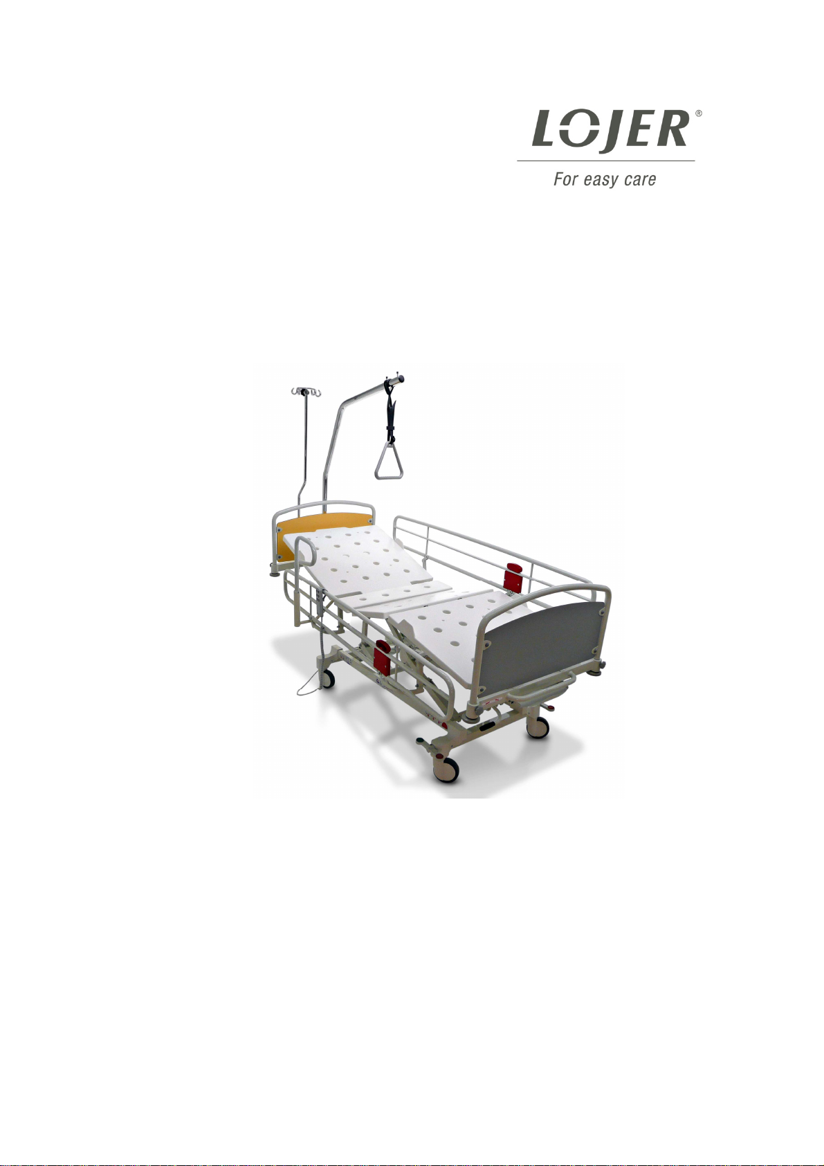
OperationinstructionsforSalliF1,F2,F3,H2andH4Hospitalbed/Version1.3
Copyright © Lojer Oy, 2010
Limited International Warranty
The warranty period is determined in the agreement documents. Unless otherwise agreed, the warranty
period for manufacturing and material defects is 2 years, except the steel structure and welds which carry
a warranty of 10 years. For wearing parts (like upholsteries, batteries, ropes/wires) the warranty is 1 year.
Warranty Conditions
The warranty is only valid if the warranty demand is presented together with the original invoice or sales
slip or (order) confirmation, and the serial number on the product has not been defaced.
LOJER’s obligations are limited to the repair or, at its discretion, replacement of the product or the
defective part. Defective parts shall be replaced with new or equivalent “as new” parts. If necessary, the
entire product shall be exchanged with an identical or functionally identical product. The value of the
warranty service is always limited to the value of the defective product. The defective parts removed from a
product as part of a warranty case shall become the property of LOJER and shall be retained for by the
End Customer for LOJER, if necessary. If these parts cannot be returned to LOJER upon request, LOJER
is entitled to charge for a corresponding amount. When genuine LOJER parts are installed in a LOJER
product under warranty, only the remaining warranty period of the repaired device applies.
Warranty repairs must be carried out by LOJER or authorised LOJER Dealers. No re-imbursement will be
made for repairs carried out by a non-LOJER representative, and any such repair work or damage to the
products caused by such repair work will not be covered by this warranty
.
The product is designed and manufactured to meet the requirements for CE-marking. This product is not
considered to be defective in materials nor workmanship if it requires adaptation in order to conform to
other local or national technical or safety standards.
This warranty covers none of the following:
a) Periodic checks, maintenance and repair or replacement of parts due to normal wear and tear (such as
upholsteries, cables, ropes or reduced capacity of accumulators);
b) Costs relating to transport, removal or installation of the product;
c) Misuse, including the failure to use this product for its normal purposes or incorrect installation;
d) Damage caused by lightning, water, fire, acts of God, natural catastrophes, war, public disturbances,
incorrect mains voltage or any other cause beyond the control of Lojer;
e) Spillage of chemicals or liquids, or use of any other hazardous or non-instructed substances, which may
affect the product;
f) Minor defects or deviations from the product specifications which are immaterial, negligible or trivial as
regards to the value or the functioning of the product
Proceeding in a Warranty Case
The following information is an explanation of what you must do in the case of a warranty claim. First,
please contact your LOJER dealer and describe the problem (possibly with photographs or videos) and
inform LOJER of the product type and serial number. LOJER’s technicians will help to diagnose defects
and malfunctions, and are often capable of eliminating the malfunction over the phone.
In the event that warranty service is required, you should return the product to the dealer from whom it was
purchased, or directly to LOJER’s factory in Finland. In this case, the customer is responsible for the
dispatch and insurance of the product, and the transport and insurance costs shall be borne by the
customer. LOJER shall assume the costs for the materials / spare parts and the labour costs as required,
as well as the standard return transportation to the sender. In case of difficulty, details of local dealers are
available online at www.lojer.com. You may also contact the service centre in Finland (e-mail:
The guarantee will become void if:
•A Lojer product is equipped or used with parts that have not been approved by Lojer for the
product in question;
•Someone other than a person authorised by Lojer has serviced/repaired or otherwise modified the
device and these measures have caused a fault in the product;
•The product is cleaned with cleaning agents other than those specified in the operating manual, or
if the product is allowed to come into direct contact with agents other than those specified in the
manual;
•Regular maintenance has not been performed.