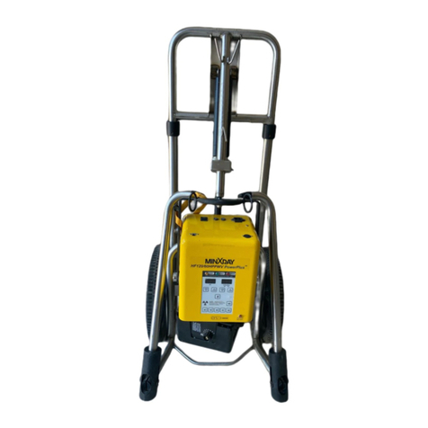
MinXray HF70DUL User manual

Appendices B & C
MinXray HF70DUL Type A ultra light
High Frequency Portable Dental X-ray unit
Installation and Operating Instructions
Version 2.0
This special purpose portable equipment is for dental radiography only.
It is not designed, nor does it meet, the standards for any other use.
MinXray, Inc.
3611 Commercial Avenue
Northbrook, Illinois 60062-1822
U.S.A.
Tel: 1-847-564-0323
Toll Free Tel: 1-800-221-2245 (U.S. and Canada)
Fax: 1-847-564-9040
www.minxray.com

TABLE OF CONTENTS
Introduction 1
Certifications 2
Recordkeeping Requirements 3
Components 5
Main Parts 6
Warning statements, figures and symbols 8
Installation Instructions
Unpacking 9
Assembly Instructions 9
Pre-Operational Required Testing 10
Installation Check list 13
Operating Instructions
BL70A Dental Cone 14
Operation 15
Safety Precautions 16
Maintenance 17
Technique Chart 20
Specifications 21
Schematic Diagram 23
X-ray Tube Data 24
Warranty 28

INTRODUCTION
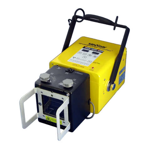
The MinXray model HF70D ultra light is a mono-block type high frequency portable dental x-ray unit.
The HF70D can be used with conventional intraoral dental film or with solid-state digital
radiographic intraoral sensors. It is supplied in a carrying case containing the x-ray
tubehead/control, detachable dental cone (beam limiting device), detachable AC power cord, and
detachable exposure cord with 2-stage exposure switch. The MinXray HF70D ultra light high
frequency dental x-ray unit is designed for use with the MinXray model X100S Tripod or equivalent
stand capable of providing secure, stable support that allows for proper positioning of the x-ray unit
for intraoral radiographic imaging.
CARELESS OR IMPROPER USE OF X-RAY EQUIPMENT CAN BE EXTREMELY HAZARDOUS.
It is imperative that this equipment be operated and serviced only by trained personnel familiar with
the safety precautions required to prevent excessive exposure to primary X-ray radiation, the
dangers of exposure to X-ray radiation, and the proper use of the equipment discussed in this
manual.
All personnel authorized to operate or service this equipment should be fully acquainted with the
established maximum permissible doses, safety recommendations, and procedures derived from
the following sources:
A. National Council on Radiation Protection Report No.33 (Medical X-Ray and Gamma
Ray Protection for Energies up to 10 MEV - Equipment Design and Use); from NRCP
Publications; P.O. Box 30175, Washington, D.C. 20014.
B. National Bureau of Standards Handbook No.76 (Medical X-Ray Protection up to Three
Million Volts); from the Superintendent of Documents, Government Printing Office,
Washington, D.C. 20401.
C. All documents relating to the Performance Standard for Diagnostic X-Ray Systems, 21
CFR Subchapter J, Part 1020; obtainable from FDA Center for Devices and Radiological
Health, Department of HHS, 2098 Gaither Road, Rockville, MD 20850.
D. State and local regulations governing radiation protection and the use of diagnostic X-
ray equipment.
E. Requirements of the user’s in-house radiation protection program.
F. Instructions and precautionary notices of this manual.
1

Although this equipment incorporates protective design features for limiting both the direct (primary)
x-ray beam and the secondary radiation produced by this beam, design factors alone cannot
prevent human carelessness, negligence, or lack of knowledge. This apparatus is sold with the
understanding that the user assumes sole responsibility for radiation safety and that MinXray, Inc.,
its agents and representatives, do not accept any responsibility for:
A. Injury or danger to patient or other personnel from x-ray exposure.
B. Overexposure due to poor operating techniques or procedures.
C. Equipment not properly serviced or maintained in accordance with this manual.
D. Equipment which has been modified or tampered with in any way.
E. Equipment that has been connected to input voltage other than the voltage specified on the
rating label affixed to the x-ray unit.
F. Equipment that is connected to input voltage not utilizing the UL listed hospital grade
detachable power supply cord set provided with the equipment.
Hand held use of this x-ray unit may be prohibited by the laws of your state. Contact the
appropriate agency responsible for radiation safety regulations in your state to confirm the
requirements of laws in your jurisdiction regarding hand held use of diagnostic x-ray equipment.
CERTIFICATIONS
M
EDICAL EQUIPMENT
W
ITH RESPECT TO ELECT
R
IC SHOCK,
LYFIRE AND MECHANICAL HAZARDS ON
IN ACCORDANCE WITH UL 2601-1,
CAN/CSA C22.2 NO. 601.1,IEC 60601-1-3,
IEC 60601-2-7, IEC 60601-2-28
79DN
THIS PRODUCT CONFORMS TO
ALL APPLICABLE DHHS
RADIATION STANDARDS OF 21
CFR SUBCHAPTER J AS OF THE
DATE OF MANUFACTURE
-2-
2

RECORD KEEPING REQUIREMENTS
1. Dealer and Distributor Records
a. Dealers and distributors of x-ray equipment shall obtain and preserve for a period of five years
from the date of sale, award, or lease of each such product, such information as is necessary to
permit tracing of specific products to specific purchasers.
b. Such information shall include:
1) The name and mailing address of distributor, dealer, or purchaser to whom the product was
transferred.
2) Identification and brand name of the product.
3) Model number and serial or other identification number of the product.
4) Date of sale, award or lease.
2. Records to be furnished to MinXray, Inc. by Dealers and Distributors
The information required in "1" above shall immediately be forwarded to MinXray unless:
a. The dealer or distributor elects to hold and preserve such information, and to immediately furnish
it to MinXray, Inc. when advised by MinXray or Director, Department of Health and Human
Services, that such information is required for purposes of Section 359 of the Radiation Control
for Health and Safety Act of 1968.
b. The dealer or distributor, upon making the election under "a" above of this section, promptly
Notifies MinXray and the Center for Devices and Radiological Health of such election. Such
notification shall be in writing and shall identify the dealer or distributor and the type of equipment
for which the information is being accumulated.
3. Assembler's Report
All assemblers who install certified components should file a report of such assembly. All
assembler's reports shall be on Form FD-2579, which is prescribed by and available from the
Director, FDA/Department of Health and Human Services, Division of Compliance, 1390 Piccard
Drive, Rockville, Maryland 20850. The original of Form FD-2579 shall be sent to the Director
and copies to the purchaser, State Agency responsible for radiation protection, and one kept by
the assembler for a period of least 5 years.
3

TO: ALL MANUFACTURERS AND ASSEMBLERS OF DIAGNOSTIC X-
RAY EQUIPMENT
SUBJECT : Final Testing of Diagnostic X-ray Systems and Components Following Assembly.
This letter is intended to establish HHS policy relative to final testing of a newly-assembled x-ray
system or component before release to the user.
Manufacturer Responsibility - The FDA believes that plant-based manufacturers must include in
their assembly instructions a specific requirement that the assembler perform a test(s) for the
applicable requirements of the FDA performance standard at the time of installation. A thorough
explanation of the equipment required and step-by-step instructions must be provide by the
component or system manufacturer. The instructions should include a requirement to record key
data to demonstrate at a later data that all tests were performed and that the equipment was left in
full compliance with the standard. The FDA's Department of Health and Human Services will insure
that these assembler test instructions are provided through a close review of the information
submitted by manufacturers in initial, model change and annual reports. Plant-based
manufacturers who do not include a final compliance test in their assembler instructions could be
subject to disapproval of their quality control and testing program.
Assembler Responsibility - Assemblers of diagnostic x-ray equipment must perform a test or tests
for the applicable requirements of the FDA performance standard at the time of installation if
specified in the assembly instructions provided by the component or system manufacturer.
Assemblers who do not perform and document such final compliance tests will be considered by
the FDA to have issued a false and misleading certification and will, therefore, be subject to
regulatory action by the Agency.
Should they be any questions concerning this Bureau policy please call X-ray Products Branch at
301-594-4591.
4

COMPONENTS
1. X-ray Unit (Model HF70DUL Type A) 1 set
2.Powercord 1pc.
3. Dental cone (Model BL70A) 1 pc.
4. Hand-held Exposure Switch and Cord 1 pc.
5. Instruction Manual 1 pc.
6. Carrying Case 1 pc.
OPTIONAL COMPONENTS
Backscatter Shield (Model BSS)
Tripod stand (Model X100S)
5

MAIN PARTS OF MinXray HF70D ultra light
Angle indicator
Exposure switch and cord
Connector for exposure switch
Connector for power cord
Power cord
Backscatter Shield
(Optional)
Dental cone
Main power switch
6

2
1
3
4
7
6
9
8
5
CONTROL PANEL
1. X-ray Indicator 6. kV Adjustment Button (-)
2. Ready Indicator 7. kV Adjustment Button (+)
3. Error Indicator 8. Exposure Time Adjustment Button (+)
4. kV Indicator 9. Exposure Time Adjustment Button (-)
5. Exposure Time Indicator
7

Warning statements, figures and symbols
WARNING: THIS X-RAY UNIT MAY BE
DANGEROUS TO PATIENT & OPERATOR UNLESS
SAFE EXPOSURE FACTORS & OPERATING
INSTRUCTIONS ARE OBSERVED
D
A
NGER: HIGH VOLTAGE.
NO USER SERVICEABLE
COMPONENTS INSIDE.
REFER SERVICE TO
QUALIFIED SERVICE
TECHNICIAN.
FOR CONTINUED
PROTECTION AGAINST
HAZARDOUS CONDITION,
REPLACE FUSE WITH SAME
TYPE AND RATING ONLY.
Radiation warning symbol
Main power on
Main power off
Attention, consult ACCOMPANYING DOCUMENTS
8

MinXray HF70DUL Type A ultra light
INSTALLATION INSTRUCTIONS
Unpacking
The MinXray HF70D ultra light portable x-ray unit consists of an x-ray tubehead and
control, mounting handle, dental cone, backscatter shield, exposure cord, power cord, and
carrying case.
If a stand is purchased with the HF70D, instructions for its assembly are included with the
stand.
When the equipment is received each shipping container should be carefully examined for
any evidence of mishandling during shipment. Note its condition, if abnormal, carefully
unpack all parts and examine for damage. If any damage is noted, immediately report it to
the carrier in the proper manner, by personally calling it to attention by phone where
possible, and filing a written report.
All printed matter supplied with the HF70D should be saved for reference during
installation and operation.
Assembly Instructions
1. Remove the HF70D, dental cone, backscatter shield, power cord, and exposure cord
from the carrying case.
2. If the HF70D will be attached to the top of the center post of the X100S tripod stand,
rotate the carrying handle of the HF70D around the rear of the unit so it is positioned
under the unit. Place one flat black rubber washer on the thread stud on the center post
of the tripod. Insert the threaded stud on the center post of the tripod through the hole
in the center of the carrying handle of the HF70D. Place the second flat black rubber
washer on the stud of the tripod center post and on top of the HF70D carrying handle.
Affix the HF70D to the tripod using the brass thumb nut. Adjust the length of each
telescoping tripod leg, and lock it. Adjust the height of the center post and lock it.
-3-
9

3. Carefully screw the dental cone into the cone holder on the front of the HF70D. Avoid
cross-threading the cone when attaching it to the HF70D. NEVER OPERATE THE
HF70D UNLESS THE DENTAL CONE IS ATTACHED.
4. If the optional BSS Back Scatter Shield was purchased for use with your HF70D, slide it
onto the open end of the dental cone after you attach the cone to the x-ray unit before
use. The BSS Back Scatter Shield is made from a clear lead-impregnated plastic. It
provides additional protection to the operator from radiation backscatter from the patient
during x-ray exposure.
5. Connect the AC power cord to the socket on the back of the HF70D. Note the rated
voltage of the HF70D before connecting it to a power source.
6. Connect the exposure cord to the RJ11 telephone-type socket on the back of the HF70D.
PRE-OPERATIONAL REQUIRED TESTING
The following test is the responsibility of the dealer and must be conducted without fail. Fill out the
checklist for this report, when installation of x-ray unit is complete.
1. EXPOSURE TIMER
1-1 Test method:
1. Set HF70D exposure timer to 0.02 sec.
2. Set HF70D output to 70 kV.
3. Set NERO to the following settings.
SID: 18 inches; Wheel range: 50 ~ 85 kV; Sensitivity: Low; Phase select: 1Ø;
Measurement mode: STAT; X-ray values: 70 kV, 0.02 sec.
10

4. Make exposure and read the measured value of exposure time on the NERO.
5. Measure value of exposure time at following settings with same procedure: 0.02, 0.04,
0.10, 0.20, 0.50, and 1.00 sec.
1-2 Instruments: NERO Model 6000M x-ray beam analyzer
Manufactured by Victoreen, Inc. or equivalent
1-3 Rejection limit: ±10%+1 msec.
If the timer needs adjustment: (1) remove the 4 screws on the side of the top cover of the HF70D,
and lift the top off of the body of the unit; (2) adjust the potentiometer "VR3"on the printed circuit
board M3115 on the inside of the top cover (see Fig.1) so that radiation exposure time equals the
indicated time value, taking into consideration the accuracy tolerances; (3) replace the top cover
and 4 screws.
Fig.1
2. PEAK TUBE POTENTIAL
2-1 Test method:
1. Set HF70D exposure timer to 0.2 sec., and set kV to 60 kV.
2. Set NERO to the following settings:
SID: 18 inches; Wheel range: 50 ~ 85 kV; Sensitivity Hi; Phase select: 1Ø;
Measurement mode: SGL; Time delay 0.1 sec; X-ray values: 60 kV, 0.2 sec.
3. Make exposure and read the measured AVG. kV value on the NERO.
4. Measure also value of AVG. kV at 65 kV, 70 kV with same procedure.
2-2 Instruments: NERO Model 6000M x-ray beam analyzer
Manufactured by Victoreen, Inc. or equivalent
2-3 Rejection limit: ±10%
11

If the peak tube potential needs adjustment: (1) remove the 4 screws on the side of the top cover
of the HF70D, and lift the top off of the body of the unit; (2) adjust the potentiometer "VR3" on the
printed circuit board M9142 located on top of the lower portion of the unit (see Fig. 2) so that
peak tube potential equals the indicated kV value, taking into consideration the accuracy
tolerances; (3) replace the top cover and 4 screws.
3. TUBE CURRENT
3-1 Test method:
1. Set HF70D to 60 kV, and timer to 0.2 sec.
2. Set oscilloscope to the following settings.
ch 1:Ep, ch 2:Ip, ch1 V/div: 1V, ch2 V/div: 500 mV, sec/div: 25 msec,
trigger level: ch1 1.5 V
3. Open the top cover of the HF70D by removing the 4 screws and lifting the cover off of
the unit. Connect ch 1 of oscilloscope to Ep pin of PC board M9142 and connect ch 2 of
oscilloscope to Ip pin of PC board M9142. Connect GND line of probe to GND pin of
PC board M9142.
4. Make exposure, and measure Hi value of ch 2. 1.0 V is equal to 10 mA.
5. Measure Hi value of ch 2 at 70 kV and 0.2 sec. with same procedure.
3-2 Instruments: Digital Storage & Analog Oscilloscope 2212
Manufactured by Tektoronix Holland, N.V. or equivalent
3-3 Rejection limit: ±20%
If the tube current needs adjustment: (1) adjust the potentiometer "VR4" on the printed circuit
board M9142 (see Fig. 2) so that tube current equals 10 mA, taking into consideration the
accuracy tolerances; (2) replace the top cover and 4 screws.
Fig.2
- 6 -
12

INSTALLATION CHECK LIST
INSTALLATION CHECK
LIST HF70DUL Type A
SERIAL NO.
Fill out this checklist
when installation is
complete. DATE
MANUFACTURED
EQUIPMENT LOCATION
TEST
DESCRIPTION
ACCEPTANCE
LIMITS RESULTS CHECK
Line Voltage 110~130 V
……….V
GO NO GO
Line Voltage
Regulation
≤4.8% ………..%
GO NO GO
Peak Tube Potential
60 kV±10%
65 kV±10%
70 kV±10%
………kV
………kV
………kV
GO NO GO
Tube Current 10mA±20% ………mA
GO NO GO
Exposure Time 0.02 sec ±10%+1 msec.
0.04 sec ±10%+1 msec.
0.1 sec ±10%+1 msec.
0.2 sec ±10%+1 msec.
0.5 sec ±10%+1 msec.
1.0 sec ±10%+1 msec.
………sec
………sec
………sec
………sec
………sec
………sec
GO NO GO
All Mechanical
Movement
Smooth Movement
GO NO GO
All Operation See operation Manual
GO NO GO
Manufacturer Model Accuracy Last calibrated
Instruments
Used
Dealer Name Dealer Phone Number
Dealer Address
Assembler signature Date
Comments
- 7 -
13

INSTRUCTION MANUAL FOR BL70A DENTAL CONE
CAUTION: This special purpose beam limiting device is developed for use with an intraoral dental
x-ray unit only. It is not designed, nor does it meet, the Standards for any other use.
ASSEMBLY: Carefully screw clockwise the BL70A dental cone into the cone holder on the front of
the x-ray tubehead. Avoid cross-threading the cone when attaching it to the
tubehead to prevent leakage radiation and distortion of the x-ray field.
NEVER OPERATE THE X-RAY UNIT UNLESS THE DENTAL CONE IS ATTACHED.
CHECK: Confirm that there are no cracks or chips on the dental cone. If there are any cracks or
chips on the dental cone, replace it with a new, intact cone. NEVER OPERATE THE X-
RAY UNIT WITH A DAMAGED DENTAL CONE.
MinXray, Inc.
3611 Commercial Avenue
Northbrook, Illinois 60062-1822
U.S.A.
Tel: 1-847-564-0323
Toll Free Tel: 1-800-221-2245 (U.S. and Canada)
Fax: 1-847-564-9040
www.minxray.com
14

HF70DUL Type A OPERATION INSTRUCTIONS
Operation
1. Connect the AC power cord to a grounded electrical outlet. Check the label on the
HF70D for the correct AC input voltage and amperage required.
2. Turn on the main power switch on the HF70D. The kV and sec LED displays will light
and remain on. The HF70D has internal circuitry to automatically compensate for
variations in the input voltage to assure consistent kV and mA output.
3. Select the kV output by pressing the arrows below the kV display to choose 60, 65, or
70 kV. 10 mA output is fixed at all kV settings.
4. Select the exposure time by pressing the arrows below the sec display to choose
between 0.02 and 1.98 second exposures.
5. Position the x-ray unit for the intraoral image you will be taking.
6. The exposure switch has a 2-stage button.
The first stage pre-heats the filament of the x-ray tube. When this stage alone is
depressed and held, “ READY ” indicator will light after 1.5 seconds, indicating
the filament was heated and the unit is ready to generate x-rays.
The second stage initiates the x-ray exposure for the time set in the sec display.
When the second stage is fully depressed, x-ray will be emitted, the X-RAY
indicator will light, and an audible signal will be heard. PRESS AND HOLD THE
FIRST AND SECOND STAGE BUTTONS TOGETHER UNTIL THE
EXPOSURE HAS TERMINATED. This is a “dead man” exposure switch--x-ray
exposure will terminate immediately as a safety feature when the buttons are
released.
15

-8-
7. After each exposure, release the exposure buttons. The HF70D is now ready for the
next exposure.
8. When you are finished using the HF70D, turn off the main power switch, disconnect the AC
power cord and exposure cord, unscrew the dental cone, and repack these components
with the HF70D into the carrying case.
Safety Precautions
1. During exposure the operator must stand as far as possible from the patient being x-
rayed, and should wear a lead apron or stand behind a lead shield.
2. The operator must not stand in the primary x-ray beam.
3. The operator should wear a monitoring dosimeter while operating this unit. It should be
worn where it is not covered by a lead apron.
4. X-ray exposure should be kept as short as possible.
5. NEVER OPERATE THE HF70D UNLESS THE DENTAL CONE IS ATTACHED.
6. The presence of radio frequency (RF) or electromagnetic radiation may adversely affect
the operation of this device. Please keep this equipment away from likely sources of
RF radiation.
If the operator is hand holding the HF70DUL Type A during exposure, the operator must wear
lead gloves, a lead apron, and a monitoring dosimeter. Only use model BL70A dental cone
(beam limiting device) for hand held use. The optional BSS backscatter shield should be used
to protect the operator from radiation backscatter during exposure. Check with your state's
radiation safety agency to determine if hand held operation of diagnostic x-ray equipment is
allowed in your state.
16

Preventive Maintenance
Clean the HF70D as needed with a damp sponge or cloth and mild soap.
Before each use:
1. Tubehead
Make sure the certification and identification labels are in place.
Check for any loose or missing screws.
Check for oil leaks.
Check for any physical damage.
Check the kV adjustment for proper operation.
Check the timer for proper operation.
Check all cords and cord connections.
Check the exposure buttons--the exposure must terminate if the button is released
during an exposure.
1.
2. Dental Cone (beam limiting device)
Make sure the certification label is on the cone.
Check for any physical damage.
3. Indicators
Check the X-RAY indicator for proper operation when both exposure buttons are
depressed and held.
Make sure the audible signal operates during an exposure.
If the ERROR INDICATOR is on, it means the unit has malfunctioned and x-ray cannot
be generated.
If ERROR INDICATOR is lit even after the EXPOSURE SWITCH is released, it means an
unusual situation has occurred. Turn off the MAIN POWER SWITCH, wait 3 minutes, then
start procedures over again. If the ERROR INDICATOR remains on, contact your dealer or
MinXray for service.
17

*** Have this unit checked by qualified service personnel immediately if any problems occur with the
HF70D.
Every 12 months
Calibration should be checked and adjusted if necessary at 12-month intervals by qualified service
personnel to assure that the HF70D is operating within its stated specifications. The following items
should be checked:
kV output should be ±10%.
mA output should be ±20%.
Exposure time should be ±10%+1ms.
Every 2 years
Radiation leakage should be measured by qualified service personnel. If leakage radiation at 1
meter is > 10 mR/h, contact MinXray Technical Service department for assistance. Follow these
steps to take these measurements:
Set ion chamber of the x-ray dosemeter at a distance of 1 meter from the HF70D at
each of the 5 positions below:
Top view Side view
Cover the open end of the beam limiting device (BLD) with lead. Set kV to 70 and
exposure time to 1.0 sec. Make exposure.
18
Table of contents
Other MinXray Medical Equipment manuals
Popular Medical Equipment manuals by other brands

Drive
Drive RTL12087 quick start guide

Tecno-gaz
Tecno-gaz SLIM Instruction manual for use and installation

Atmos
Atmos Variotherm plus operating instructions

Dräger
Dräger 2M85674 Instructions for use

Fehling Instruments
Fehling Instruments CERAMO CONCEPT X PUNCHES Assembly instructions

Invivo
Invivo dS HiRes Hand/Wrist 16ch 1.5T Instructions for use