Lojer Scandia SC330 Instruction Manual

Lojer Scandia SC330- operating table
Instructions of use
12.05.2014

Copyright © Lojer Oy, 2014 | 05/2014
2
Contents
1 Lojer Scandia SC330 Operating table............................................................................................................ 4
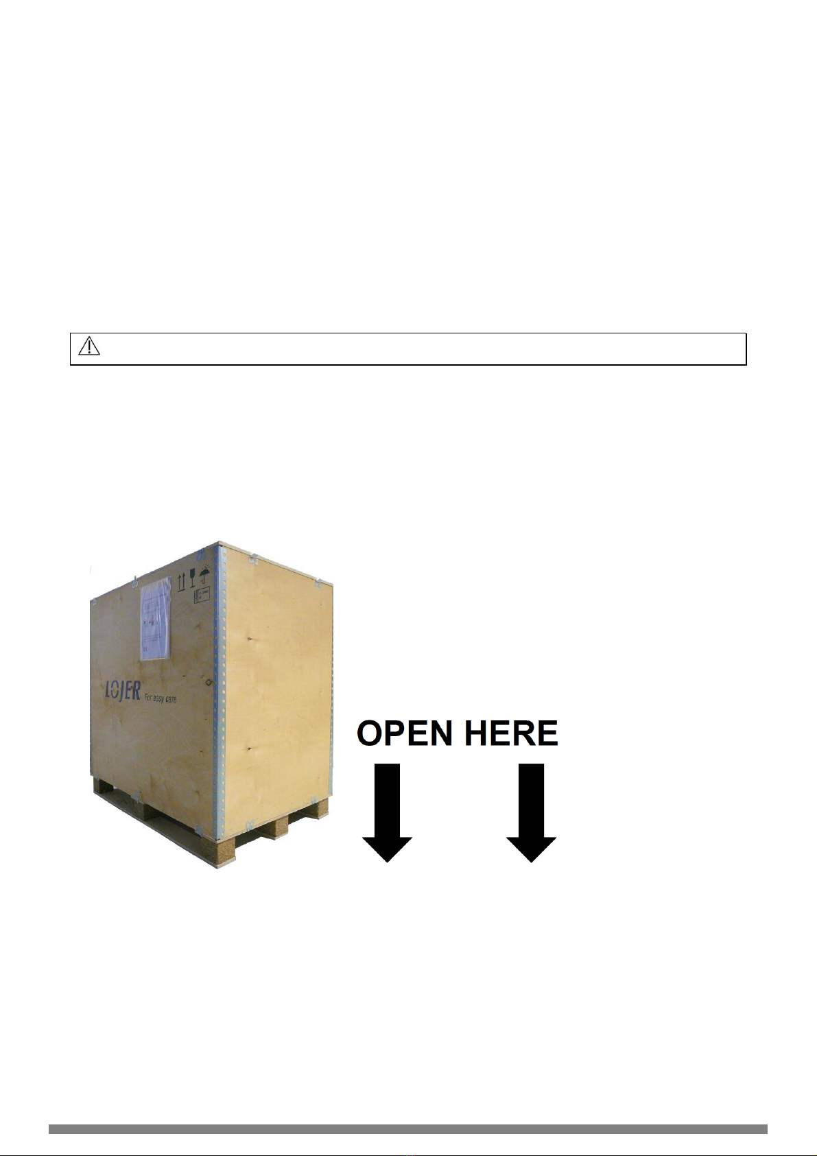
1.1 Content of the package........................................................................................................................... 4
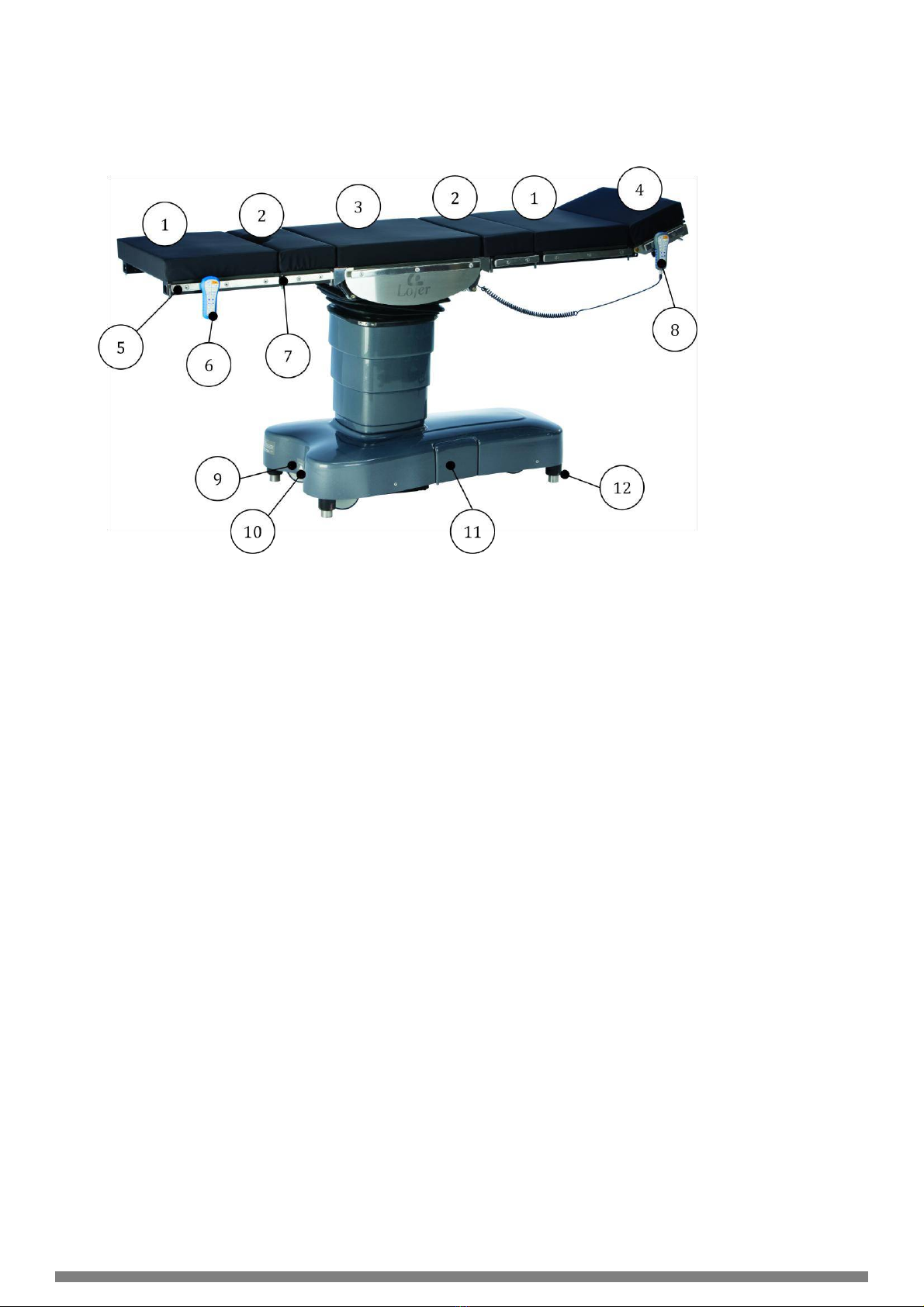
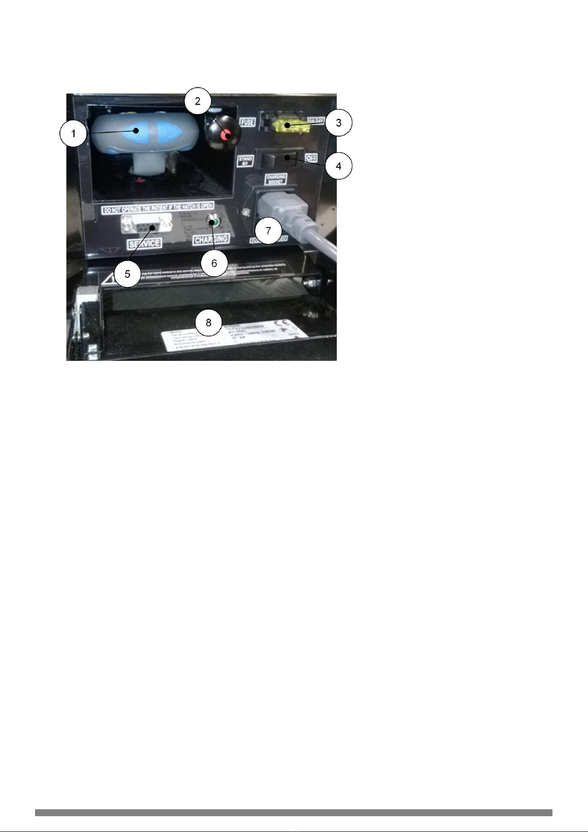
1.2 Description of parts ................................................................................................................................. 5
1.3 Controls................................................................................................................................................... 7
1.3.1 Hand control..................................................................................................................................... 7
1.3.2 Wireless (blue) Bluetooth hand control (Option).............................................................................. 8
1.3.3 Foot control (Accessory).................................................................................................................. 8
1.4 Options and accessories......................................................................................................................... 8
1.5 Markings and signs ................................................................................................................................. 9
2 Introduction................................................................................................................................................... 10
2.1 Inspection upon delivery........................................................................................................................ 10
2.2 Before use............................................................................................................................................. 10
3 Using the device ........................................................................................................................................... 12
3.1 Indicator LEDs (hand control) and audible signals ............................................................................... 13
3.2 ON/StandBy (Power ON/StandBy)........................................................................................................ 14
3.3 Working position (Floor locks down)/Transport position (floor locks up) .............................................. 14
3.4 Patient orientation ................................................................................................................................. 15
3.5 Adjustments........................................................................................................................................... 15
3.5.1 Height adjustment.......................................................................................................................... 15
3.5.2 Back section adjustment................................................................................................................ 15
3.5.3 Leg section adjustment.................................................................................................................. 15
3.5.4 Lateral tilt........................................................................................................................................ 15
3.5.5 Trendelenburg/Antitrendelenburg.................................................................................................. 15
3.5.6 Zero-position.................................................................................................................................. 16
3.5.7 Slide (Option)................................................................................................................................. 16
3.5.8 Memory slot.................................................................................................................................... 16
3.5.9 Transporting the operating table.................................................................................................... 16
3.5.10 Directional or Driving wheel (Option)........................................................................................... 17
3.6 Attaching/removing the table top sections ............................................................................................ 17
3.7 Head section adjustment....................................................................................................................... 18
3.8 Charging the batteries........................................................................................................................... 19
4 Table top configurations ............................................................................................................................... 20
4.1 Standard configuration.......................................................................................................................... 20
4.2 Safe working load (SWL) 350 kg........................................................................................................... 20
4.3 Lithotomy configuration, step 1 ............................................................................................................. 21
4.4 Lithotomy configuration, step 2 ............................................................................................................. 21
4.5 Cardiovascular configuration................................................................................................................. 21
4.6 TUR configuration ................................................................................................................................. 22
4.7 Prohibited configurations....................................................................................................................... 22
5 Movement limitations.................................................................................................................................... 23
6 Cleaning and disinfecting ............................................................................................................................. 24

Copyright © Lojer Oy, 2014 | 05/2014
3
7 Service and maintenance............................................................................................................................. 25
7.1 Monthly maintenance............................................................................................................................ 25
7.2 Annual service....................................................................................................................................... 25
7.3 Troubleshooting..................................................................................................................................... 26
7.4 Electrical safety..................................................................................................................................... 28
8 Technical information.................................................................................................................................... 29
8.1 Standards.............................................................................................................................................. 30
8.2 Recycling............................................................................................................................................... 30
9 Limited international warranty....................................................................................................................... 31
10 Contact information..................................................................................................................................... 32
Read these instructions carefully. Follow all warnings and instructions marked on the product
Lojer Group is leading producers of medical furniture and physiotherapy equipment in Nordic
Countries. We design and manufacture medical and treatment furniture to be used by health
care professionals in various operating environments. Lojer has committed to develop and
manufacture these devices in a sustainable manner in order to provide best possible care for
the patient today and in the future.

Copyright © Lojer Oy, 2014 | 05/2014
4
1 Lojer Scandia SC330 Operating table
Lojer Scandia SC330 Operating table is designed to be used in surgical procedures for humans carried out
in operating rooms by healthcare professionals.
The operating table is designed to be primarily used with batteries. The operating table has various hydraulic
adjustments which ensure diverse functions required in various operations. All functions are operated with
hand control. Operating table consists of reconfigurable table sections that can be adjusted according to
what is required in an operation.
This document gives instructions for operating and maintaining the device. Please familiarize yourself with
these instructions before using the device. Use the device only as described and for the specified
applications. Store these instructions in an appropriate way, making sure that the instructions are available to
all possible users throughout the life of the device.
To avoid injury, follow the instructions given in this document
1.1 Content of the package
The operating table is packed in a wooden transport box (Figure 1) which contains:
grey hand control (1 pcs)
hand control cable
auxiliary hand control (grey or blue (Bluetooth))
20 A fuse
RS232 cable for computer connection (service software)
USB adapter
USB- memory stick, which contains service software, operating software
Figure 1: Lojer Scandia SC330 wooden transport box

Copyright © Lojer Oy, 2014 | 05/2014
5
1.2 Description of parts
The parts of the Lojer Scandia SC330 operating tables are shown below (Figure 2).
1
40 cm section (2 pcs.)
2
25 cm section (2 pcs.)
3
Middle section
4
Head section
5
Accessory rail
6
Auxiliary hand control (wireless)
7
Locking latch
8
Hand control
9
Potential equalization conductor
10
Foot control connector
11
Main connection panel
12
Floor locks
Figure 2: Lojer Scandia SC330 operating table in standard configuration

Copyright © Lojer Oy, 2014 | 05/2014
6
Main connection panel is shown below (Figure 3).
1
Auxiliary hand control
2
Emergency release for floor locks
3
20 A fuse
4
Main switch (OFF/Stand By)
5
Computer connection (service software)
6
Charging indicator LED (green)
7
Charging cable and its connection
8
Type plate
Figure 3: Main connection panel

Copyright © Lojer Oy, 2014 | 05/2014
7
1.3 Controls
The functions of the table are operated with the hand controls or with the foot control which is available as an
option. In order to adjust the table, press the button of the function in question on the control. The movement
stops, when the button is released.
1.3.1 Hand control
The grey hand control is connected to the table with a cable. The connection point is located on the column
under the middle section (Figure 4).
As a standard the auxiliary hand control is grey. The wireless Bluetooth control (blue) is available as an
option. The auxiliary hand control is located in hatch on the main control panel (see Figure 3). It is connected
to the table with a cable.
Make sure that the auxiliary hand control cable doesn’t compress the button, when storing the
control in the hatch.
Both hand controls have the same buttons and symbols (Figure 5). Controls operate in parallel e.g. indicator
LED’s illuminate identically on both controls. However you cannot select functions simultaneously with both
hand controls i.e. you can operate the table only with one hand control at a time.
Figure 5: Hand control
Figure 4: Hand control connector on the column under the middle section

Copyright © Lojer Oy, 2014 | 05/2014
8
1.3.2 Wireless (blue) Bluetooth hand control (Option)
The battery of the Bluetooth hand control is automatically charged when the control is connected with the
cable to the table.
NOTE! The battery of the hand control is charged only when the main switch is on StandBy-position.
When the Bluetooth-control is connected to a operating table, it will be coded (paired) with the table in
question. This means that the control cannot be used with any other Scandia operating tables without
recoding. In order to code the control, connect it to the table with the cable on the main panel. Turn the main
switch to OFF-position and then back to ON-position. Wait 5-10 seconds after which the control is ready to
be used. Detach the hand control from the cable and turn it on from the ON/StandBy button (Figure 5 (1)).
The indicator LED on the Bluetooth control starts to flash (Figure 5 (3)) and the control starts to establish the
wireless connection. Usually this will take few seconds. When the connection is established, before
mentioned LED stays ON and the control can now be used wirelessly. The operating range of the Bluetooth
control is 5-10 meters in an open space. If the connection cannot be established (usually due to interference
or obstacles) approx. within 8 seconds, the control will turn off. Press ON/StandBy button in order to retry
establishing the connection.
If the Bluetooth control is not used for 30 min. in wireless mode, the control will go to power save mode.
Press the ON/StandBy button in order to reactivate the control.
1.3.3 Foot control (Accessory)
The functions of the table can be operated also with a foot control which is available as an accessory (Figure
6). The functions of the foot control are programmed according to the customer’s order with the Lojer Service
Software. 1-3 functions can be programmed. The symbols are identical with the hand control symbols. The
foot control is connected to the table on the short section of the lower frame (see Figure 2 (10)). Remove the
cover of the connector and attach the cable by pressing it. Ensure the fastening by tightening the thumb
screws.
a) b)
The programmed functions can be changed. Contact the Lojer Service for reprogramming.
1.4 Options and accessories
Lojer Scandia SC330 Operating tables are available with following options and accessories:
Wireless hand control (Bluetooth™)
Sliding table top (Slide)
Directional wheel
Driving wheel
Stainless steel casing
Accessories:
Foot control
Visco elastic or moulded mattresses
Wide range of accessories
Figure 6: a) Foot control (Note! Figure indicative, the symbols depend on the programmed functions)
b) Foot control connected to the table

Copyright © Lojer Oy, 2014 | 05/2014
9
1.5 Markings and signs
Markings and signs used in the documentation and on the table are shown below (
Table 1 and Figure 7)
Table 1: Symbols
Symbol
Desciption
CE
The device is in conformity with essential requirements of the Directive
93/42/EEC (Medical devices)
IP24
Effective against middle sized objects and splashing of water.
Type B medical device
Squeezing hazard
Read the instructions
Important/Warning
Warning
Figure 7: Safety signs on the column

Copyright © Lojer Oy, 2014 | 05/2014
10
2 Introduction
2.1 Inspection upon delivery
Before the device is taken into use, check that the packaging is intact and that it has not been damaged
during transportation. Please notify the transport company and the supplier of any transit damage within two
(2) days of receiving the delivery.
Ensure that the delivery contains all the parts detailed in the delivery note. If there is anything missing from
the delivery consignment, please contact the supplier immediately.
The device can be stored at a temperature of -5...+60 °C. The permitted humidity is 30...75 %.
Air pressure 700 hPa…1600 hPa.
2.2 Before use
The device is intended to be used in normal, dry indoor conditions. Ensure that the temperature of the room
is between +10…40 °C and the humidity is within the range of 30…75 %. After transport keep the operating
table in room temperature for 6 hours before use. If there is chance that device has been exposed to
temperatures below 0°C, allow it to adjust to the indoor temperature over night before using any of its
features.
Familiarize yourself with the instructions and carry out the following before using the device:
Make sure that all packing materials have been removed.
Make sure that the device can freely move up and down.
Attach the potential equalization cable to the connector (Figure 2 (9)).
Open the main connection panel and attach the 20 A fuse to its place (Figure 3 (3)).
Turn the power on from the main switch (ON) (Figure 3 (4)).
Attach the charging cable to its connector in the main control panel (Figure 3 (7)) and charge the
batteries.
Charge the batteries for 8-12 hours before taking the table in use (see Chapter 3.8).
Attach the hand control cable on the grey hand control (Figure 2 (8)) and on the column under the
middle section (Figure 4) (make sure that the connector is properly in place). Tighten the connector
on both ends. Attach the auxiliary hand control similarly to the cable on the main control panel
(Figure 3 (1)).
Test that all function work properly with both hand controls.
Check that the wheels spin freely and turn 360 °.
Check that all accessories work properly. Familiarize yourself with the instructions of use carefully
before installing the accessories and make sure that they do not compromise the safety.

Copyright © Lojer Oy, 2014 | 05/2014
11
Familiarize yourself with the following safety instructions before use:
Ensure adequate training before use.
For safety reasons always connect the power cord (charging cable) to grounded socket.
Do not bind the charging cable to the device. Ensure that the cable is easily detachable in an
emergency situation.
Make sure that the distance to the socket is not more than 2 meters.
Always detach the charging cable on both ends before moving the device.
If the charging cable is damaged, unplug it immediately. Do not use the device and contact
the service. Use only the original cable.
Do not modify the structure of the device or install parts other than those mentioned in this
document which are approved by the manufacturer.
Do not use the device or the accessory if it doesn’t work properly. Contact the service
Make sure that during assembly and possible adjustments all the levers are locked properly
before using the table.
Use the device according to the intended use defined by the manufacturer.
Ensure that the table is not exposed to electromagnetic radiation exceeding applicable norms.
Portable and mobile RF communications equipment can affect the operating table.
Use antistatic mattresses, cushions and textile to ensure discharge of static electric.
Always use potential equalization when using the table to avoid electrical interference.
Do not use the operating table in any other configurations than those mentioned in this
document (see Chapter 4) even though they might be mechanically possible.
Make sure that the sections are properly locked before use (see Chapter 3.6)
Keeps the hand control hanging on the end of the head section to keep it from getting
squeezed during transport or adjustment
Make sure that the patient’s limbs do not get caught in the frame of the device or the
accessories.
Make sure that the sections do not crash with lower frame, column or floor when adjusting the
height of the table. Pay extra attention to this especially when the table is in lower position.
Always turn the power off from main switch on the main control panel (switch in OFF-position)
during cleaning, service and emergency.
Always make sure that the table is on working position (floor locks down) before using the
table.
Make sure that there is enough space around, above and below the table for the movements.
Notice that the accessories increase the need for space.
Make sure that the space around the table is safe. There should be no sharp edges or other
possibly harmful objects around the table.
Do not modify the structure of the field operating table or install accessories other that those
mentioned in this document.
Make sure that the loading on the table is as even as possible in order to avoid tilting.

Copyright © Lojer Oy, 2014 | 05/2014
12
Safe working load (SWL) is the maximum allowed load including the patient, mattresses and
accessories. Overloading may result in tilting of the table.
Safe working load (SWL) 350 kg is allowed only with specified configuration (see Chapter 4.2)
Safe working load (SWL) in standard configuration is 280 kg. When Slide is out the SWL is
200 kg.
In reverse standard configuration the safe working load (SWL) is 250 kg (also with Slide out).
On wheels the safe working load (SWL) is 250 kg. The height of the table has to be under 80
cm.
Total mass of the accessories attached on the accessory rails is 40 kg.
Maximum allowed load (SWL) on one accessory rail is 25 kg. The maximum allowed load
(SWL) on the accessory rail of the heads section is 10 kg per rail. The maximum combined
load on the head section rails is 20 kg.
3 Using the device
A movement starts when a button on the hand control is pressed. The movement stops when the button is
released. When pressing two buttons at a same time, the table won’t move or the movement stops.
Expect following:
The table adjusts automatically to working/transport position when the button is pressed. The
movement stops only by pressing the ON/StandBy- button (Figure 5 (1)).
The movement will not stop if the same button is pressed from both hand control simultaneously.
The movement stops when either one of the buttons is released.
Pressing the Drive-buttons (Figure 5 (24/25)) does not affect the movements of a table in working
position.
Slide-movement stops for a while and move sequentially.
Trajectory of each movement is restricted with sensors. The movement stops when the button is released or
when the movement reaches the set end position. The movement will always stop, when the ON/StandBy-
button (Figure 5 (1)) is pressed.
Make sure that the accessories do not hit anything when adjusting or transporting the table.
The operating table will go to low current consumption mode (Stand By) when the
ON/StandBy button (Figure 5 (1)) is pressed. This might lead to battery discharge. In order to
turn the power off totally, turn the power off from the main switch (Figure 3 (4)).

Copyright © Lojer Oy, 2014 | 05/2014
13
3.1 Indicator LEDs (hand control) and audible signals
The definitions of the indicator LEDs and audible signals are presented below (Table 2). See also Chapter
7.3 Troubleshooting.
Table 2: Indicator LEDs of the hand control and audible signals (see also Figure 5)
Indicator LED or signal
Description
Definition
Green
Continuous (Figure 5 (2))
Table operational, battery charge
sufficient.
Slowly flashing (Figure 5 (2))
Battery charge decreased
Note! Observe the state of the
battery level and prepare to
charge the batteries.
Continuous (Figure 5 (9))
Chosen patient orientation.
Yellow
Continuous (Figure 5 (4))
Charge in progress, charge cable
(mains) connected
Red
Continuous (Figure 5 (5))
Battery charge critically low.
Charge the batteries immediately.
Changing green (Figure 5 (6)) and
yellow (Figure 5 (7)) LED
The table changing between
working and transport positions.
Wait until the either one of the
LEDs is continuous.
Blue
Flashing (Figure 5 (3))
The hand control is establishing
the wireless connection.
Continuous (Figure 5 (3))
Wireless connection between the
hand control and the table is
established.
Slowly changing green (Figure 5
(6 and yellow (Figure 5 (7)) LED
Either the directional wheel or the
drive wheel is activated (both
optional)
All LEDs (Figure 5 (2,4,5)) are
flashing simultaneously. During
movements sequential audible
signal.
Repeated beep.
Internal error mode (see Chapter
7.3)
Short signal
One beep.
Table is adjusting and the desired
movement has reached the end
position e.g. the leg section is at
its end position or the floor lock
mode has changed
(working/transport position).
Double signal
Two beeps.
Operation cancelled.

Copyright © Lojer Oy, 2014 | 05/2014
14
3.2 ON/StandBy (Power ON/StandBy)
Press the ON/StandBy button on the hand control (Figure 5 (1)) in order to use the table. During start-up
sequence the LEDs flash as a string and the table cannot be adjusted. The table is ready for use, when the
indicator LEDs for power (Figure 5 (2)), floor locks (Figure 5 (6/7)) and patient orientation are lit. In order to
save the batteries, the power is turned off after a period of time (programmable 1-240 min) if no functions are
used. All functions can be reactivated by pressing the ON/StandBy button. Turn the power by pressing the
ON/StandBy button until the LEDs turn off.
By turning the power off from the ON/StandBy button, all functions are shut down. Use the
button when immediate cancellation of movement is necessary.
3.3 Working position (Floor locks down)/Transport position (floor locks up)
The table adjusts automatically to working/transport position when the button is pressed. The
movement stops only by shutting down the power (pressing the ON/StandBy- button). If shut
down the power in order to stop the movement, put the power back on to make sure that the
floor locks are completely up or down.
In order to set the table in working position, press the button (Figure 5 (6)) on the hand control. The floor
locks descend. Indicator LEDs (green and yellow) start flashing in turn. Short signal can be heard and the
indicator LED for working position ( Figure 5 (6)) is lit when the floor locks are completely down and the table
is in working position.
In order to set the table on transport position, press the button approx. 1 second (Figure 5 (7)) on the hand
control. The floor locks get up. . Indicator LEDs (green and yellow) start flashing in turn. Short signal can be
heard and the indicator LED for transport position ( Figure 5 (7)) is lit when the floor locks are completely up
and the table is in transport position.
For safety reasons only height and trendeleburg adjustments are operational, when the table
is in transport position.
In case of electric malfunction, the table can be returned to transport position manually by pulling out the
emergency valve located in the main control panel (Figure 3).
Open the hatch and pull out the knob (Figure 8).
The table will immediately lower the wheels (transport position). Push the knob back for normal operation.
Figure 8: Floor lock emergency valve

Copyright © Lojer Oy, 2014 | 05/2014
15
3.4 Patient orientation
The patient is positioned on the table in normal orientation, when the head is faced towards the long end of
the lower frame (see Figure 2). The patient is positioned on reverse patient orientation when the head is
faced towards the short end of the lower frame. The indicator LEDs on the hand control indicated the chosen
patient orientation: reverse patient orientation (Figure 5 (9)) and normal patient orientation (Figure 5 (10)). In
order to change the patient orientation, press the button (Figure 5 (8)) approx. 3 seconds. The chosen
orientation will remain until you press the patient orientation button again. Chosen orientation will remain
stored when the power is turned off.
For safety reasons you have to press the button approx. 3 seconds in order to activate the
function.
The buttons on the hand control always operate according to the chosen patient orientation.
3.5 Adjustments
Maximum adjustment range of the table is presented below (Figure 9).
SQUEEZING HAZARD! Make sure that nothing gets between the structure or under the
device during adjustment.
3.5.1 Height adjustment
Adjust the height of the table with buttons on the hand control (Figure 5 (16 & 17)).
3.5.2 Back section adjustment
Adjust the angle of the back section with the buttons on the hand control (Figure 5 (20 & 21)).
3.5.3 Leg section adjustment
Adjust the angle of the leg section with the buttons on the hand control (Figure 5 (18 & 19)).
3.5.4 Lateral tilt
Tilt the table (patient) right by pressing the button on the hand control (Figure 5 (15)). Tilt to left with the
button on the hand control (Figure 5 (14)). Maximum tilt 20 ° (Figure 9), when the table is horizontally. When
the table is in trendelenburg/antitrendelenburg-position the tilt angle is limited.
3.5.5 Trendelenburg/Antitrendelenburg
Adjust the table to Trendelenburg-position (head down) with the button on the hand control (Figure 5 (23)).
Adjust the table to Antitrendelenburg-position (leg down) with the button on the hand control (Figure 5 (22)).
Return to the horizontal position either by pressing the Zero-position button (Figure 5 (13)) or before
mentioned Trendelenburg/Antitrendelenburg buttons.
Figure 9: Adjustment range of the operating table

Copyright © Lojer Oy, 2014 | 05/2014
16
3.5.6 Zero-position
In order to return the table in horizontal position press and hold the Zero-position button on the hand control
(Figure 5 (13)). This will return the slide, tilt, trendelenburg/antitrendelenburg adjustments and back and leg
section adjustments to horizontal position. Back and leg adjustment as well as the trendelenburg adjustment
returns to zero gradually in 15 ° stages. The height of the table is adjusted separately. When the table is
completely driven to Zero-position, short signal can be heard.
3.5.7 Slide (Option)
The horizontal slide of the table top is available as an options to Lojer Scandia operating tables. The table
top will slide towards the long end of base frame by pressing and holding the hand control button (Figure 5
(12)). The table top will slide on the other direction (towards the homeposition) with the button on the hand
control (Figure 5 (11)). Maximum slide is 30 cm.
When using the Slide in normal patient orientation, the SWL is 200 kg. In reverse patient
orientation the SWL is 250 kg.
For safety reasons all functions will not work when using Slide.
Slide-button on the hand control work always according to the normal patient orientation.
3.5.8 Memory slot
By pressing the Memory slot –button on the hand control (Figure 5 (10)), the table moves to previously
saved memory position. Memory position includes the tilt, back and leg section angles and height
adjustment. The table is driven to the memory position gradually by adjusting the different inclinations in 15 °
stages. Short signal can be heard when the table is completely driven to the memory position.
Factory-installed memory position is a beach chair- position. The position can be changed freely by the user
within the allowed range.
Saving the memory position:
Drive the table to desired position.
Press simultaneously approx. 8 s. the Memory slot-button (Figure 5 (10)) and the Drive-button
(Figure 5 (25)).
The saved position will remain stored when the power is turned off.
Saving the memory position is possible only with Slide in homeposition.
Before driving to the memory position, make sure that there is enough space around, above
and below the table for the movements. Notice that the accessories increase the need for
space.
Monitor the table carefully, when driving to the memory position.
3.5.9 Transporting the operating table
When the table is in transport position (on wheels), SWL is 250 kg.
For safety reason the height of the table has to be under 80 cm when transporting a patient.
Do not use the table for transporting a patient if the floor is uneven. Max. allowed tilt ± 2°.
Before moving the operating table:
Center the focus of the patient’s weight on the column.
Make sure that the patient is secured safely.
Lower the height of the table (under 80 cm).
Make sure that the charging cable is unplugged. Move all possible obstacles. Notice accessories
attached to the table during transport.
At least one person should be on both ends of the operating table always when it is transported.

Copyright © Lojer Oy, 2014 | 05/2014
17
3.5.10 Directional or Driving wheel (Option)
Adjustable directional wheel or motorized driving wheel are available as an option on the Lojer Scandia
SC330 operating table. Both wheel work as a directional wheel and make the transporting the table easier.
For safety reasons either one of the wheel do not work with the wireless connection or when
the batteries are charged.
Table top adjustment will not work when directional or drive wheel is activated.
In order to activate the directional wheel press the button on the hand control (Figure 5 (24)). Indicator LEDs
(Figure 5 (6/7)) start to slowly flash, when the directional wheel is activated. The wheel will lower down and
you can move the table back and forth. It is not recommended to move the table side ways when the
directional wheel is activated. The directional wheel will go up to homeposition within 7 s. if not used or by
pressing the button on the hand control (Figure 5 (6)).
Using the motorized driving wheel:
Hang the hand control on the accessory rail on the right side of the head section (the table in
standard configuration) (Figure 2).
Press either one of the Drive-buttons (Figure 5 (24/25)). Double signal can be heard and after a
while the driving wheel lowers down. Indicator LEDs (Figure 5 (6/7)) start to slowly flash, when the
driving wheel is activated.
Press the Drive-buttons (Figure 5 (24/25)) according to the desired direction (Figure 10). Double
signal indicates that the table starts to move. Motion stops, when the button is released. Moving and
stopping happen softly.
The driving wheel will go up to homeposition within 7 s. if not used or by pressing the button on the
hand control (Figure 5 (6)).
In order to alter the speed, please contact Lojer Service.
3.6 Attaching/removing the table top sections
The table top sections of the Lojer Scandia SC330 Operating table are easy to attach with a simple locking
mechanism.
Take a firm grip of the section
Align the pins with the holes
Insert the section by pushing evenly so that the pins engage at the same time
Figure 11: Attaching the table top section
Figure 10: Using the driving wheel

Copyright © Lojer Oy, 2014 | 05/2014
18
To lock pull the section so that the lathes on both sides snap into place (Figure 12).
Make sure that the section is properly locked. If the red signs are visible (Figure 12), the
section is not properly locked.
a) b)
Removing the table top sections:
Raise the locking latches to their upper most position on both sides (Figure 13).
Grasp the section with both hands and pull evenly towards yourself. The more evenly you pull, the
easier the removal is. Raising the section slightly will also help.
3.7 Head section adjustment
Adjust the angle of the head section by opening the locking lever 1) (Figure 14). Turn the head section to
desired angle and tighten the lever. If necessary you can adjust the head section angle parallel with the table
top (shown below) by pressing the adjustment bar 2) (Figure 14). Release the bar in order to lock the head
section.
Figure 12: Locking latches a) open b) locked
Figure 13: Opening the locking latches
Figure 14: Adjusting the head section

Copyright © Lojer Oy, 2014 | 05/2014
19
3.8 Charging the batteries
The batteries of Lojer Scandia SC330 operating tables are connected in series and are designed for cyclic
use. The lifetime of the batteries depend on the length of the charge/discharge periods. In order to ensure
long lifetime of the batteries, charge the batteries as described below. The need for change depends on the
internal resistance of the batteries (the internal resistance of a new battery is 12 mΩ ). The battery
manufacturer’s recommendation is to change the batteries when the resistance has increased to 16,8 mΩ.
Batteries must be changed when the resistance has increased to 21,6 mΩ. According to the manufacturer
the resistance should be measure with Hioki 3554 Battery Tester. Always unplug the charging cable when
the charging is finished. If the cable is not unplugged the capacity of the batteries might be decreased.
In normal use the batteries will last up to one week of use, but it is recommended that the batteries are
charged after use. The charging of completely discharged batteries will take approx. 8-12 hours.
Serially connected batteries should have similar characteristics. Thus always change both
batteries at the same time so that their capacity stays optimal.
Use only batteries specified by the manufacturer.
Always detach the charging cable when the charging is finished. If the cable is not detached,
the capacity of the batteries might be decreased.
In normal use the
The charging is recommended to be executed after use so that the patient is not on the table.
Take precautions if the batteries are charged with the patient on the table. Because the hatch
is open, make sure that liquids do not get to the main control panel.
Lock the table to Working position with the hand control (Figure 5 (6)).
Open the hatch of the main control panel and attach the charging cable to the connector (Figure 15).
Plug the other end of the charging cable to a grounded socket. Green indicator light on the main
control panel lights up (Figure 15). Indicator LED on the hand control is yellow when the charge is in
progress (Figure 5 (4)).
Unplug the charging cable after the recommended charge time is over.
Close the hatch of the main control panel
The batteries should be changed after 3 years or when the needed charge/discharge cycle
has become more frequent than 6-8 hours.
Figure 15: Charging cable and its connector

Copyright © Lojer Oy, 2014 | 05/2014
20
4 Table top configurations
You can change the table top configurations according to the need. The configurations allowed are
described in the following sections.
In the allowable configurations (without accessories) the system prevents most typical
collisions of the table parts, provided that there are no obstacles above or underneath the
table top.
4.1 Standard configuration
4.2 Safe working load (SWL) 350 kg
Figure 16: Standard configuration, head section according to the normal patient orientation
Figure 17: Reversed standard configuration, head section according to the reversed patient orientation
Figure 18: SWL of the operating table, head section according to the normal patient orientation
Table of contents
Other Lojer Medical Equipment manuals