manuals.online logo
Brands
  1. Home
  2. •
  3. Brands
  4. •
  5. Mindray
  6. •
  7. Medical Equipment
  8. •
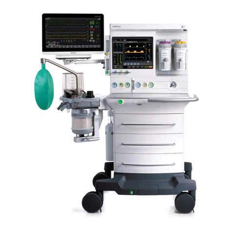
  9. Mindray A Series User manual

Mindray A Series User manual

Mindray North America 800 MacArthur Blvd. Mahwah, NJ 07430 Tel: 201.995.8000 www.mindray.com 0002-08-1659 Rev. A
Page 1 of 19
March 30, 2020
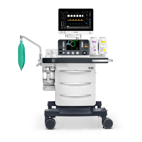
Mindray A-Series Anesthesia Delivery System
Consideration for use as a Ventilator
Addendum – Procedures for Converting Drive Gas from Oxygen to Air
Dear Valued Customer:
This communication is an addendum to the document noted above and provided on March 23, 2020 regarding
the use of Mindray A-Series Anesthesia Delivery Systems for continuous ventilation. Specifically detailed is the
process for converting the systems drive gas from oxygen to air.
Note: Only individuals qualified to perform maintenance/repair on anesthesia systems should carry
out this conversion.
Systems having the drive gas modified should be prominently labeled as such and may not be
used for anesthesia delivery, until the drive gas is reverted to oxygen.
Guidance for converting the A7 system is provided under Attachment 1.
Guidance for converting the A5 system is provided under Attachment 2.
Guidance for converting the A3/A4 system is provided under Attachment 3.
The following are recommendations/considerations during use after a system’s drive gas has been converted
from oxygen to air:
1. It is strongly recommended to connect both the air and oxygen source before using the system to achieve
a gas source pressure between 280-600 kPa (41-80 psi).
2. If the pressure of air is lower than 140 kPa ±10% (20 psi ±10%), the system will display the alarm “Drive
Gas Pressure Low” and will not ventilate.
3. If the pressure of the oxygen gas source is lower than 220 kPa ±10% (32 psi ±10%) the system will display
the alarm ”O2 Supply Failure”. Under this condition, the system will continue to ventilate but the oxygen
fresh gas delivered may be lower than expected.
4. If the flow sensor requires calibration after the drive gas has been converted, the tidal volume accuracy may
be up to 5% over specification.
Mindray’s in-house supports team remain available 24/7. If assistance is needed, please contact Technical
Support at (800) 288-2121, option 2.
Sincerely,
Diane Arpino
Director, Quality Operations and Regulatory Affairs
Mindray DS USA, Inc.
US Agent for Shenzhen Mindray Biomedical Corp., Ltd.
[email protected]
Mindray North America 800 MacArthur Blvd. Mahwah, NJ 07430 Tel: 201.995.8000 www.mindray.com 0002-08-1659 Rev. A
Page 2 of 19
Attachment 1
Please follow the steps below to convert the drive gas of Mindray A7 Anesthesia delivery systems from
oxygen to air, the connection diagrams before and after the change are shown below:
Connection diagram before change:
Connection diagram after change:
Mindray North America 800 MacArthur Blvd. Mahwah, NJ 07430 Tel: 201.995.8000 www.mindray.com 0002-08-1659 Rev. A
Page 3 of 19
1. Open the service door: Turn the two screws on the service door counter-clockwise one half turn to open
the door. (If the AGSS assembly is connected to the machine, unplug the transfer tubes from AGSS
assembly).
2. Remove the rear cover panel: Unscrew the six screws on the lower rear panel assembly to remove it.
Mindray North America 800 MacArthur Blvd. Mahwah, NJ 07430 Tel: 201.995.8000 www.mindray.com 0002-08-1659 Rev. A
Page 4 of 19
3. Remove the yoke panel: Unscrew the four screws on the upper rear panel (yoke cover) ,and pull it out.
4. Remove the hose #36
(Orange) from the AIR cylinder yoke and the X-piece (connected to hoses #54, #37
and #125).
5. Disconnect the hose #60 (Green) from the oxygen cylinder yoke.
36
60
Mindray North America 800 MacArthur Blvd. Mahwah, NJ 07430 Tel: 201.995.8000 www.mindray.com 0002-08-1659 Rev. A
Page 5 of 19
6. Disconnect hose #61 (Green) from the Y-piece (connected to hoses #69 and #38)
7. Connect one end of the hose #36 (Orange) to the oxygen cylinder yoke, the other end to Y-piece (connected
to hoses #69 and #38).
8. Interchange the port of hose #61 (Green) and #63 (Green).
61
36
60 61
63
63
61
60
Mindray North America 800 MacArthur Blvd. Mahwah, NJ 07430 Tel: 201.995.8000 www.mindray.com 0002-08-1659 Rev. A
Page 6 of 19
9. Connect the tube #60 (Green) to the Air cylinder yoke. Connect the opposite end of hose #61 (Green) to
the X-piece (connected to hoses #54, #37 and #125).
10. Reinstall the yoke panel, the rear cover panel and service door according to the steps #3, #2, #1.
11. Perform the following Pneumatic Tests:
a) Remove the O2 and AIR cylinder from the anesthesia system.
b) Connect the O2 and AIR line pressure hoses to the line pressure inlet on the anesthesia system.
c) Pinch the O2 line pressure hose.
d) Remove the O2 line pressure hose from the line source while keeping the hose pinched. The
pressure measured on the line pressure gauge on the front of the unit should not fall more than 10
psi per 100 seconds (2 psi per 20 sec).
e) Release the O2 line pressure hose.
f) Pinch the AIR line pressure hose.
g) Remove the AIR line pressure hose from the line source while keeping the hose pinched. The
pressure measured on the line pressure gauge on the front of the unit should not fall more than 10
psi per 100 seconds (2 psi per 20 sec).
h) Release the AIR line pressure hose.
i) Reconnect the O2 and AIR line pressure hoses and remove the pinch in the hose.
12. Perform the following Internal Gas Connections Test:
a) Close and remove all gas cylinders from the anesthesia system.
b) Connect only the O2 line pressure hose to the anesthesia system from the wall supply. Leave all
other line pressure hoses disconnected.
c) Turn the unit on and set the A7 in BFCS mode, Rotate the O2 needle valve knob to ensure a
continuous flow increase throughout its full range. Set the O2 flow to 2L/min.
d) Fully rotate the AIR needle valve knob and verify that there is no increase of total flow. Close the AIR
valve.
e) Disconnect the O2 line pressure hose from the anesthesia system, and connect the AIR line pressure
hose from the wall supply.
f) Rotate the AIR needle valve knob to ensure a continuous flow increase throughout its full range.
g) Set the AIR flow to 2L/min.
h) Fully rotate the O2 needle valve knob and verify that there is no increase of total flow.
61
60
Mindray North America 800 MacArthur Blvd. Mahwah, NJ 07430 Tel: 201.995.8000 www.mindray.com 0002-08-1659 Rev. A
Page 7 of 19
i) Close the AIR and O2 valves.
j) Disable Backup Flow Control.
13. Perform the following VCV Adult Ventilation Mode Test:
a) Set the Fresh Gas Control to Direct Flow Mode.
b) Set the O2 flow to 2 L/min and set the N2O and AIR flow rates to minimum flow.
c) Set the mechanical Auto/Manual switch to AUTO.
d) Connect a Vent Tester to the breathing system. Unidirectional Vent Testers need to be connected to
the expiratory limb.
e) Set the ventilator controls to the following:
i. Ventilation Mode: VCV
ii. Vt: 600
iii. Rate: 8
iv. I:E: 1:2
v. Tpause: 10
vi. PEEP: Off
vii. Plimit: 50
f) Verify that the pressure waveform, Tidal Volume, Mean or Plateau Pressure, Resp. rate and minute
volume values appear on the screen.
g) Verify the Tidal Volume display on the Vent Tester is within 12% (±72 mL) of the set value within
approximately 1 minute from the start of ventilation.
h) Verify the Tidal Volume display is within 14% (±84 mL) of the set value within approximately 1 minute
from the start of ventilation.
14. Prominently label the unit that the drive gas has been modified and the system may be used.
Please follow the steps below to convert the drive gas of Mindray A7 Anesthesia delivery systems from air to
oxygen.
1. The systems should be converted back to using oxygen as the drive gas by performing the above steps in
reverse.
2. Perform the Pneumatic Leak Tests per chapter 3.9 of the service manual
3. Perform the Internal Gas Connections Test per chapter 3.10.2 of the service manual
4. Perform a flow calibration per chapter 4.3.3 (Flow Calibration (Service)) of the service manual
5. Perform the chapter 3.11 (Performance Verification) of the service manual
6. The label that was added to the unit that the drive gas was been modified should be removed and the
system may be used for anesthesia delivery.
Mindray North America 800 MacArthur Blvd. Mahwah, NJ 07430 Tel: 201.995.8000 www.mindray.com 0002-08-1659 Rev. A
Page 8 of 19
Attachment 2
Please follow the steps below to convert the drive gas of Mindray A5 Anesthesia delivery systems from
oxygen to air. The connection diagrams before and after change are shown below:
Connection diagram before change:
Connection diagram after change:
Mindray North America 800 MacArthur Blvd. Mahwah, NJ 07430 Tel: 201.995.8000 www.mindray.com 0002-08-1659 Rev. A
Page 9 of 19
1. Open the service door: Turn the two screws on the service door counter-clockwise one half turn to open
the door (If the AGSS assembly is connected to the machine, unplug the transfer tubes from AGSS
assembly).
2. Remove the rear cover panel: Unscrew the six screws on the lower rear panel assembly to remove it.
3. Remove the yoke panel: Unscrew the four screws on the upper rear panel (yoke cover) and pull it out.
Mindray North America 800 MacArthur Blvd. Mahwah, NJ 07430 Tel: 201.995.8000 www.mindray.com 0002-08-1659 Rev. A
Page 10 of 19
4. Disconnect hose #36 (Orange) from the Y-piece (connected to hoses #54 and #37).
5. Disconnect the hose #61(Green) from the Y-piece (connected to hoses #60 and #38).
Disconnect hose #69 (Green) from the Y-piece (connected to hoses #61 and #63).
6. Connect hose #69 (Green) to the Y-piece (connected to hoses #60 and #38).
36
61
69
69
Mindray North America 800 MacArthur Blvd. Mahwah, NJ 07430 Tel: 201.995.8000 www.mindray.com 0002-08-1659 Rev. A
Page 11 of 19
7. Remove the hose #61 (Green) and connect it to the outlet of Y-piece (the side with only one outlet), connect
the hose #36 (Orange) and to another outlet of Y-piece (the side with two outlets).
8. Connect the opposite end of hose #61 (Green) to the Y-piece (connected to hoses #54 and #37).
9. Reinstall the yoke panel, rear cover panel service door and AGSS (if applicable) according to the steps #3,
#2, and #1.
10. Perform the following Pneumatic Leak Tests:
a) Remove the O2 and AIR cylinder from the anesthesia system.
b) Connect the O2 and AIR line pressure hoses to the line pressure inlet on the anesthesia system.
c) Pinch the O2 line pressure hose.
d) Remove the O2 line pressure hose from the line source while keeping the hose pinched. The
pressure measured on the line pressure gauge on the front of the unit should not fall more than 10
psi per 100 seconds (2 psi per 20 sec).
e) Release the O2 line pressure hose.
f) Pinch the AIR line pressure hose.
g) Remove the AIR line pressure hose from the line source while keeping the hose pinched. The
pressure measured on the line pressure gauge on the front of the unit should not fall more than 10
psi per 100 seconds (2 psi per 20 sec).
h) Release the AIR line pressure hose.
i) Reconnect the O2 and AIR line pressure hoses and remove the pinch in the hose.
63
61
36
63
61
61
Mindray North America 800 MacArthur Blvd. Mahwah, NJ 07430 Tel: 201.995.8000 www.mindray.com 0002-08-1659 Rev. A
Page 12 of 19
11. Perform the following Internal Gas Connections Test:
a) Close and remove all gas cylinders from the A5.
b) Connect only the AIR line pressure hose to the A5 from the wall supply. Leave all other line pressure
hoses disconnected.
c) With the A5 powered ON, rotate the AIR flow control knob to ensure a continuous flow increase
throughout its full range.
d) Fully rotate the N2O flow control knob and verify that there is no flow.
e) Fully rotate the O2 flow control knob and verify that there is no flow.
f) Disconnect the AIR line pressure hose from the A5 and connect the O2 line pressure hose from the
wall supply, rotate the O2 flow control knob to ensure a continuous flow increase throughout its full
range (0 to 15 L/min).
g) Fully rotate the N2O flow control knob and verify that there is no flow.
h) Fully rotate the AIR flow control knob and verify that there is no flow.
i) Connect the N2O line pressure hose from the wall supply. With the O2 flow control knob fully opened,
rotate the N2O flow control knob to ensure a continuous flow increase throughout its full range. Skip
this step if N2O supply is not available
j) Fully rotate the AIR flow control knob and verify that there is no flow. Skip this step if N2O supply is
not available
k) Close all 3 flow control knobs and reconnect the AIR line pressure hose.
12. Perform the following VCV Adult Ventilation Mode Test:
a) Set the O2 flow to 2 L/min and set the N2O and AIR flow rates to minimum flow.
b) Set the mechanical Auto/Manual switch to AUTO.
c) Connect a Vent Tester to the breathing system. Unidirectional Vent Testers need to be connected to
the expiratory limb.
d) Set the ventilator controls to the following:
i. Ventilation Mode: VCV
ii. Vt: 600
iii. Rate: 8
iv. I:E: 1:2
v. Tpause: 10
vi. PEEP: Off
vii. Plimit: 50
e) Verify that the pressure waveform, Tidal Volume, Mean or Plateau Pressure, Resp. rate and minute
volume values appear on the screen.
f) Verify the Tidal Volume display on the Vent Tester is within 12% (±72 mL) of the set value within
approximately 1 minute from the start of ventilation.
g) Verify the Tidal Volume display is within 14% (±84 mL) of the set value within approximately 1 minute
from the start of ventilation.
13. Prominently label the unit that the drive gas has been modified and the system may be used.
Please follow the steps below to convert the drive gas of Mindray A5 Anesthesia delivery systems from air to
oxygen.
1. The systems should be converted back to using oxygen as the drive gas by performing the above steps in
reverse.
2. Perform the Pneumatic Leak Tests per chapter 3.9 of the service manual
Mindray North America 800 MacArthur Blvd. Mahwah, NJ 07430 Tel: 201.995.8000 www.mindray.com 0002-08-1659 Rev. A
Page 13 of 19
3. Perform the Internal Gas Connections Test per chapter 3.10.2 of the service manual
4. Perform a flow calibration per chapter 4.3.3 (Flow Calibration (Service)) of the service manual
5. Perform the chapter 3.11 (Performance Verification) of the service manual
6. The label that was added to the unit that the drive gas was been modified should be removed and the
system may be used for anesthesia delivery.
Mindray North America 800 MacArthur Blvd. Mahwah, NJ 07430 Tel: 201.995.8000 www.mindray.com 0002-08-1659 Rev. A
Page 14 of 19
Attachment 3
Please follow the steps below to convert the drive gas of Mindray A3/A4 Anesthesia delivery systems from
oxygen to air (Please note the A4 doesn’t have N2O gas yoke). The connection diagrams before and after
change are shown below:
Connection diagram before change:
Connection diagram after change:
Mindray North America 800 MacArthur Blvd. Mahwah, NJ 07430 Tel: 201.995.8000 www.mindray.com 0002-08-1659 Rev. A
Page 15 of 19
1. Open the service door: Turn the two screws on the service door counter-clockwise one half turn to open
the door(If the AGSS assembly is connected to the machine, unplug the transfer tubes from AGSS
assembly)
2. Remove the rear cover panel: Unscrew the six screws on the lower rear panel assembly to remove it.
3. Remove the yoke panel: Unscrew the four screws on the upper rear panel (yoke cover) and pull it out.
Mindray North America 800 MacArthur Blvd. Mahwah, NJ 07430 Tel: 201.995.8000 www.mindray.com 0002-08-1659 Rev. A
Page 16 of 19
4. Disconnect hose #36 (Orange) from the Y-piece (connected to hoses #54 and #37).
5. Disconnect hose #60 (Green) from the Y-piece (connected to hoses #38 and #63).
Disconnect hose #38 (Green) the Y-piece (connected to hoses #79 and #81).
36
60
38
Mindray North America 800 MacArthur Blvd. Mahwah, NJ 07430 Tel: 201.995.8000 www.mindray.com 0002-08-1659 Rev. A
Page 17 of 19
6. Connect hose #60 (Green) to the Y-piece (connected to hoses #79 and #81).
7. Remove the hose #38(Green) and connect it to the outlet of Y-piece (the side with only one outlet), connect
the hose #36(Orange) and to another outlet of Y-piece (the side with two outlets).
60
38
63
38
63 36
Mindray North America 800 MacArthur Blvd. Mahwah, NJ 07430 Tel: 201.995.8000 www.mindray.com 0002-08-1659 Rev. A
Page 18 of 19
8. Connect the opposite end of hose #38 (Green)) to the Y-piece (connected to hoses #54 and #37).
9. Connect the Air/O2 pipeline supply, check if abnormal sound due to leakage occurs.
10. Reinstall the yoke panel, the rear cover panel, the service door and AGSS if applicable) according to the
steps #3, #2, # 1 in Attachment 1.
11. Perform the following Pneumatic Leak Tests:
a) Remove the O2 and AIR cylinder from the anesthesia system.
b) Connect the O2 and AIR line pressure hoses to the line pressure inlet on the anesthesia system.
c) Pinch the O2 line pressure hose.
d) Remove the O2 line pressure hose from the line source while keeping the hose pinched. The
pressure measured on the line pressure gauge on the front of the unit should not fall more than 10
psi per 100 seconds (2 psi per 20 sec).
e) Release the O2 line pressure hose.
f) Pinch the AIR line pressure hose.
g) Remove the AIR line pressure hose from the line source while keeping the hose pinched. The
pressure measured on the line pressure gauge on the front of the unit should not fall more than 10
psi per 100 seconds (2 psi per 20 sec).
h) Release the AIR line pressure hose.
i) Reconnect the O2 and AIR line pressure hoses and remove the pinch in the hose.
12. Perform the following Internal Gas Connections Test:
a. Close and remove all gas cylinders from the A3/A4.
b. Connect only the AIR line pressure hose to the A3/A4 from the wall supply. Leave all other line
pressure hoses disconnected.
c. With the A3/A4 powered ON, rotate the AIR flow control knob to ensure a continuous flow increase
throughout its full range.
d. Fully rotate the N2O flow control knob and verify that there is no flow.
e. Fully rotate the O2 flow control knob and verify that there is no flow.
f. Disconnect the AIR line pressure hose from the A3/A4 and connect the O2 line pressure hose from
the wall supply, rotate the O2 flow control knob to ensure a continuous flow increase throughout its full
range (0 to 15 L/min).
38
Mindray North America 800 MacArthur Blvd. Mahwah, NJ 07430 Tel: 201.995.8000 www.mindray.com 0002-08-1659 Rev. A
Page 19 of 19
g. Fully rotate the N2O flow control knob and verify that there is no flow.
h. Fully rotate the AIR flow control knob and verify that there is no flow.
i. Connect the N2O line pressure hose from the wall supply. With the O2 flow control knob fully opened,
rotate the N2O flow control knob to ensure a continuous flow increase throughout its full range. Skip
this step if N2O supply is not available
j. Fully rotate the AIR flow control knob and verify that there is no flow. Skip this step if N2O supply is
not available
k. Close all 3 flow control knobs and reconnect the AIR line pressure hose.
13. Perform the following VCV Adult Ventilation Mode Test:
a. Set the O2 flow to 2 L/min and set the N2O and AIR flow rates to minimum flow.
b. Set the mechanical Auto/Manual switch to AUTO.
c. Connect a Vent Tester to the breathing system. Unidirectional Vent Testers need to be connected to
the expiratory limb.
d. Set the ventilator controls to the following:
i. Ventilation Mode: VCV
ii. Vt: 600
iii. Rate: 8
iv. I:E: 1:2
v. Tpause: 10
vi. PEEP: Off
vii. Plimit: 50
e. Verify that the pressure waveform, Tidal Volume, Mean or Plateau Pressure, Resp. rate and minute
volume values appear on the screen.
f. Verify the Tidal Volume display on the Vent Tester is within 12% (±72 mL) of the set value within
approximately 1 minute from the start of ventilation.
g. Verify the Tidal Volume display is within 14% (±84 mL) of the set value within approximately 1 minute
from the start of ventilation.
14. Prominently label the unit that the drive gas has been modified and the system may be used.
Please follow the steps below to convert the drive gas of Mindray A4/A3 Anesthesia delivery systems from air
to oxygen.
1. The systems should be converted back to using oxygen as the drive gas by performing the above steps in
reverse.
2. Perform the Pneumatic Leak Tests per chapter 3.9 of the service manual
3. Perform the Internal Gas Connections Test per chapter 3.10.2 of the service manual
4. Perform a flow calibration per chapter 4.3.3 (Flow Calibration (Service)) of the service manual
5. Perform the chapter 3.11 (Performance Verification) of the service manual
6. The label that was added to the unit that the drive gas was been modified should be removed and the
system may be used for anesthesia delivery.

Other manuals for A Series

1

Other Mindray Medical Equipment manuals

Mindray DPM 4 User manual

Mindray

Mindray DPM 4 User manual

Mindray M7 User manual

Mindray

Mindray M7 User manual

Mindray BeneVision N Series 22 N1 User manual

Mindray

Mindray BeneVision N Series 22 N1 User manual

Mindray Panorama TELEPACK-608 SpO2 User manual

Mindray

Mindray Panorama TELEPACK-608 SpO2 User manual

Mindray uMEC10 User manual

Mindray

Mindray uMEC10 User manual

Mindray DC-80A User manual

Mindray

Mindray DC-80A User manual

Mindray TE7 User manual

Mindray

Mindray TE7 User manual

Mindray 115-023421-00 User manual

Mindray

Mindray 115-023421-00 User manual

Mindray WATO EX-65 User manual

Mindray

Mindray WATO EX-65 User manual

Mindray VS-900 User manual

Mindray

Mindray VS-900 User manual

Mindray Passport V User manual

Mindray

Mindray Passport V User manual

Mindray Accutorr 3 User manual

Mindray

Mindray Accutorr 3 User manual

Mindray Spectrum User manual

Mindray

Mindray Spectrum User manual

Mindray BeneFusion eSP Vet User manual

Mindray

Mindray BeneFusion eSP Vet User manual

Mindray Datascope AS 3000 User manual

Mindray

Mindray Datascope AS 3000 User manual

Mindray P7-3T User manual

Mindray

Mindray P7-3T User manual

Mindray DC-8 EXP User manual

Mindray

Mindray DC-8 EXP User manual

Mindray BeneFusion mNP User manual

Mindray

Mindray BeneFusion mNP User manual

Mindray Passport 12 User manual

Mindray

Mindray Passport 12 User manual

Mindray Resona 7 User manual

Mindray

Mindray Resona 7 User manual

Mindray TE7 User manual

Mindray

Mindray TE7 User manual

Mindray TE7T User manual

Mindray

Mindray TE7T User manual

Mindray Resona I9 User manual

Mindray

Mindray Resona I9 User manual

Mindray BeneHeart D3 User manual

Mindray

Mindray BeneHeart D3 User manual

Popular Medical Equipment manuals by other brands

Morita ROOT ZX II Operation instructions

Morita

Morita ROOT ZX II Operation instructions

Gima CMS50Q1 manual

Gima

Gima CMS50Q1 manual

Nutricia FLOCARE INFINITY II Instructions for use

Nutricia

Nutricia FLOCARE INFINITY II Instructions for use

Siemens MTCO 1324 operating instructions

Siemens

Siemens MTCO 1324 operating instructions

Belluscura SLYDE 6400-000-000 Operation manual

Belluscura

Belluscura SLYDE 6400-000-000 Operation manual

Albrecht CDS WRIST BRACE EXTENSION User instructions

Albrecht

Albrecht CDS WRIST BRACE EXTENSION User instructions

Bausch & Lomb MISTER SPEX TRUE LENS PREMIUM Instructions for use

Bausch & Lomb

Bausch & Lomb MISTER SPEX TRUE LENS PREMIUM Instructions for use

Arjo Alenti quick start guide

Arjo

Arjo Alenti quick start guide

Olympus MAJ-2414 instructions

Olympus

Olympus MAJ-2414 instructions

Olympus EVIS EXERA TJF-160VR instructions

Olympus

Olympus EVIS EXERA TJF-160VR instructions

Emerson Albr BDS-256XL Specification sheet

Emerson

Emerson Albr BDS-256XL Specification sheet

Hallowell EMC 2002PRO operating manual

Hallowell EMC

Hallowell EMC 2002PRO operating manual

Maquet VASOVIEW 7 Training manual

Maquet

Maquet VASOVIEW 7 Training manual

Ypsomed mylife YpsoPump user guide

Ypsomed

Ypsomed mylife YpsoPump user guide

MiraMate Mini Magic instructions

MiraMate

MiraMate Mini Magic instructions

Otto Bock 4R98 Instructions for use

Otto Bock

Otto Bock 4R98 Instructions for use

Handicare SystemRoMedic EasyBelt user manual

Handicare

Handicare SystemRoMedic EasyBelt user manual

Riester ri-fox N Operator's manual

Riester

Riester ri-fox N Operator's manual

manuals.online logo
manuals.online logoBrands
  • About & Mission
  • Contact us
  • Privacy Policy
  • Terms and Conditions

Copyright 2025 Manuals.Online. All Rights Reserved.