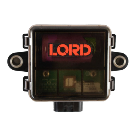
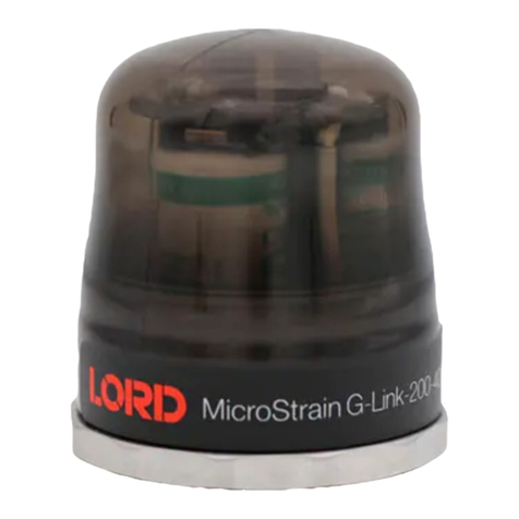
Lord MicroStrain G-Link-LXRS User manual

LORD USERMANUAL
G-Link®-LXRS®
Wireless Accelerometer Node

MicroStrain®Sensing Systems
459 Hurricane Lane
Suite 102
Williston, VT 05495
United States of America
Phone: 802-862-6629
Fax: 802-863-4093
http://www.microstrain.com
sensing_support@LORD.com
sensing_sales@LORD.com
Copyright © 2015 LORD Corporation
3DM®, 3DM-DH®, 3DM-DH3™, 3DM-GX1®, 3DM-GX2®, 3DM-GX3®, 3DM-GX4-15™, 3DM-GX4-25™, 3DM-GX4-45™,
3DM-GX4™, 3DM-RQ1™, AIFP®, Ask Us How™, Bolt-Link®, DEMOD-DC®, DVRT®, DVRT-Link™, EH-Link®,
EmbedSense®, ENV-Link™, FAS-A®, G-Link®, G-Link2™, HS-Link®, IEPE-Link™, Inertia-Link®, Little Sensors, Big Ideas.®,
Live Connect™, LXRS®, MathEngine®, MicroStrain®, MVEH™, MXRS®, Node Commander®, PVEH™, RHT-Link®, RTD-
Link™, SensorCloud™, SG-Link®, Shock-Link™, Strain Wizard®, TC-Link®, Torque-Link™, V-Link®, Watt-Link™, Wireless
Simplicity, Hardwired Reliability™, and WSDA®are trademarks of LORD Corporation.
Document 8500-0002 Revision C
Subject to change without notice.

G-Link®-LXRS®Wireless Accelerometer Node User Manual
Table of Contents
1. Wireless Sensor Network Overview 6
2. Node Overview 7
2.1 Components List 8
2.2 Interface and Indicators 9
3. System Operational Overview 10
3.1 Software Installation 11
3.2 System Connections 12
3.3 Gateway USB Communication 13
3.4 Connect to Nodes 14
3.4.1 Adding a Node by Address 14
3.4.2 Using Node Discovery 14
3.5 Channel Configuration 16
3.6 Sampling Settings 18
3.7 Data Acquisition 19
3.8 Data Handling 24
3.9 Connect to SensorCloud™ 25
3.9.1 Sensor Data Files 28
4. Node Installation 29
4.1 Mounting Recommendations 29
4.2 Sensor Frame 30
4.3 Optimizing the Radio Link 31
4.3.1 Range Test 32
5. Powering the Node 33
5.1 Selecting the Power Source 33

G-Link®-LXRS®Wireless Accelerometer Node User Manual
5.2 Using the Internal Node Battery 34
5.3 Charging the Node Battery 35
5.4 Connecting an External Power Supply 36
6. Sensor Settings and Operation 37
6.1 Node Channels Designations 37
6.2 Measurement Units 38
6.3 Conversion Values 39
6.4 Operational Considerations 41
6.4.1 Measurement Range 41
6.4.2 Node Sampling Rates 41
6.4.3 Gravity Offset 41
6.5 On-board Temperature Sensor 42
7. Troubleshooting 43
7.1 Troubleshooting Guide 43
7.2 Device Status Indicators 48
7.3 Updating Node Firmware 49
7.4 Repair and Calibration 51
7.5 Technical Support 52
8. Maintenance 53
9. Parts and Configurations 54
9.1 Standard Nodes 54
9.2 Node Accessories 55
9.3 Wireless System Equipment 56
9.4 Product Ordering 57
10. Specifications 58

G-Link®-LXRS®Wireless Accelerometer Node User Manual
10.1 Physical Specifications 58
10.2 Operating Specifications 60
10.3 Power Profile 62
10.4 Radio Specifications 63
11. Safety Information 64
11.1 Battery Hazards 64
11.2 User Configurable Power Settings 65
11.3 Power Supply 66
11.4 ESD Sensitivity 66
12. References 67
12.1 Reference Information 67
12.2 Glossary 68

G-Link®-LXRS®Wireless Accelerometer Node User Manual System Overview
6
1. Wireless Sensor Network Overview
The LORD MicroStrain ®Wireless Sensor Network is a high- speed, scalable, sensor data
acquisition and sensor networking system. Each system consists of wireless sensor interface
nodes, a data collection gateway, and full-featured user software platforms based on the LORD
MicroStrain®Lossless Extended Range Synchronized (LXRS®) data communications protocol.
Bidirectional wireless communication between the node and gateway enables sensor data
collection and configuration from up to two kilometers away. Gateways can be connected locally to
a host computer or remotely via local and mobile networks. Some gateways also feature analog
outputs for porting sensor data directly to standalone data acquisition equipment.
The selection of available nodes allows interface with many types of sensors, including
accelerometers, strain gauges, pressure transducers, load cells, torque and vibration sensors,
magnetometers, 4 to 20mA sensors, thermocouples, RTD sensors, soil moisture and humidity
sensors, inclinometers, and orientation and displacement sensors. Some nodes come with
integrated sensing devices such as accelerometers. System sampling capabilities are IEEE
802.15.4-compliant and include lossless synchronized sampling, continuous and burst sampling,
and data logging. A single gateway can coordinate many nodes of any type, and multiple gateways
can be managed from one computer with the Node Commander®and SensorCloud™ software
platforms. Integration to customer systems can be accomplished using OEM versions of the
sensor nodes and leveraging the LORD MicroStrain®data communications protocol.
Common wireless applications of LORD MicroStrain ®Sensing Systems are strain sensor
measurement, accelerometer platforms, vibration monitoring, energy monitoring, environmental
monitoring, and temperature monitoring.

G-Link®-LXRS®Wireless Accelerometer Node User Manual Node Overview
7
2. Node Overview
The G-Link®-LXRS®wireless sensor node features two integrated high-speed ± 2 gor ± 10 g
micro-electro- mechanical (MEMS) accelerometers and an internal temperature sensor. The
combined readings from the accelerometers produce a triaxial acceleration output. The node has
12-bit resolution with a measurement bandwidth of 0 to 500 Hz. The node can log data to internal
memory and transmit real-time, synchronized data at a wide range of sample rates and intervals.
To acquire sensor data, the G-Link -LXRS is used with a LORD MicroStrain data gateway such as
the WSDA®-Base or WSDA®-1500 - LXRS®.
Figure 1 - G-Link®-LXRS®Wireless Accelerometer Node

G-Link®-LXRS®Wireless Accelerometer Node User Manual Node Overview
8
2.1 Components List
The G-Link®-LXRS®sensors and antenna are integrated so there are no external components
or removable parts. The node requires a power supply for charging the internal battery and is
purchased separately. For a complete list of available configurations, accessories, additional
system products and ordering information see Parts and Configurations on page 54.
Item Description Quantity
AG-Link®-LXRS®Wireless Accelerometer Node 1
-- Charging power supply with plug adapter kit (optional) 1
-- User Manual, Quick Start Guide and Calibration Certificate 1
Table 1 - Node Components List

G-Link®-LXRS®Wireless Accelerometer Node User Manual Node Overview
9
2.2 Interface and Indicators
The G-Link®-LXRS®includes a power input jack for charging the internal battery or externally
powering the node, a power on/off switch, a power source selector switch, and mounting holes
for device installation. The radio frequency (RF) antenna is internal to the node.
The indicators on the G-Link®-LXRS®include a device status indicator, a battery charging
indicator, a completed charge indicator, and a charge source indicator . The following table
describes basic indicator behavior. During data acquisition, the device status indicator has
other sequences (see Device Status Indicators on page 48).
Figure 2 - Interface and Indicators
Indicator Symbol Behavior Node Status
Battery charge
source indicator
OFF No power source detected
ON green Charging source detected
Battery charging
indicator
OFF Node not charging
ON bright red Node battery charging
Completed
charge indicator
OFF Node charge status unknown
ON green Battery fully charged
Device status
indicator
OFF Node OFF
Rapid flashing Node booting up
1 second pulse Node active and idle
Table 2 - Indicator Behaviors

G-Link®-LXRS®Wireless Accelerometer Node User Manual System Operational Overview
10
3. System Operational Overview
The G- Link ®- LXRS ®contains an internal, rechargeable
Lithium Polymer (Li-Po) battery. For important precautions
see Safety Information on page 64.
The G- Link ®- LXRS ®is susceptible to damage and/or
disruption of normal operation from Electrostatic Discharge
(ESD). For important precautions see Safety Information on
page 64.
To acquire sensor data, nodes are used with any LORD MicroStrain®data gateway, such as the
WSDA®-Base -10x-LXRS®or WSDA®-1500 - LXRS®, and a software interface.
LORD MicroStrain ®has two software programs available for the Wireless Sensor Network:
SensorCloud™ and Node Commander ®. SensorCloud™ is an optional web- based data
collection, visualization, analysis, and remote management platform based on cloud computing
technology. Node Commander®is used for configuring gateways and nodes, selecting sampling
modes and parameters, initializing data acquisition, and viewing and saving data.
In this section system hardware and software setup is described, including an overview of the
Node Commander®software menus required to configure a sensor connected to the node and
begin data acquisition through the gateway. It is intended as a quick start guide and is not a
complete demonstration of all system or software features, capabilities, or settings. Refer to the
Node Commander®User Manual, the LORD MicroStrain ®website, and the SensorCloud™
website for more information (see References on page 67).

G-Link®-LXRS®Wireless Accelerometer Node User Manual System Operational Overview
11
3.1 Software Installation
To install Node Commander ®Software Suite on the host computer, run the installer
executable file and follow the on-screen prompts for a complete installation. The software is
provided with all gateways and is available on the LORD MicroStrain ®website ( see
References on page 67).
NOTE
The Node Commander®software includes hardware drivers required for use
with USB gateways. Once installed, the software will automatically detect and
configure any USB gateways that are plugged into the host computer.
The suite includes the following programs:
lNode Commander is used for configuring nodes and acquiring, viewing, and
saving data.
lLive Connect™is a TCP/IP-to-serial conversion tool that translates the
communications between Node Commander and an Ethernet gateway.
lWSDA®Data Downloader is used to download acquired data from the flash
memory card embedded in an applicable gateway to a host computer.
SensorCloud™ is an optional data collection, visualization, analysis, and remote
management tool. It is based on cloud computing technology and is accessed directly from a
web connection. Automatic, real- time data collection is available through Ethernet
gateways, such as the WSDA®-1500 - LXRS®and any already collected data can be easily
uploaded for visualization and analysis. Because it is web-based, SensorCloud™ requires
no installation. For more information see Data Handling on page 24.
Users can also design custom programs with the open source data communications
protocol (see References on page 67).

G-Link®-LXRS®Wireless Accelerometer Node User Manual System Operational Overview
12
3.2 System Connections
To acquire sensor data the following components are needed in addition to the node: a LORD
MicroStrain®data gateway and a local or networked host computer with access to the data
acquisition software (such as Node Commander ®and SensorCloud™). For a connections
overview refer to Figure 3 - System Connections .
Nodes will communicate with any LORD MicroStrain®data gateway. The sensor, node,
gateway, and software selection is application- dependent, but the basic interfaces are the
same. Communication protocols between the gateway and host computer vary depending on
which model gateway is used, but they all require interface to a host computer or network.The
WSDA®-Base -10x-LXRS®gateway utilizes local serial connections to the host computer,
such as RS232 and USB, and interfaces with the Node Commander®software. The WSDA®-
1500 - LXRS ®gateway utilizes Ethernet communications and can be used with Node
Commander®and SensorCloud™, although system configuration is completed using Node
Commander®. Gateways with analog outputs can be connected directly to stand-alone data
acquisition devices for data collection, however system configuration will still occur through a
USB interface to Node Commander®.
Users can also write custom programs by utilizing the LORD MicroStrain®Wireless Sensors
Network Software Development Kit (see References on page 67).
Figure 3 - System Connections

G-Link®-LXRS®Wireless Accelerometer Node User Manual System Operational Overview
13
3.3 Gateway USB Communication
The WSDA-Base USB gateway is used as an example in this quick start guide. For information
on how to use other gateways, refer to the gateway or Node Commander®user manual (see
References on page 67).
Drivers for the USB gateways are included the Node Commander®software installation. With
the software is installed, the USB gateway will be detected automatically whenever the
gateway is plugged in.
1. Power is applied to the gateway through the USB connection. Verify the gateway
status indicator is illuminated, showing the gateway is connected and on.
2. Open the Node Commander software.
3. The gateway should appear in the Controller window automatically, with a
communication port assignment (Figure 4 - USB Gateway Communication). If it is not
automatically discovered, verify the port is active on the host computer, and then
remove and re-insert the USB connector.
Figure 4 - USB Gateway Communication

G-Link®-LXRS®Wireless Accelerometer Node User Manual System Operational Overview
14
3.4 Connect to Nodes
Several methods can be used in Node Commander®to establish communication with the
nodes. This quick start section covers the two simplest methods; adding a node by address and
by using the node discovery feature.
3.4.1 Adding a Node by Address
Adding a node by address requires the node to be on the same communication frequency
as the gateway. The node address and frequency are indicated in the documentation
included with the node when it is purchased.
1. To add a node by address, right-click on the gateway name in the Controller window,
and select Add Node > Add Single Node (Figure 5 - Adding a Node by Address).
2. The node address and frequency are indicated in the documentation included with
the node when it is purchased. Enter the node address, and select OK. If the node is
not found, a message will appear and provide the option to scan for the node on other
frequencies. Alternately, the Node Discovery feature can be used.
Figure 5 - Adding a Node by Address
3.4.2 Using Node Discovery
The Node Discovery feature allows connection between the gateway and node to occur
even if they are on different frequencies. To connect to nodes using node discovery, begin
by making sure the node(s) are powered off.

G-Link®-LXRS®Wireless Accelerometer Node User Manual System Operational Overview
15
NOTE
Automatic node discovery may not work in some boot-up modes. If the node is
not in normal boot up mode, the assigned one can be bypassed to enable node
discovery. For more information see Troubleshooting on page 43.
1. Right-click on the gateway name and select Add Node > Node Discovery (Figure 6 -
Using Node Discovery).
2. Turn on the node with the node power switch.Within a few seconds during power-up,
the node will transmit a message with its operating frequency.
3. When the device status indicator on the node ends the rapid flash sequence and
begins pulsing at one- second intervals, it has completed the normal boot- up
sequence and is running in idle mode. At this point the node should be listed in the
Controller window, and scanning can be stopped by selecting the Stop button in the
Node Discovery window.
Figure 6 - Using Node Discovery

G-Link®-LXRS®Wireless Accelerometer Node User Manual System Operational Overview
16
3.5 Channel Configuration
The sensor settings are stored in the node memory and each sensor is assigned a
corresponding channel number. Only the channels and configuration options that are
available on the type of node being used will appear in the configuration menus.
1. To enter the configuration menu, right-click on the node name, and select Configure >
Configure Node. The Channels tab displays channel options available for the node.
a. Channel Enabled: indicates the sensor channel number. The check box
is used to enable the channel and select it for sampling. The icon next to
the check box describes the channel type inherentto the node being used.
b. Current channel configuration: The Data Output, Units, Input Range,
and Label fields describe how the channel is currently configured.
c. Configure: Select the channel's Configure button to change the channel
parameters, such as measurement units, gain and offset settings, and
calibration values.The channel must be enabled first by selecting its
adjacent check box.
Figure 7 - Node Channels Menu

G-Link®-LXRS®Wireless Accelerometer Node User Manual System Operational Overview
17
2. To enter the channel configuration menu, select the Configure button as shown in
Figure 7 - Node Channels Menu. The channel configuration menu options change
depending on the sensor type selected.
a. Channel Label: names the channel
b. Channel diagram: shows channel electronics and data flow
c. Conversion Coefficients: defines the type and units of the
measurement being made
d. Sensor Slope: is the sensor sensitivity value used to convert sensor
voltage reading to engineering units. For the G-Link -LXRS this value is
provided from the factory calibration.
e. Conversion Formula and Effective Range: is the formula used to
convert sensor readings to engineering units. It also shows the resulting
sensor measurement range.
Figure 8 - Channel Setup

G-Link®-LXRS®Wireless Accelerometer Node User Manual System Operational Overview
18
3.6 Sampling Settings
Sampling settings are accessed through the Configure Node menu. There is a tab for each
sampling mode available for the particular node (Figure 9 - Sample Settings Menu).The G-
Link®-LXRS®has four primary sampling modes: Synchronized Sampling, Low Duty Cycle
Sampling, Streaming, and Datalogging. Some modes have user-configurable settings for
sample rate, sample duration, and datalogging. Other settings are automatic, depending on
number of active channels and other variables. For more information on sampling modes
refer to the Node Commander user manual (see References on page 67).
NOTE
Streaming mode (which enables continuous sampling and transmitting) uses a
large amount of system bandwidth and can significantly reduce node battery
life. Streaming is recommended primarily for diagnostics and is not supported in
SensorCloud™.
In general, when determining which sample mode and rate is most suitable for the
application, consider the following:
lIncreasing the sample rate or duration reduces the available over- the- air
transmission bandwidth and therefore also reduces the number of nodes that can be
reporting simultaneously.
lIncreasing the sample rate or duration increases the power requirement of the node
and therefore reduces the node's battery life.
lWhen measuring vibration or other analog signals, it is important to use a sample rate
at least twice the value of the target measurement frequency. This is the minimum
sample rate required to produce an accurate digital representation of the measured
signal. The higher the sample rate, the more accurate the digital representation.

G-Link®-LXRS®Wireless Accelerometer Node User Manual System Operational Overview
19
Figure 9 - Sample Settings Menu
3.7 Data Acquisition
NOTE
Once sampling has started it will continue as configured without the need to
leave Node Commander®open. However, if the node is powered off and is not
configured to sample on boot- up, data acquisition will end and must be
restarted in Node Commander®.
When data acquisition is started, each of the sampling modes has different menu options and
views. Some open a settings menu before data acquisition begins and may include a data list
view and/or a graph view. The following is an example of Synchronized Sampling (Figure 10 -
Starting a Sampling Session). For more information about synchronized sampling and using
the gateway beacon see Data Acquisition on page 19. For more information about other
sampling modes, refer to the Node Commander®user manual. (see References on page 67).
To start a sampling session, nodes can be selected individually or as a group. When selected
as a group, they will all be set to the same sampling mode. Right-click on the nodes and select
Sample > Synchronized Sampling.

G-Link®-LXRS®Wireless Accelerometer Node User Manual System Operational Overview
20
Figure 10 - Starting a Sampling Session
When a synchronized sampling session is started, the sampling menu appears and includes
settings to enable optional sampling features, configure nodes, and to specify where the data
will be saved. The built-in bandwidth calculator displays the total bandwidth used by the nodes
selected for synchronized sampling (Figure 11 - Synchronized Sampling Menu).
a. Save Location: indicates where the data file will be saved on the host computer.
Use the Browse button to select a preferred location.
b. Node configuration: includes the node serial number, sampling settings,
bandwidth calculation, and current status. Highlight any node or group of nodes,
and the Remove, Configure, and Refresh buttons become active. The Configure
button opens the node configuration menus to adjust settings as needed and
recalculates the node bandwidth. Multiple nodes can be configured together by
using the Shift or Ctrl key to select them.
c. Lossless: enables the lossless data protocol. The protocol enables buffering and
retransmission of data in order to provide 100% data collection success. Using this
feature may increase data display latency.
Table of contents
Other Lord MicroStrain Network Hardware manuals