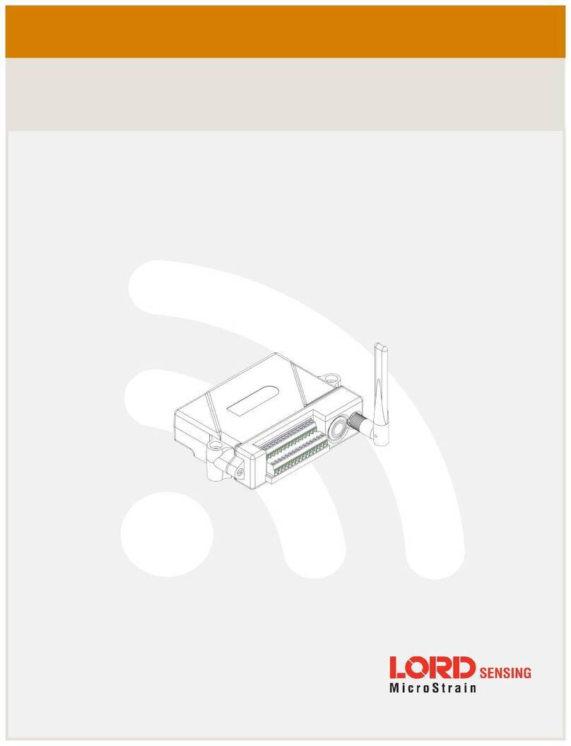
Lord MicroStrain Sensing SG-Link-200 User manual

LORD Sensing USER MANUAL
SG-Link®-200
Wireless Analog Input Node

SG-Link®-200
User Manual
Contents
1. Wireless Sensor Network Overview ..........................................................................................................5
2. Node Overview .........................................................................................................................................6
2.1 Configuration Options .............................................................................................................................7
2.2 Interface and Indicators .........................................................................................................................10
Figure 2 –..................................................................................................................................................10
Interface and Indicators............................................................................................................................10
2.3 Node Operational Modes ..................................................................................................................11
Figure 3 - Node Operational Modes .........................................................................................................11
3. Connect to Gateway and Nodes ............................................................................................................12
3.1 Software Installation ..............................................................................................................................12
http://www.microstrain.com/software ........................................................................................................12
3.2 Connect to Gateway .........................................................................................................................13
Figure 4 - USB Gateway Communication .................................................................................................13
3.3 Connect to Nodes ..................................................................................................................................14
i. Automatic Node Discovery on Same Frequency...................................................................................14
Figure 5 - Node Discovered On Same Frequency ....................................................................................14
Figure 6 - Node On Other Frequency .......................................................................................................14
Figure 7 - Move Node...............................................................................................................................15
Figure 8 - Add Node By Address ..............................................................................................................16
Figure 9 - Add Node Confirmation ............................................................................................................16
Figure 10 - Failure to Add Node ...............................................................................................................17
4. Wireless Sensor Configuration ...............................................................................................................18
4.1 Hardware Configuration .........................................................................................................................18
Figure 11 - Hardware Configuration Menu................................................................................................18
4.2 Calibration Configuration..................................................................................................................20
Figure 12 - Wireless Sensor Calibration Menu .........................................................................................20
4.3 Sampling Configuration .........................................................................................................................20
Figure 13 - Sampling Configuration Menu ................................................................................................20
4.4 Power ....................................................................................................................................................22
Figure 14 - Node Configuration Power Menu............................................................................................22
5. Wireless Sensor Sampling Configuration .............................................................................................23
5.1 Start Collecting Data.........................................................................................................................23
Figure 15 - Single Node Sampling............................................................................................................23
Figure 16 - Network of Nodes Sampling ...................................................................................................23
5.2 Network Options ....................................................................................................................................24
5.2 Derived Output Channels..................................................................................................................25

SG-Link®-200
User Manual
5.4 Sampling Operations Options ...........................................................................................................25
Figure 18 - Sampling Operations Menu....................................................................................................25
Figure 19 - Event Triggered Sampling......................................................................................................26
5.5 Output Operation ...................................................................................................................................27
Figure 20 - Data Outputs ..........................................................................................................................27
6. Data Handling..........................................................................................................................................28
6.1 SensorCloud .....................................................................................................................................29
Figure 21 - SensorCloud Log-in or Register .............................................................................................29
Figure 22 - SensorCloud Menu Views ......................................................................................................29
Figure 23 - SensorCloud Data View .........................................................................................................30
6.2 SensorConnect .................................................................................................................................32
6.2.1 Using Dashboards and Widgets ......................................................................................................32
Figure 26 - Viewing Data..........................................................................................................................32
6.2.2 Navigating Graphs...........................................................................................................................32
6.2.3 Widgets Options..............................................................................................................................33
Figure 27 - Widget Settings Menu ............................................................................................................33
6.2.4 Time Series Widget Menu ...............................................................................................................33
Figure 28 - Time Series Widget Menu ......................................................................................................33
6.2.5 Exporting Data Files .......................................................................................................................34
Figure 29 - Exporting Data .......................................................................................................................34
7. Installation................................................................................................................................................35
7.1 Mounting Recommendations .................................................................................................................35
.................................................................................................................................................................35
Figure 30 - Mounting the Node .................................................................................................................35
7.2 Range Test .......................................................................................................................................37
Figure 31 - Range Test Menu...................................................................................................................37
Figure 32 - Range Test Statistics .............................................................................................................37
8. Troubleshooting .......................................................................................................................................38
8.1 Troubleshooting Guide ..........................................................................................................................38
8.2 Updating Node Firmware.......................................................................................................................41
8.3 Repair and Calibration ......................................................................................................................42
General Instructions .................................................................................................................................42
Warranty Repairs .....................................................................................................................................42
Non-Warranty Repairs .............................................................................................................................42
9. Specifications .........................................................................................................................................43
a. Physical Specifications.........................................................................................................................43
b. Operating Specifications ......................................................................................................................44
10. Safety Information ..............................................................................................................................45

SG-Link®-200
User Manual
a. Powering the Node ...............................................................................................................................45
b. ESD Sensitivity.....................................................................................................................................45
c. Disposal and Recycling ........................................................................................................................45
d. Radio Specifications .............................................................................................................................46
11. References ..........................................................................................................................................47
http://www.microstrain.com/support/documentation .................................................................................47
Product Ordering......................................................................................................................................48
http://www.microstrain.com/wireless.........................................................................................................48
Sales Support..............................................................................................................................................48
a. Related Documents..............................................................................................................................48
Table 7 - Related Documents...................................................................................................................48
12. Glossary...................................................................................................................................................50

SG-Link®-200
User Manual
5
1. Wireless Sensor Network Overview
The LORD Sensing Wireless Sensor Network is a high- speed, scalable, sensor data acquisition and
sensor networking system. Each system consists of wireless sensor interface nodes, a data collection
gateway, and full- featured user software platforms based on the LORD Sensing Lossless Extended
Range Synchronized (LXRS and LXRS+) data communications protocols. Bi-directional wireless
communication between the node and gateway enables sensor data collection and configuration from up
to two kilometers away. Gateways can be connected locally to a host computer or remotely via local and
mobile networks. Some gateways also feature analog outputs for porting sensor data directly to stand-
alone data-acquisition equipment.
The selection of available nodes allows interface with many types of sensors, including accelerometers,
strain gauges, pressure transducers, load cells, torque and vibration sensors, magnetometers, 4 to 20 mA
sensors, thermocouples, RTD sensors, soil moisture and humidity sensors, inclinometers, and
displacement sensors. Some nodes come with integrated sensing devices such as accelerometers.
System sampling capabilities include lossless synchronized sampling, continuous and periodic burst
sampling, and data logging. A single gateway can coordinate many nodes of any type, and multiple
gateways can be managed from one computer with the SensorConnect™ and SensorCloud™ software
platforms. Integration to customer systems can be accomplished using OEM versions of the sensor nodes
and leveraging MSCL, an open source communication library.
Common wireless applications of LORD Sensing Systems are strain sensor measurement,
accelerometer platforms, vibration monitoring, energy monitoring, environmental monitoring, and
temperature monitoring.

SG-Link®-200
User Manual
6
2. Node Overview
The SG-Link-200 is a small, wireless, low-cost, three-channel analog input sensor node ready for
system integration. Featuring three differential input channels and an internal temperature sensor, the
SG-Link-200 enables high resolution, low noise data collection at sample rates up to 1 kHz. Users can
easily program nodes for continuous, periodic burst and event-triggered sampling with
SensorConnect™
Other features of the SG-Link-200 include an adjustable PGA, digital low pass filter, flash memory, and
automatic strain gauge calibration using on-board shunt resistors. This wireless sensor is ideal for
interfacing to many sensor types including strain gauge, pressure transducers, load cells and
displacement sensors.
To acquire sensor data, the SG-Link-200 is used with a LORD Sensing WSDA gateway.
Figure 1 - SG-Link-200

SG-Link®-200
User Manual
7
2.1 Configuration Options
SG-Link-200 sensor node comes with the following configuration options.
Antenna Configuration
Factory Installed Bridge
Completion
Part
Number
Integrated chip antenna
Full-bridge 6308-4200
Half-bridge, 1000 Ohms 6308-4310
Half-bridge, 350 Ohms
6308-4330
Half-bridge, 120 Ohms
6308-4320
Quarter-bridge, 1000 Ohms
6308-4410
Quarter-bridge, 350 Ohms
6308-4430
Quarter-bridge, 120 Ohms
6308-4420
U.FL interface
Full-bridge
6308-4201
Half-bridge, 1000 Ohms
6308-4311
Half-bridge, 350 Ohms
6308-4331
Half-bridge, 120 Ohms
6308-4321
Quarter-bridge, 1000 Ohms
6308-4411
Quarter-bridge, 350 Ohms
6308-4431
Quarter-bridge, 120 Ohms
6308-4421
Table 1 - SG-Link-200 Configuration Options

SG-Link®-200
User Manual
10
2.2 Interface and Indicators
Figure 2 –
Interface and Indicators
Indicator
Behavior
Node Status
Device
status
indicator
OFF
Node is OFF
Rapid green flashing
on start-up
Node is booting up
1 (slow) green pulse
per second
Node is idle and waiting
for a command
1 green blink every 2
seconds
Node is sampling
Blue LED during
sampling
Node is resynchronizing
Red LED
Built-in test error
Table 2 - Indicator Behaviors

SG-Link®-200
User Manual
11
2.3 Node Operational Modes
Sensor nodes have three operational modes:
active
,
sleep
, and
idle
. When the node is sampling, it is in
active mode. When sampling stops, the node is switched into idle mode, which is used for configuring
node settings, and allows toggling between sampling and sleeping modes. The node will automatically
go into the ultra low-power sleep mode after a user-determined period of inactivity. The node will not
go into sleep mode while sampling.
Figure 3 - Node Operational Modes

SG-Link®-200
User Manual
12
3. Connect to Gateway and Nodes
3.1 Software Installation
Install the SensorConnect software on the host computer before connecting any hardware. Access the
free software download on the LORD Sensing website at:
http://www.microstrain.com/software
SensorCloud is an optional data collection, visualization, analysis, and remote management tool. It is
based on cloud computing technology and is accessed directly from a web connection. For more
information go to: http://www.sensorcloud.com/.

SG-Link®-200
User Manual
13
3.2 Connect to Gateway
Drivers for the USB gateways are included the SensorConnect software installation. With the
software installed, the USB gateway will be detected automatically whenever the gateway is plugged
in.
1. Power is applied to the gateway through the USB connection. Verify the gateway status
indicator is illuminated, showing the gateway is connected and powered on.
2. Open the SensorConnect™software.
3. The gateway should appear in the Controller window automatically with a communication
port assignment. If the gateway is not automatically discovered, verify the port is active on the
host computer, and then remove and re-insert the USB connector.
Figure 4 - USB Gateway Communication

SG-Link®-200
User Manual
14
3.3 Connect to Nodes
Several methods can be used in SensorConnect to establish communication with the nodes: the
automatic node discovery on the same frequency, automatic node discovery on a different frequency,
and add node manually.
i. Automatic Node Discovery on Same Frequency
If the base and node are on the same operating frequency, the node will populate below the
Base Station listing when powering on the SG-Link-200.
Figure 5 - Node Discovered On Same Frequency
ii. Automatic Node Discovery on Different Frequency
If a red circle with a number appears next to the Base Station, the node may be operating on a
separate radio channel. Select the Base Station and then select the Nodes on Other
Frequencies tile.
Figure 6 - Node On Other Frequency

SG-Link®-200
User Manual
15
Highlight the new node being added and select Move Node to Frequency (#).
Figure 7 - Move Node

SG-Link®-200
User Manual
16
iii. Manually Add Node
Adding a node manually requires entering the node address and its current frequency setting.
Figure 8 - Add Node By Address
If the node was successfully added, two confirmation messages will appear, and it will be
listed under the Base Station.
Figure 9 - Add Node Confirmation

SG-Link®-200
User Manual
17
If the node failed to be added, a failure message will appear. This means the node did not
respond to the base station which could indicate the node is not in idle mode or it may be on
another frequency. If "Add Node Anyway" is selected, it will associate that node with the
channel entered but it is likely there will be a communication error. If the node was not in idle,
move the base station to the frequency of the node and issue a "Set to Idle" command.
Figure 10 - Failure to Add Node

SG-Link®-200
User Manual
18
4. Wireless Sensor Configuration
4.1 Hardware Configuration
Node settings are stored to non-volatile memory and may be configured using SensorConnect. This
chapter describes the user-configurable settings.
Figure 11 - Hardware Configuration Menu
l
Excitation Voltage
-Setthevoltageof the "SensorPower"output. Usethehighest voltage
forbestresolution.Usethelowestvoltagefor longerbatterylifeandtoreduceself-heating
of 120-Ohm strain gauges.
l
Input Range
-Settheprogrammablegainamplifier(PGA)tolimit thesensorinputrange.
Increasing gain will increase signal resolution, while decreasing gain will allow a larger input
range.

SG-Link®-200
User Manual
19
l
Low Pass Filter -
A SINC4 digital low pass filter isused toreduce noise. Set the filter toa
high frequency for a fast settling time and longest battery life. Set the filter to a lower
frequency for reduced noise at the costof alongersettlingtime.Slowerfiltersettings
may not be available at the fastest sampling rates.

SG-Link®-200
User Manual
20
4.2 Calibration Configuration
Analog channels may be independently calibrated with linear calibration coefficients. Use the "Cal
Tools" wizard for easy calibration for strain gauges or mV/V sensors, or output raw units such as volts
and ADC counts.
Figure 12 - Wireless Sensor Calibration Menu

SG-Link®-200
User Manual
20
4.3 Sampling Configuration
There are four user-set sampling options for the SG-Link-200, including Lost Beacon Timeout,
Diagnostic Info Interval, Storage Limit Mode, and Sensor Warmup Delay in the Wireless
Node Configuration > Sampling menu.
Figure 13 - Sampling Configuration Menu
l
Lost Beacon Timeout
-Whenthenodeisrunning inasynchronizednetwork,itperiodically
synchronizesitstimeclocktoabeaconbroadcastedfromtheWSDA gateway.TheLost
Beacon Timeout feature means that the node will automatically stop sampling and
transmitting data after thebeaconhasbeenlost fortheconfigured amount oftime.The
nodewillsavepowerinthisstatewithoutuserinterventionuntilthebeaconreturns.Within
two minutes of the beacon returning, the node will automatically begin sampling and
transmitting dataagain.
l
Diagnostic Info Interval
-Atthedefinedtransmitinterval, thewireless sensor willreport
diagnostic information. The node will continue to transmit this diagnostic information in all
operating modes, includingIdle, Sleep, and Run modes. (
See Table 3- below
).
l
Storage Limit Mode -
The Storage LimitMode applieswhenthe node isdataloggingto
internal flash. The two available options are: 1)
Stop -
when the node fills up its flash
memory,itwillstoploggingdata. Itisimportanttoeraseolddatabeforestartingnew data
loggingsessions, and2)
Overwrite -
whenthenodefillsupitsflashmemory,newdatawill
overwrite old data in a first-in, first-out method.
l
Sensor Warmup Delay
-Leavethesensorexcitationoncontinuouslyor duty-cyclepower
tothesensorinordertosavepower.Whendutycyclingpowertothesensors,assurethe
sensor signalcansettlewithintheconfigured sensor warmuptime. For periodicburst
sampling,thenodewillwarmupthesensorforaminimumof1secondbeforethesampling
burst, regardless of the configured warmup time.
Table of contents
Other Lord MicroStrain Network Hardware manuals
Popular Network Hardware manuals by other brands

D-Link
D-Link DSN-6000 Series Quick installation guide

MikroTik
MikroTik CRS112-8G-4S-IN user manual

Helmholz
Helmholz 700-158-3PN02 quick start guide

Extron electronics
Extron electronics MBC EVC Buffer P/N 26-448-01 user guide

3Com
3Com OfficeConnect WX4400 datasheet

Panduit
Panduit NetKey NK366M**Y installation instructions

Zte
Zte ZXSDR R8860E Product description

HP
HP BladeSystem C-Class Interconnect Component Quickspecs

Megasat
Megasat HSC 7800 quick start guide

Patton electronics
Patton electronics SmartNode 4830 Series Getting started guide

PHOENIX DIGITAL
PHOENIX DIGITAL OCM-CTN Series Installation and user manual

Finisar
Finisar Surveyor user guide