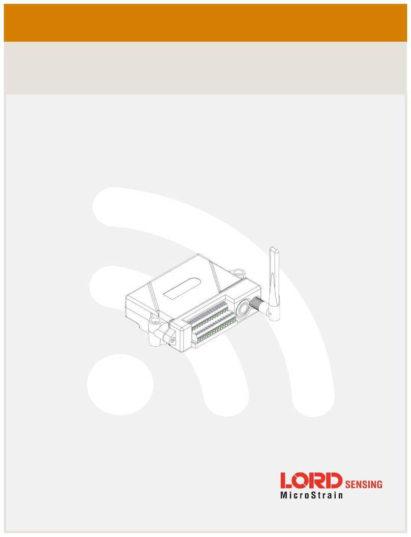
Lord MicroStrain WSDA-1500-LXRS User manual

LORD PRODUCTUSERMANUAL
WSDA®-1500-LXRS®
Wireless Sensor Data Aggregator

MicroStrain®Sensing Systems
459 Hurricane Lane
Suite 102
Williston, VT 05495
United States of America
Phone: 802-862-6629
Fax: 802-863-4093
http://www.microstrain.com
sensing_support@LORD.com
sensing_sales@LORD.com
Copyright © 2015 LORD Corporation
3DM®, 3DM-DH®, 3DM-DH3™, 3DM-GX1®, 3DM-GX2®, 3DM-GX3®, 3DM-GX4-15™, 3DM-GX4-25™, 3DM-GX4-45™,
3DM-GX4™, 3DM-RQ1™, 3DM-GQ4™, AIFP®, Ask Us How™, Bolt-Link®, DEMOD-DC®, DVRT®, DVRT-Link™, DEMOD-
DVRT®, EH-Link®, EmbedSense®, ENV-Link™, FAS-A®, G-Link®, G-Link2™, HS-Link®, IEPE-Link™, Inertia-Link®, Little
Sensors, Big Ideas.®, Live Connect™, LXRS®, MathEngine®, MicroStrain®, MVEH™, MXRS®, Node Commander®,
PVEH™, RHT-Link®, RTD-Link™, SensorCloud™, SG-Link®, Shock-Link™, Strain Wizard®, TC-Link®, Torque-Link™, V-
Link®, Watt-Link™, Wireless Simplicity, Hardwired Reliability™, and WSDA®are trademarks of LORD Corporation.
Document 8400-0048 Revision C
Subject to change without notice.

WSDA®-1500-LXRS®Wireless Sensor Data Aggregator User Manual
Table of Contents
1. Wireless Sensor Network Overview 7
2. Gateway Overview 8
2.1 GatewayComponents 9
2.2 GatewayInterface 10
3. System Operational Overview 11
3.1 Software Installation 11
3.2 System Connections 12
3.3 Gateway Operation 13
3.3.1 Gateway Configuration 13
3.3.2 Gateway Control Panel 15
3.4 Connecting to Node Commander® 17
3.5 Connect to Nodes 20
3.5.1 Adding a Node by Address 20
3.5.2 Using Node Discovery 21
3.6 Channel Configuration 22
3.7 Sampling Settings 24
3.8 Data Acquisition 25
3.9 Data Handling 30
3.9.1 Connecting to SensorCloud™ 31
3.9.2 Sensor Data Files 34
4. Gateway Communication 35
5. Gateway Configuration 36
5.1 Gateway Information 37
5.1.1 About the Gateway 38

WSDA®-1500-LXRS®Wireless Sensor Data Aggregator User Manual
5.1.2 Node List 40
5.2 Data Options Menu 41
5.2.1 CAN J1939 Output 42
5.2.2 SensorCloud™ Upload Filter 52
5.2.3 WSDA® Data Downloader Calibration Coefficients 53
5.2.4 Clear Stored Data 55
5.3 Gateway Tools Menu 55
5.3.1 Diagnostics 56
5.3.2 Configuration 57
5.3.3 Time Options 61
5.3.4 Reboot 63
5.3.5 OperatingSystem (OS) Upgrade 64
5.3.6 Change Password 65
5. Remote Connectivity 66
6. Using Node Commander® 69
6.1 Verify Gateway Communication 70
6.2 Gateway Communication Timeout 70
6.3 Removing a Gateway 71
6.4 Gateway Information 71
6.5 Transmit Power 72
6.6 Transmit Frequency 73
6.7 Monitor Mode 74
6.8 Network Broadcast 75
6.9 Node Configuration 76
6. Using the Beacon 77

WSDA®-1500-LXRS®Wireless Sensor Data Aggregator User Manual
6.10 System Bandwidth in Synchronized Sampling 77
6.11 Synchronized Sampling with Multiple Gateways 78
7. Data Processing 79
7.1 WSDA® Data Downloader 80
8. Gateway Installation 81
8.1 Installation Recommendations 81
8.2 Optimizing the Radio Link 82
8.2.1 Range Test 83
8.3 Multi-port Connector Interface 84
8.4 Gateway Power Supply 85
9. Troubleshooting 86
9.1 Troubleshooting Guide 86
9.2 Device Status Indicators 91
9.3 Communications Ports inWindows® 92
9.4 Technical Support 94
10. Maintenance 95
11. Parts and Configurations 96
11.1 Standard Models 96
11.2 Gateway Accessories 96
11.3 Recommended Sensors 97
11.4 Wireless System Equipment 98
11.5 Product Ordering 99
12. Specifications 100
12.1 Physical Specification 100
12.2 Operating Specifications 101

WSDA®-1500-LXRS®Wireless Sensor Data Aggregator User Manual
12.3 Radio Specifications 103
13. Safety Information 104
13.1 Power Supply 104
13.2 ESD Sensitivity 104
13.3 Disposal and Recycling 105
14. References 106
14.1 Reference Information 106
14.2 Glossary 107

WSDA®-1500-LXRS®Wireless Sensor Data Aggregator User Manual System Overview
7
1. Wireless Sensor Network Overview
The LORD MicroStrain ®Wireless Sensor Network is a high- speed, scalable, sensor data
acquisition and sensor networking system. Each system consists of wireless sensor interface
nodes, a data collection gateway, and full-featured user software platforms based on the LORD
MicroStrain®Lossless Extended Range Synchronized (LXRS®) data communications protocol.
Bidirectional wireless communication between the node and gateway enables sensor data
collection and configuration from up to two kilometers away. Gateways can be connected locally to
a host computer or remotely via local and mobile networks. Some gateways also feature analog
outputs for porting sensor data directly to standalone data acquisition equipment.
The selection of available nodes allows interface with many types of sensors, including
accelerometers, strain gauges, pressure transducers, load cells, torque and vibration sensors,
magnetometers, 4 to 20mA sensors, thermocouples, RTD sensors, soil moisture and humidity
sensors, inclinometers, and orientation and displacement sensors. Some nodes come with
integrated sensing devices such as accelerometers. System sampling capabilities are IEEE
802.15.4-compliant and include lossless synchronized sampling, continuous and periodic burst
sampling, and data logging. A single gateway can coordinate many nodes of any type, and multiple
gateways can be managed from one computer with the Node Commander®and SensorCloud™
software platforms. Integration to customer systems can be accomplished using OEM versions of
the sensor nodes and leveraging the LORD MicroStrain®data communications protocol.
Common wireless applications of LORD MicroStrain ®Sensing Systems are strain sensor
measurement, accelerometer platforms, vibration monitoring, energy monitoring, environmental
monitoring, and temperature monitoring.

WSDA®-1500-LXRS®Wireless Sensor Data Aggregator User Manual Gateway Overview
8
2. Gateway Overview
The WSDA®-1500-LXRS®Wireless Sensor Data Aggregator is a network gateway designed to
configure, co-ordinate, and collect sensor data from LORD MicroStrain®wireless sensor nodes.
The WSDA®-1500-LXRS®is Ethernet-capable and can be configured to operate with a static IP,
a DHCP-enabled LAN, or as a datalogger to local memory. Secure, web-based data access and
analysis is available with integration to the SensorCloud™ platform.
The WSDA®-1500-LXRS®is also capable of pushing sensor data onto a J1939-compatible CAN
bus either by sending all of the sensor messages to one CAN address or by broadcasting user-
selected messages onto the CAN bus.
Figure 1 - WSDA®-1500-LXRS®Wireless Sensor Data Aggregator

WSDA®-1500-LXRS®Wireless Sensor Data Aggregator User Manual Gateway Overview
9
2.1 GatewayComponents
The WSDA®-1500- LXRS®can be purchased individually or in a starter kit. The starter kit
includes everything required to operate the WSDA®-1500- LXRS®including a removable
external antenna, a power supply, and cables for interfacing with the host computer or network.
For a complete list of available configurations, accessories, additional system products, and
ordering information see Parts and Configurations on page 96.
Item Description Quantity
AWSDA®-1500-LXRS®Wireless Sensor Data Aggregator 1
BAntenna 1
CEthernet cable, 10 ft 1
DPower supply and plug adapter kit 1
-- Node Commander®Software Suite, User Manual, Quick Start
Guide, and WSDA®Access Certificate 1
Table 1 - Starter Kit Components

WSDA®-1500-LXRS®Wireless Sensor Data Aggregator User Manual Gateway Overview
10
2.2 GatewayInterface
The WSDA®-1500-LXRS®interfaces include a power input jack , a power on/off switch, an
antenna connector for attaching the gateway antenna, an Ethernet jack, a multi-use (multi-port)
connector, and a USB port reserved for future use.
The indicators on the WSDA ®- 1500- LXRS ®include a several device and data status
indicators, and a power indicator. The following table describes basic indicator behavior.For a
complete list of all indicator behaviors see Device Status Indicators on page 91.
Figure 2 - Ports and Indicators
Indicator Behavior Node Status
POWER OFF Gateway is off
ON green Gateway is on
CLOUD
Flashing blue Uploading data to SensorCloud™
ON green Web upload successful
ON red Web upload error
DATA Flashing green Receiving wireless data
Flashing blue Sync sampling beacon enabled
WSDA
ON green Fully booted & idle
Flashing blue & green Sampling and porting data through
Node Commander®
Table 2 - Basic Indicator Behaviors

WSDA®-1500-LXRS®Wireless Sensor Data Aggregator User Manual System Operational Overview
11
3. System Operational Overview
The gateway is the interface between LORD MicroStrain®sensor nodes and the data acquisition
computer or network. The gateway co-ordinates the configuration and sampling of the nodes and
can handle many nodes simultaneously. Communication between the nodes and gateway is
wireless and uses the LORD MicroStrain®LXRS®data communications protocol. LXRS®nodes,
and many legacy nodes, will communicate with any LXRS®gateway.
Communication protocols between the gateway and host computer vary depending on which
model gateway is used.Ethernet gateways have an embedded operating system and utilize a web
based interface for device configuration.
LORD MicroStrain®has two software programs available for data acquisition from the wireless
sensor network: SensorCloud™ and Node Commander®. SensorCloud™ is an optional web-
based data collection, visualization, analysis, and remote management platform based on cloud
computing technology. Node Commander®is used for configuring gateways and nodes, selecting
sampling modes and parameters, initializing data acquisition, and viewing and saving data.
The operational overview describes system hardware and software setup, and the basic
navigation of Node Commander®used to configure the node and begin data acquisition. A brief
overview of porting data to SensorCloud™ is also included. This section is included as a quick start
guide and is not a complete demonstration of all system and software capabilities.
3.1 Software Installation
To install Node Commander ®Software Suite on the host computer, run the installer
executable file and follow the on-screen prompts. The software is provided with all gateways
and is available on the LORD MicroStrain®website (see References on page 106).
The suite includes the following programs:
lNode Commander is used for configuring nodes and acquiring, viewing, and
saving data.
lLive Connect™is a TCP/IP-to-serial conversion tool that translates the
communications between Node Commander and an Ethernet gateway.
lWSDA®Data Downloader is used to download acquired data from the flash
memory card embedded in an applicable gateway, to a host computer.

WSDA®-1500-LXRS®Wireless Sensor Data Aggregator User Manual System Operational Overview
12
SensorCloud™ is an optional data collection, visualization, analysis, and remote
management tool. It is based on cloud computing technology and is accessed directly from a
web connection. For more information see Data Handling on page 30.
Users can also design custom programs with the open source data communications
protocol (see References on page 106).
3.2 System Connections
To acquire sensor data the following components are needed: a LORD MicroStrain®data
gateway and a local or networked host computer with access to the data acquisition software
(such as Node Commander®and SensorCloud™). For a connections overview refer to Figure
3 - System Connections .
The sensor, node, gateway, and software selection are application-dependent, but the basic
interfaces are the same. For a connections overview using the WSDA®-1500-LXRS®refer to
Figure 3 - System Connections .
Users can also write custom programs by utilizing the LORD MicroStrain®Wireless Sensors
Network Software Development Kit
Figure 3 - System Connections

WSDA®-1500-LXRS®Wireless Sensor Data Aggregator User Manual System Operational Overview
13
3.3 Gateway Operation
NOTE
The default configuration of Ethernet gateways is for DHCP network
connectivity. In order to change the gateway communication settings, initial
connection to a DHCP-enabled network is required.
The Ethernet gateway has three primary operating sequences:
a. Gateway configuration in the internal gateway operating system Control Panel
(accessible through Live Connect™and any non-deprecated web browser, or dir-
ectly through the browser)
b. Node configuration and data acquisition through Node Commander®
(accessible through Live Connect™)
c. Data acquisition, viewing, and analysis through SensorCloud™
(accessible through a live web connection)
3.3.1 Gateway Configuration
The WSDA ®- 1500- LXRS ®configuration Control Panel can be accessed using Live
Connect™or directly through a web browser.
To connect directly to the gateway Control Panel through a web browser, type the device's
IPaddress into the browser address bar and press enter (Figure 4 - Gateway Control Panel
Access (Browser)).
Figure 4 - Gateway Control Panel Access (Browser)

WSDA®-1500-LXRS®Wireless Sensor Data Aggregator User Manual System Operational Overview
14
To connect to the gateway Control Panel through Live Connect™, an initial connection to a
DHCP enabled network is required.
1. Connect the host computer and gateway to the DHCP network, and apply power to
the gateway. Verify the gateway status indicator shows that it is on and has
completed the boot up process (see GatewayInterface on page 10).
2. Open Live Connect™. The gateway will be detected automatically but, depending on
the network, it may take two to three minutes. Once detected, the gateway will appear
on the list of discovered devices and can be identified by its name or serial number
(with a WSDA®prefix) in the Device Name column (Figure 5 - Live Connect™
Interface).
Figure 5 - Live Connect™Interface
3. To access Control Panel through Live Connect™, highlight the device, and select
the View button (Figure 6 - Gateway Control Panel Access (Live Connect™ )).
Figure 6 - Gateway Control Panel Access (Live Connect™)

WSDA®-1500-LXRS®Wireless Sensor Data Aggregator User Manual System Operational Overview
15
3.3.2 Gateway Control Panel
Log in to the gateway Control Panel with the default credentials:
a. Login: wsda
b. Password: wsda
Figure 7 - Log-in to Control Panel
The default Control Panel page after log-in is the About page. This page provides general
information about the device including serial number, networkconnection type, and system
information, such as system time.
Figure 8 - Control Panel Main Menu

WSDA®-1500-LXRS®Wireless Sensor Data Aggregator User Manual System Operational Overview
16
There is a navigation panel on the left that contains three menu categories; General, Data,
and Tools (Figure 9 - Control Panel Menus).
Figure 9 - Control Panel Menus
a. General - This category includes menu selections for information about the gate-
way's identity and time settings (About) and the sensor nodes it currently has data
for in memory (Node List).
b. Data - This category includes menu selections that allow users to set which node
and channel data is uploaded to SensorCloud™ (Upload Filter), set which data is
pushed out the CAN J1939 port (J1939), apply calibration coefficients to data down-
loaded from the gateway internal memory (Calibration), and clear data from the
device internal memory (Clear Data).
c. Tools - This category includes menu selections for troubleshooting the gateway
(Diagnostics); configuring communication settings, enabling and disabling operating
sequences, changing the node synchronization beacon state, and changing the
gateway radio frequency (Configuration); configuring system time (Time Options);
rebooting the gateway (Reboot); updating the operating system (OS Upgrade); and
changing the Control Panel log-in (Change Password).

WSDA®-1500-LXRS®Wireless Sensor Data Aggregator User Manual System Operational Overview
17
3.4 Connecting to Node Commander®
Node configuration is done in Node Commander®. The following steps provide an overview
of how to access the sensor node configuration menus in Node Commander®through the
gateway Live Connect™interface. In these menus node sensing channels are configured
and enabled, sampling modes are selected, and data acquisition can be initiated. There are
many options for node configuration including setting the node to sample continuously,
sample periodically, and to start sampling on power up. This section provides an overview
on how to access the node menus and adjust basic settings. Refer to the node and the Node
Commander®user manuals for additional information (see References on page 106).
Configuration of the sensor nodes in Node Commander®is done through the gateway and
the Live Connect™interface, and must be done initially on a DHCPenabled network.
1. Connect the host computer and gateway to the DHCP network, and apply power to
the gateway. Verify the gateway status indicator shows that it is on and has
completed the boot-up process (see GatewayInterface on page 10).
2. Open the Live Connect™program. The gateway will be detected automatically but
depending on the network, it may take 2 to 3 minutes. Once detected, the gateway
will appear on the list of discovered devices and can be identified by its name or serial
number (with a WSDA prefix) in the Device Name column ( Figure 10 - Live
Connect™ Interface).
Figure 10 - Live Connect™Interface

WSDA®-1500-LXRS®Wireless Sensor Data Aggregator User Manual System Operational Overview
18
3. Highlight the device in Live Connect™, and select the Connect button (Figure 11 -
Connecting the Gateway to Node Commander®). This will enable access to the
Node Commander®software.
Figure 11 - Connecting the Gateway to Node Commander®
4. Once connected, a virtual serial port is assigned to the gateway and will appear in the
Port column (Figure 12 - Virtual Serial Port).
Figure 12 - Virtual Serial Port

WSDA®-1500-LXRS®Wireless Sensor Data Aggregator User Manual System Operational Overview
19
5. Open Node Commander®.
6. The gateway will appear automatically in the Controller window with a
communication port assignment.
Figure 13 - Ethernet Gateway Communication

WSDA®-1500-LXRS®Wireless Sensor Data Aggregator User Manual System Operational Overview
20
3.5 Connect to Nodes
Several methods can be used in Node Commander®to establish communication with the
nodes. This quick start section covers the two simplest methods; adding a node by address and
by using the node discovery feature.
3.5.1 Adding a Node by Address
Adding a node by address requires the node to be on the same communication frequency
as the gateway. The node address and frequency are indicated in the documentation
included with the node when it is purchased.
1. To add a node by address, right-click on the gateway name in the Controller window,
and select Add Node > Add Single Node (Figure 14 - Adding a Node by Address).
2. The node address and frequency are indicated in the documentation included with
the node. Enter the node address, and select OK. If the node is not found, a message
will appear and provide the option to scan for the node on other frequencies.
Alternately, the Node Discovery feature can be used.
Figure 14 - Adding a Node by Address
Table of contents
Other Lord MicroStrain Network Hardware manuals
Popular Network Hardware manuals by other brands

DIEBOLD NIXDORF
DIEBOLD NIXDORF RM4H Operator's manual

Etic Telecom
Etic Telecom XSRACK user guide

HighPoint
HighPoint NA381TB Quick installation guide

Hitachi
Hitachi SJ/L-EN Ethernet Communications Module instruction manual

Luxul
Luxul Xen XAP-1050 Quick install guide

Connected Inventions
Connected Inventions Ranger 1.1RCZ1 user manual

Bosch
Bosch wLSN System reference guide

TeleWell
TeleWell TW-EAV510 AC v2 Configuration guide

PairGain
PairGain HIGAIN HLU-232 manual

Fortinet
Fortinet FortiWiFi 20C-ADSL-A quick start guide

Adaptec
Adaptec LSM-FC2002 - Loop Resiliency And SES Module... installation guide

Dell
Dell PowerEdge M1000e Configuration guide