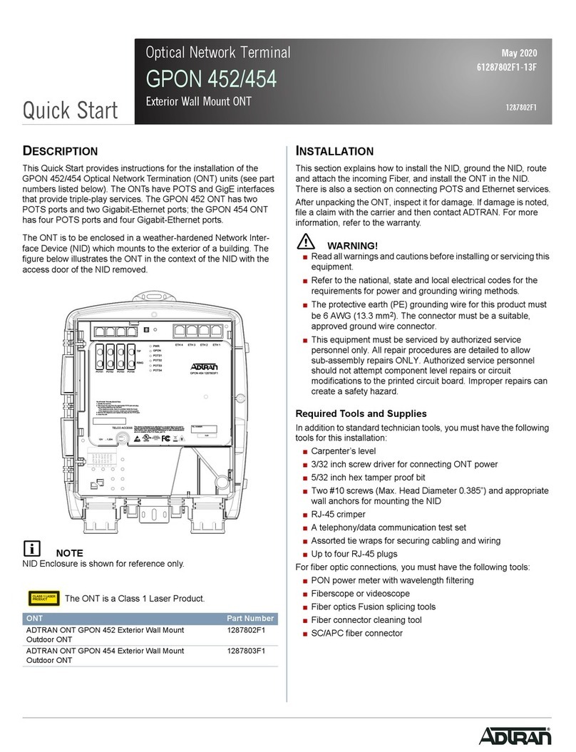
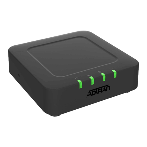
manuals.online logo
Brands
  1. Home
  2. •
  3. Brands
  4. •
  5. ADTRAN
  6. •
  7. Network Hardware
  8. •
  9. ADTRAN 414 RG User manual

ADTRAN 414 RG User manual

jobAid
1
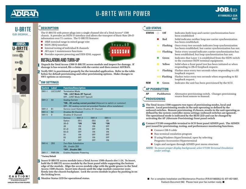
DESCRIPTION
This Job Aid supports the ADTRAN 414 RG 2 POTS/4 GigE ONT
Optical Network Termination (414 RG ONT). The illustration
above displays the rear of the 414 RG ONT and a cut-away of the
top depicting status LEDs.
Ports/Connectors
■Two POTS (PHONE) Ports
■Four Ethernet Ports
■12 VDC Power Plug
■UPS Connector
■WiFi Button
■Reset Button
■USB Port
Resetting the ONT
A reset button is available if the 414 RG ONT needs to be
rebooted. To reset the 414 RG ONT, press the RESET button for 5
seconds or longer.
WARNING
!
All settings will return to Factory Defaults: Registration
provisioning will be lost.
Voice Processing
Plain Old Telephone Service (POTS) uses in-band signaling tones
and currents to determine call status (for example, call request).
Because POTS allows for the transfer of audio signals below 3.3
kHz, POTS systems are also used for modems that allow data
transmission (referred to as dial up connections).
ADTRAN 414 RG
2 POTS/4 GigE ONT
with 2.4 GHz WiFi
Ethernet Interface
The 414 RG ONT supports data service through four 10/100/
1000Base-T Ethernet interfaces via RJ-45 connectors.
Power
Power is provided by a 12 VDC Power Adapter that is included
with the 414 RG ONT. The Power Adapter operates from a main
power source input of 100 to 240 VAC, 50/60 Hz, with a nominal
output of 12 VDC. The total power consumption with 4 Ethernet
Ports running and both POTS lines off-hook is approximately 15.0
Watts. A connection for an optional un-interruptible power
supply (UPS) is also provided.
UPS
The 414 RG ONT provides an optional connection for an Uninter-
ruptible power supply (UPS). An UPS is a battery backup system
designed to continue providing power when the primary power
source is lost. Power is supplied to the 414 RG ONT by a local
power source with battery backup that utilizes the AC power at
the customer premises that keeps the battery charged.
USB
There is a USB data connection on the rear of the 414RG ONT that
can be used for connection and communications with other
computers and electronic devices.
WiFi
The 414 RG ONT provides 802.11b/g/n compliant WiFi that support
2.4 GHz.
CLEI: BVMFF00A_ _ _
Product P/N: 1287790F1
Issue Date: May 2019
Document P/N: 61287790F1-22C
The following related online documents and resources provide additional information for this
product:
Total Access 5000 GPON OLT User Interface Guide
Total Access 5000 Series Fiber to the Premises Deployment Guide
ADTRAN 400 Series Residential Gateway ONT Basic Configuration Guide
RESET
USBGE 4GE 3GE 2GE 1PHONE 2 PHONE 1UPS12V
W
P
S
1234 21
WPS
2.4
WPS
Documentation for ADTRAN®Carrier Networks products is available for
viewing and download directly from the ADTRAN Support Community
website.
Go to: https://supportforums.adtran.com/welcome
Registration is required.
ADTRAN offers training courses on our products, including customized
training and courses taught at our facilities or at customer sites.
For inquiries, go to: http://adtran.com/training
261287790F1-22C
Step 1: Mounting
The 414 RG ONT can be placed on a desktop or mounted to a
wall.
Desk Top Installation
The 414 RG ONT can sit on a desktop. With a desk mount, ensure
the 414 RG ONT is not located in direct sunlight and is not located
next to any thermal obstructions.
Wall Mount Installation
NOTE
Refer to the Figure 1 when installing the 414 RG ONT on a wall
mount.
To wall mount the 414 RG ONT, refer to Figure 1 and complete
the following steps:
1. Decide on a location for the 414 RG ONT. Mount below eye-
level so the LEDs are visible.
Figure 1. Wall Mount Installation
2. Attach a 1/4 inch mounting board (typically plywood) to
the wall. If the wall is drywall construction, ensure the
mounting board is supported by the wall studs.
3. Install two #8 Pan Head screws (1 inch or greater in length)
using the key holes on the back of the 414 RG ONT as
location markers. Leave approximately 1/4 inch protruding
from the mounting surface.
4. Slide the 414 RG ONT over the Pan Head screws and exert a
small amount of downward pressure to ensure that the top
of the slots are resting on the shafts of the Pan Head screws.
Step 2: Connect Telephone
The 414 RG ONT has two telephone connections labeled
PHONE1 and PHONE2 on the rear of the 414 RG ONT. To
connect the primary telephone line, simply plug the cable running
from the primary telephone unit into the PHONE1 connection on
the rear of the 414 RG ONT. Any subsequent phones will be
connected to the PHONE2 jack.
Rear of SFU ONT
WPS
WiFi Protected Setup (WPS) is a feature used to connect to a WPS-
supported device. Pressing the WPS button enables the service.
To access this feature, refer to the documentation that accom-
panied your WiFi-supported device. The WPS information in the
LED Table on page 4 highlights the connection stages of this
feature.
INSTALLATION
After unpacking the 414 RG ONT, inspect it for damage. If
damage is noted, file a claim with the carrier and then contact
ADTRAN. For more information, refer to the warranty.
Installation Guidelines
The following are guidelines for this installation.
■Read all warnings and cautions before installing or servicing
the 414 RG ONT.
■Do no locate the 414 RG ONT in direct sunlight or next to any
thermal devices.
Installation Overview
To install the 414 RG ONT, you will need to complete the
following steps:
■“Step 1: Mounting”
■“Step 2: Connect Telephone”
■“Step 3: Connect Internet”
■“Step 4: Clean Fiber Optics Cable Connections”
■“Step 5: Connect Fiber Optics Cable”S
■“Step 6: Connect Power”
■“Step 7: Connect UPS”
Required tools
Standard technician tools and those listed below are required for
installing the 414 RG ONT:
■Carpenter’s level
■A telephony/data communication test set
■PON power meter with wavelength filtering
■Fiberscope or videoscope
■Two #8 Pan Head screws (1 inch or greater in length)
■Assorted tie wraps for securing cabling and wiring
For fiber optic connections, the following are required:
■Fiber optical fusion splice tools
■ODC Fiber cleaning tool
■SC Fiber connector
61287790F1-22C 3
Step 3: Connect Internet
The 414 RG ONT supports four 1 Gigabit (10/100/1000Base-T)
Internet connections labeled GE1 through GE4. To connect the
primary computer to the Internet, simply plug the Ethernet cable
running from the primary computer into the GE1 Ethernet
connection on the rear of the 414 RG ONT. Any subsequent
computers will be connected to the GE2 through GE4 ports.
Step 4: Clean Fiber Optics Cable Connections
WARNING
!
Do not look into the ends of optical fibers. Exposure to invisible
LASER radiation may cause serious retinal damage or even
blindness. Verify the optical source is disabled through the use of
an optical power meter before handling optical fibers.
Following is a list of suggestions for cleaning fiber optic connec-
tions:
■Always maintain dust caps and dust plugs installed when
connectors or adapters are not mated. Store spare dust caps in
a sealable plastic bag when not in use.
■Avoid allowing unmated connectors to touch surrounding
unrelated surfaces and do not touch a connector or bulkhead
ferrule for any reason other than while performing the
cleaning process.
■Use a fiberscope or videoscope to verify proper cleaning of
connectors prior to mating connecting components together.
■Use an appropriate quality fabric type cleaner and pure
alcohol (reagent grade, 99.5%pure) when cleaning the endface
of connectors. The alcohol can be applied with either
laboratory grade lint-free tissues or with pre-moistened
optical grade wipes.
■Do not use compressed air to clean optical connectors.
To clean the fiber connections, complete the following steps:
1. Remove any dust caps or connectors from bulkhead.
2. Insert a new fabric spiral wrapped cleaning tip into the
ferrule of the bulkhead.
3. Using your fingers, apply a firm pressure to the cleaner as
you twist the cleaner handle two or three times to create a
wiping action of the cleaning tip on the ferrule endface.
4. Discard the cleaning tip after using on a connectors.
Step 5: Connect Fiber Optics Cable
To connect the fiber optic cable, complete the following steps:
1. Remove the dust cover from the incoming fiber connector
and the dust cover on the fiber connection on the 414 RG
ONT.
2. Insert the incoming fiber connector in the fiber connection
port until you hear a “click”.
3. Rout the fiber optics cable so that it is free of sharp bends
and crimping.
Step 6: Connect Power
Plug the supplied 12V AC/DC Power Converter into the 12V
connection on the rear of the chassis. Connect the power plug to a
standard 120V AC outlet.
Using a UPS
The 414 RG ONT can typically use an un-interruptible power
supply (UPS) if desired. Power is supplied to the 414 RG ONT by
a local power source with battery backup that utilizes the AC
power at the customer premises. The UPS powers the 414 RG
ONT and functions as a battery backup (BBU) supplying
continuous 12 VDC. Refer to the installation material that is
provided with the UPS for installation details.
Step 7: Connect UPS
Connect the UPS to the 8-pin MOLEX connector labeled “UPS”
located on the rear of the SFU ONT chassis. Figure 2 represents
the MOLEX connector.
Figure 2. MOLEX Connector
The UPS Power/Alarm Connections Table, below, provides a
pinout of the connector.
NOTE
If an UPS is being used and the battery is disconnected or
becomes completely discharged, the 414 RG ONT is not protected
from power outages, and will send a “Battery Missing” alarm to
the OLT.
Pin-Out Description Alarm
1 Power Input (+12 VDC) -
2UPSStatus-OnBattery 1
3 UPS Status - Battery Missing 2
4 Signal Return -
5Power12VReturn -
6 UPS Status - Replace Battery 3
7 UPS Status - Low Battery 4
8 No Connection -
Warranty: ADTRAN will replace or repair this product within the warranty period if it does not
meet its published specifications or fails while in service. Warranty information can
be found online at www.adtran.com/warranty.
Trademarks: Brand names and product names included in this document are trademarks,
registered trademarks, or trade names of their respective holders.
Copyright © 2019 ADTRAN, Inc. All Rights Reserved. *61287790F1-22C*
LED STATUS
The LEDs are located beneath the plastic housing and are only
visible after power has been applied. The following table provides
the LED status during normal operations.
PROVISIONING
For complete provisioning information, refer to the ADTRAN 400
Series Residential Gateway ONT Basic Configuration Guide. This
guide provides basic provisioning information for 400 Series
Residential Gateway ONTs. You can also use the Total Access 5000
Label Status Indication
POWER 

Off
Green
AC or battery off
No Failure
FIBER 

2
Off
Green
Green Flashing
Fast
No connection to the OLT,
open fiber, failure at the ONT,
or power is Off
DS signal present and is within
operating range
Ranging in Progress
INTERNET 

Off
Green
No IP address configured on
WAN Interface, or Power is
Off
WAN Interface is configured
with IP address
GE 1-4 

2
Off
Green
Green Flashing
Fast
Link is down or not equipped
Link is up
Data is being sent or received
USB 

2
Off
Green
Green Flashing
Fast
Power Off or no device con-
nected
Device connected
Data is being sent or received
WIFI 

2
Off
Green
Green Flashing
Fast
Power is Off, or Wireless
2.4GHz is Disabled
Wireless 2.4GHz is Enabled
Data is being sent or received
on 2.4GHz
PHONE 1-2 

2
Off
Green
Green Flashing
Slow
Unequipped or on-hook and
not ringing
Line is off-hook
Line in ringing state
WPS 

2
Off
Green
Green Flashing
Fast
Power Off or WPS is Disabled
WPS is Enabled
WPS push button pressed and
device is ready to accept con-
nection
GPON OLT User Interface Guide. This guide provides all the infor-
mation necessary to provision the PON to which the 414 RG ONT
is connected.
SPECIFICATIONS
Refer to the following for a list of all specifications for the Indoor
414 RG ONT.
■Electrical
♦Voltage: 12.0 Volts typical
♦Minimum Voltage: 10.0 Volts
♦Maximum Voltage: 13.9 Volts
♦Power Consumption: Typical 18.0 watts
■Optical
♦TX min power: 0.5 dBm
♦TX max power: 5.0 dBm
♦RSSI max sensitivity: -27 dBm
♦RX overload: -8 dBm
♦TX wavelength: 1310 nm typical
♦RX wavelength: 1490 nm typical
■Physical
♦Height: 1.5 inches (3.81 centimeters)
♦Width: 8.5 inches(21.6 centimeters)
♦Depth: 7.0 inches(17.8 centimeters)
♦Weight: 1 pounds (0.45 kilograms)
■Environmental
♦Operational Temperature: 32°F to 104°F (0°C to 40°C)
♦Storage Temperature: –4°F to +122°F (–20°C to +50°C)
♦Relative Humidity: 90%, noncondensing
MAINTENANCE
The 414 RG ONT does not require routine hardware maintenance
for normal operation. ADTRAN does not recommend that repairs
be attempted in the field. Repair services may be obtained by
returning the defective unit to ADTRAN. Refer to the warranty
for further information. Field support for software is provided
through upgrade facilities.
SAFETY AND REGULATORY COMPLIANCE
Refer to the ADTRAN 414RG 2 POTS/4 GigE ONT Safety and
Regulatory Compliance Notice (P/N: 61287790F1-17) for detailed
safety and regulatory information.
Consultez l'avis sur la sécurité et la conformité à la réglemen-
tation pour ce produit (P/N: 61287790F1-17) pour obtenir des
renseignements détaillés sur la sécurité et la réglementation.
C A U T I O NC A U T I O N !
SUBJECT TO ELECTROSTATIC DAMAGE
OR DECREASE IN RELIABILITY.
HANDLING PRECAUTIONS REQUIRED.
ADTRAN CUSTOMER CARE:
From within the U.S. 1.800.726.8663
From outside the U.S. +1 256.963.8716
PRICING AND AVAILABILITY 1.800.827.0807

Other manuals for 414 RG

1

This manual suits for next models

1

Other ADTRAN Network Hardware manuals

ADTRAN NetVanta 6355 PoE User manual

ADTRAN

ADTRAN NetVanta 6355 PoE User manual

ADTRAN 602 User manual

ADTRAN

ADTRAN 602 User manual

ADTRAN HDSL4 Instruction Manual

ADTRAN

ADTRAN HDSL4 Instruction Manual

ADTRAN Total Access DSLAM 16-Port ADSL2+ Access Module... User manual

ADTRAN

ADTRAN Total Access DSLAM 16-Port ADSL2+ Access Module... User manual

ADTRAN Total Access 334 User manual

ADTRAN

ADTRAN Total Access 334 User manual

ADTRAN NetVanta 8044M User manual

ADTRAN

ADTRAN NetVanta 8044M User manual

ADTRAN NetVanta NetVanta ADSL NIM User manual

ADTRAN

ADTRAN NetVanta NetVanta ADSL NIM User manual

ADTRAN 1442823F1 User manual

ADTRAN

ADTRAN 1442823F1 User manual

ADTRAN T200 SHDSL User manual

ADTRAN

ADTRAN T200 SHDSL User manual

ADTRAN P/N 1204011L1 Service manual

ADTRAN

ADTRAN P/N 1204011L1 Service manual

ADTRAN 424 ONT User manual

ADTRAN

ADTRAN 424 ONT User manual

ADTRAN ISU 512E User manual

ADTRAN

ADTRAN ISU 512E User manual

ADTRAN FXS+ Dual User manual

ADTRAN

ADTRAN FXS+ Dual User manual

ADTRAN NetVanta 6360 User manual

ADTRAN

ADTRAN NetVanta 6360 User manual

ADTRAN HTU Nx64 User manual

ADTRAN

ADTRAN HTU Nx64 User manual

ADTRAN HD-10 BRI MUX Instruction Manual

ADTRAN

ADTRAN HD-10 BRI MUX Instruction Manual

ADTRAN Total Reach DDS-DP 5 Series Instruction Manual

ADTRAN

ADTRAN Total Reach DDS-DP 5 Series Instruction Manual

ADTRAN FXS/DPO/PLAR 1109403L2 Instruction Manual

ADTRAN

ADTRAN FXS/DPO/PLAR 1109403L2 Instruction Manual

ADTRAN Total Access 850 User guide

ADTRAN

ADTRAN Total Access 850 User guide

ADTRAN Total Access 300 Series Product manual

ADTRAN

ADTRAN Total Access 300 Series Product manual

ADTRAN TOTAL ACCESS 1200 User manual

ADTRAN

ADTRAN TOTAL ACCESS 1200 User manual

ADTRAN T200 IDSL OCU-R Instruction Manual

ADTRAN

ADTRAN T200 IDSL OCU-R Instruction Manual

ADTRAN Total Access 300 Series Product manual

ADTRAN

ADTRAN Total Access 300 Series Product manual

ADTRAN TSU ACE User manual

ADTRAN

ADTRAN TSU ACE User manual

Popular Network Hardware manuals by other brands

ICP DAS USA ZT-20 IOG Series quick start

ICP DAS USA

ICP DAS USA ZT-20 IOG Series quick start

Avocent MergePoint 5200 Specification sheet

Avocent

Avocent MergePoint 5200 Specification sheet

Russound BGB2 instruction manual

Russound

Russound BGB2 instruction manual

Siemens 2000592-001 user manual

Siemens

Siemens 2000592-001 user manual

TCAM TMAS TMN-10 user manual

TCAM

TCAM TMAS TMN-10 user manual

Concept Pro VHDIPL-V3 Series user manual

Concept Pro

Concept Pro VHDIPL-V3 Series user manual

Juniper SSR1300 Hardware guide

Juniper

Juniper SSR1300 Hardware guide

Matrix Switch Corporation MSC-HD88DES product manual

Matrix Switch Corporation

Matrix Switch Corporation MSC-HD88DES product manual

PMC-Sierra PM5354 Features

PMC-Sierra

PMC-Sierra PM5354 Features

Extreme Networks ExtremeCloud Appliance Series user guide

Extreme Networks

Extreme Networks ExtremeCloud Appliance Series user guide

Alcatel-Lucent vitalqip 5000 quick start guide

Alcatel-Lucent

Alcatel-Lucent vitalqip 5000 quick start guide

Vista Viper quick start guide

Vista

Vista Viper quick start guide

Tektronix 7B87 instruction manual

Tektronix

Tektronix 7B87 instruction manual

Tyco EV 4UA Hybrid Series quick start guide

Tyco

Tyco EV 4UA Hybrid Series quick start guide

Showgear RCA-FSM-18 user manual

Showgear

Showgear RCA-FSM-18 user manual

AvaLAN AW5802mTR-EVAL user manual

AvaLAN

AvaLAN AW5802mTR-EVAL user manual

Panasonic Transistors 2SC4805G Specifications

Panasonic

Panasonic Transistors 2SC4805G Specifications

Patton electronics 2500RC user manual

Patton electronics

Patton electronics 2500RC user manual

manuals.online logo
manuals.online logoBrands
  • About & Mission
  • Contact us
  • Privacy Policy
  • Terms and Conditions

Copyright 2025 Manuals.Online. All Rights Reserved.