manuals.online logo
Brands
  1. Home
  2. •
  3. Brands
  4. •
  5. Loreme
  6. •
  7. Measuring Instrument
  8. •
  9. Loreme IPL 144V User manual

Loreme IPL 144V User manual

E 1
Programmable electrical network analyser
LOREME 12, rue des Potiers d'Etain Actipole BORNY - B.P. 35014 - 57071 METZ CEDEX 3
Phone 03.87.76.32.51
Contact : Commercial@Loreme.fr - Techniqu[email protected]
Download manual at : www.loreme.fr
REV 0.2 - 28/04/14
CONFIGURATION HANDBOOK
IPL 144V
E 2LOREME 12, rue des Potiers d'Etain - 57071 Metz 03.87.76.32.51 - Email: Comm[email protected] - Techniqu[email protected]
Table of contents
RS232 LINK SETTING ............................................................................................................................................. p3
DEVICE PRESENTATION ......................................................................................................................................... p4
USER INTERFACE .......................................................................................................................................... p4
CONFIGURATION ..................................................................................................................................................... p6
1) Visualization ............................................................................................................................................... p6
2) Method ........................................................................................................................................................ p6
3) Language ................................................................................................................................................... p7
4) Network ...................................................................................................................................................... p7
5) Energy ........................................................................................................................................................ p7
6) Relays ........................................................................................................................................................ p7
7) Communication ......................................................................................................................................... p8
WIRING FUNCTION ................................................................................................................................................. p9
DIAGRAM OF CONNECTIONS ................................................................................................................................ p12
PROFIBUS CONNECTION ....................................................................................................................................... p14
RS485 Modbus ......................................................................................................................................................... p15
RS485 Profibus ........................................................................................................................................................ p24
EMC CONSIDERATION ........................................................................................................................................... p28
TABLE OF CONTENTS
E 3
RS232 link setting
Enter name for the new
connection
Start a "hyper Terminal" connection :
- Click on "START" button
Up to XP version
- Go to "Programs \ Accessories \ Communication \ Hyper Terminal"
- Click on "Hypertrm.exe"
Or if the software was downloaded
- Go to "All programs \ HyperTerminal Private Edition"
- Click on "HyperTerminal Private Edition"
Choose:
- 9600 bauds
- 8 DATA bits
- no parity
- 1 stop bit
- XON/XOFF
The device can be configured or updated in terminal mode via an RS232 link.
Step 1: Driver installation for USB / RS232 adapter
- download driver at www.loreme.fr:
http://www.loreme.fr/aff_produits.asp?rubid=53&langue=fr
- Click on executable file to install the driver,
- Plug the cable on a USB port, Windows install a new serial communication port COMx
(x >= 4).
Note :
The use of the cable on another USB port don’t generates a new communication port.
Use of another adapter generates another communication port number (COMx) and re-
quires the reconfiguration of the hyperterminal.
The terminal emulation software for PC « HyperTerminal » is resident in windows up to XP version. For later ver-
sions, it is downloadable on : www.loreme.fr in download part ( http://www.loreme.fr/HyperTerm/htpe63.exe )
=> Run the downloaded software to install it.
1
Step 2: Setting of terminal emulation software (PC with windows).
2
345
Choose the communication port
related to the adapter.
The PC is now in terminal mode, connect it to the device by plugging the RS232 cable. The measure is now dis-
played on the terminal. To access configuration, press ’C’ key.
6
7
Note: To modify the parameters of terminal session whereas this one is connected, it is necessary to disconnect it, mod-
ify the parameters and then to reconnect it.
When leaving Hyper terminal, the following window will
appear. By saving, the terminal
session will start with the same
configuration. Thus, the shortcut will permit to communi-
cate with all LOREME devices.
TABLE OF CONTENTS
E 4LOREME 12, rue des Potiers d'Etain - 57071 Metz 03.87.76.32.51 - Email: Comm[email protected] - Techniqu[email protected]
Device Presentation
The purpose of this configuration handbook is to allow to become familiar with functions supplied by the device.
The device provides functions required to the analysis of every networks. It possess 3 voltage inputs and 3 current in-
puts isolated allowing to realise direct and alternating measures, one-phase or three-phase, balanced or unbalanced,
with or without neutral.
It's necessary to notice the differences between different available models:
.IPL144V: basic version.
.IPL144V/R: 2 configurable relays in alarm or meter option.
.IPL144V/CM: 1 MODBUS/JBUS RS485 link option.
.IPL144V/CP: 1 PROFIBUS link option.
The technical data sheets are downloadable here: http://www.loreme.fr/fichtech/CPL35_eng.pdf
USER INTERFACE
- 3 push-buttons:
"Al config" allows to access to alarm threshold adjustment (subsequently available),
"Up" allows to select displayed measure type for zone A,
"Down" allows to select displayed measure type for zone B.
A simultaneously press on "Up" and "Down" keys allows to reset all energies measures if the function is validated
in RS232 configuration.
Each zone disposes of 6 display modes:
For zone A, display possibilities are the next:
- Star voltage phase 1, 2, 3 ("U" leds are on),
- Currents phase 1, 2, 3 ("I" leds are on),
- Frequency, Cos Phi and network type, ("F", "Cos" and "L/C" leds are on),
- Actives powers phase 1, 2, 3 ("P" leds are on),
- Reactive powers phase 1, 2, 3 ("Q" leds are on),
- Interlinked voltage phase 12, 23, 31 ("U12", "U23" and "U31" leds are on),
LED Display
Push buttons
The IPL144V front side is composed of :
- 3 displays of 3 digits, 1000 points (zone A)
- 1 display of 4 digits, 10000 points (zone B)
- 2 reds leds indicating alarms state,
- 8 reds leds indicating scale factor for each displayed
value
- 22 reds leds indicating display value type
TABLE OF CONTENTS
E 5
For zone B, display possibilities are the next:
- Network active power, ("P" led is on)
- Network reactive power, ("Q" led is on),
- Network consumed active energy, ("W" led and "P" led are on),
- Network inductive reactive energy, ("W" led and "Q" led are on),
- Network generated active energy, ("W" led, "P" led and "+/-" led are on),
- Network capacitive reactive energy, ("W" led, "Q" led and "+/-" led are on)
Measures are given in Kilo when "K" led is on, Mega when "M" led is on, Giga when "K" and "M" leds are on.
TABLE OF CONTENTS
E 6LOREME 12, rue des Potiers d'Etain - 57071 Metz 03.87.76.32.51 - Email: Comm[email protected] - Techniqu[email protected]
Configuration
1) Visualization:
When switching on, device is automatically put in measure mode.2 displays modes are available:
2 lines mode: one only measure visualization,
Full-screen mode: all measures visualization.
This access keyboard keys allow to modify visualization mode on RS232:
"1" phase 1, "Space" measure type change,
"2" phase 2, "$" full-screen (PC only),
"3" phase 3, "Enter" 2 lines mode return,
"S" network (3L). "C" configuration access,
On 2 lines display mode, the visualization is the next:
STAR VOLTAGE L1 Measure type and phase displayed
230 V Measure value
On full screen display mode, the visualization is the next:
L1 L2 L3 3L
VOLTAGE 230 V 229 V 225 V 228 V
398 V 392 V 392 V 394 V
CURRENT 1.13 A 1.23 A 1.24 A 1.21 A
FREQUENCY 50 Hz 50 Hz 50 Hz 50 Hz
COS PHI 0.99 0.99 0.99 0.99
ACTIVE P. 260 W 287 W 279 W 829 W
REACTIVE P. 14 var 15 var 17 var 46 var
APPARENT P. 259 VA 287 VA 279 VA 829 VA
ACTIVE CONS. W. 54 kW.h 47 kW.h 49 kW.h 150 kW.h
ACTIVE GENE. W. 0 kW.h 0 kW.h 0 kW.h 0 kW.h
REACTIVE IND. W. 0 kvar.h 0 kvar.h 0 kvar.h 0 kvar.h
REACTIVE CAP. W. 5 kvar.h 4 kvar.h 4 kvar.h 13 kvar.h
UNBALANCED TRIPHASE NETWORK WITH NEUTRAL
CT RATIO 1.00
TI RATIO 1.00
For a better visualization of full-screen mode on PC, it is advised to use KERMIT software. This utilisation mode
slows down the device, It is recommended to quit this mode when it is not necessary.
2) Method:
This manual recapitulates different possibilities of configuration: language, network, energy, relay 1, relay 2, communica-
tion. To enter in configuration mode, type on "C" key.
2.1) Menu selection:
Example: INPUT
Y - N
The choice is done by typing on "Y" or "N" keys. This choice allows access to different configuration menus.
2.2) Parameter selection:
Example: VOLTAGE or VOLTAGE
(Y-N) YES (Y-N) NO
Previous choice = YES: - push on "Y" => Validation, choice = YES,
- push on "Enter" => Validation, choice = YES,
- push on "N" => Change, choice = NO.
Previous choice = NO: - push on "N" => Validation, choice = NO,
- push on "Enter" => Validation, choice = NO,
- push on "Y" => Change, choice = YES.
Choices are made pushing on "Y" or "N" keys, and validation by pushing on "Enter" (PC) / "EXE" (PSION) when the
answer "Y" or "N" is displayed. Pushing on the key "Enter" / "EXE" without modification allows to validate previous
answer.
TABLE OF CONTENTS
E 7
2.3) Value acquisition:
Example: LOW SCALE
4 mA
Two possibilities: - The validation without modification by pushing on "Enter" / "EXE",
- The keyboard value modification (simultaneous display), then the validation by "Enter" / "EXE".
Note concerning the value acquisition:
- It is possible, when a mistake is made during a value acquisition, before validating it, to go back by pressing the "DEL"
key (only on PSION), which re-displays the message without taking notice of the wrong value.
- In configuration mode, if there's no action during 2 minutes, device goes back in operating mode without taking notice
of the modifications made before.- In configuration mode, if you want to shift to measure mode without taking notice of
modifications made before, you just have to press "ESC" (PC) or "SHIFT + DEL" (PSION) key.
In configuration, if channels/phases sum is chosen, device calculates:
- channels mean for voltages, currents and frequency.
- channels sum for powers and energies.
- network result for cos phi (power factor)
3) Language:
Languages possibilities are French or English.
4) Network:
The possibilities of wiring on network are: - in AC: - one-phase,
- balanced three-phase without neutral,
- balanced three-phase with neutral,
- unbalanced three-phase without neutral,
- unbalanced three-phase with neutral.
- in DC: - 1 channel,
- 2 channels,
- 3 channels.
It is also necessary to configure ratio transformer if inputs are not directly wired on network:
- PT ratio, potential transformer,
- CT ratio, current transformer.
Ex: Intensity transformer with 100 A primary and 5 A secondary.
Transformer ratio setting = primary / secondary = 20.
5) Energy:
This menu gets the possibility to:
- validate the access to the energies reset with push-buttons on device's front side (display option),
- reset all the energies.
Warning: All the energies are definitely reset.
6) Relays 1 and 2:
Each of the two relays has the same possibilities of configuration.
The relay can be use in two modes : alarm or energy meter.
6.1) Alarm:
The relays configuration in alarm is composed of 2 rubrics:
- measures parameters:
measured value:
- star voltage or interlinked voltage (according to network type),
- current,
- frequency,
- cos phi,
- active, reactive, apparent power
- active consumed or generated energy,
- reactive inductive or capacitive energy.
TABLE OF CONTENTS
E 8LOREME 12, rue des Potiers d'Etain - 57071 Metz 03.87.76.32.51 - Email: Comm[email protected] - Techniqu[email protected]
measured phase or channel according to network configuration:
- phase or channel 1,
- phase or channel 2,
- phase or channel 3,
- phases or channels sum or mean.
- alarm parameters:
detection type, high threshold or low threshold,
threshold,
hysteresis.
The alarm works in this way:
- High threshold detection: .alarm is activated when measure goes beyond threshold,
.alarm is removed when measure goes below threshold less hysteresis.
- Low threshold detection: .alarm is activated when measure goes below threshold,
.alarm is removed when measure goes beyond threshold more hysteresis.
6.2) Energy meter:
The relays configuration in meter is composed of 2 rubrics:
- measures parameters:
measured value:
- consumed or generated active energy,
- inductive or capacitive reactive energy,
measured phase or channel according to network configuration:
- phase or channel 1,
- phase or channel 2,
- phase or channel 3,
- phases or channels sum.
- meter parameter:
impulse load value (kW.h or kvar.h).
7) Communication:
7.1) MODBUS:
The communication configuration is composed of 3 rubrics:
- device address in communication network (1 to 255),
- speed (1200, 2400, 4800, 9600, 19200, 38400 bauds),
- parity (even, odd, without).
7.2) PROFIBUS:
The communication configuration is composed of 2 rubrics:
- device address in communication network (0 to 126),
- speed (9600, 19200, 93.75K, 187.5K, 0.5M, 1.5Mbauds)
The data exchange are the measure in 32b integer and the command for reset the energy.
It is necessary to also configure the data format which will be used in the communication:
- data in "NORMAL" mode : 32 bits integer, MSB send first.
- data in "SPECIAL" mode : 32 bits integer, LSB send first.
For more details, see RS485 communication Modbus or Profibus chapter at the end of handbook.
TABLE OF CONTENTS
E 9
Function is only used for a balanced or unbalanced three-phase with or without neutral network. It allows a wiring
adaptation at device operating mode. It is so possible to permute voltage and current by a simple intervention on key-
board by way of RS232 link. Three keys are used, "+" to permute phase order, "-" to reverse current direction, "Enter" to
validate wiring.
1) Balanced three-phase:
1.1) Operating mode:
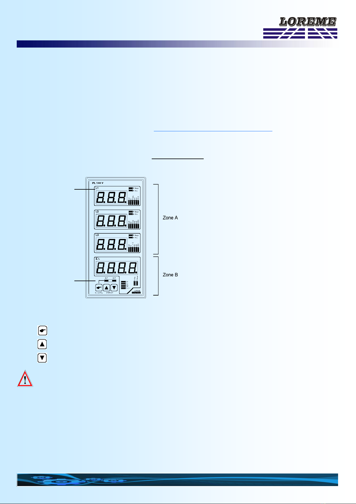
In this operating mode, device use only one voltage and one current (L1 and I1 input, see diagrams of connection). It
measures voltage, current and frequency, calculates powers, cos phi, energies of measured phase and, according to the
network configuration, with or without neutral, determinates finals results of the network (3L).
The device allows to adapt itself to an existing wiring or to a bad identification of voltages and currents, that is to say that
it can use L1, L2 or L3 voltage with I1, I2 or I3 current for a wiring with neutral or L12, L23 or L31 voltage with I1, I2 or I3
current for a wiring without neutral.
1.2) Method:
The function is realized by the way of RS232 link. It's by a "Cos Phi" value visualization that user will be able to determi-
nate if wiring is correct or if it must be modify.
To do that, it's necessary to be in 2 lines mode and to select "Cos Phi" measure ("Space" key).
The function start is realized by "+" or "-" keyboard keys.
At this moment, a message indicates operating mode:
WIRING 1 Wiring message, wiring type
-0.51 Example of incorrect "Cos Phi" value
"1" specifies wiring number
The "+" key allows to modify wiring with insertion of a phase between voltage and current.
The "-" key allows to reverse current direction if there is phase opposition, negative Cos Phi value.
When Cos Phi value becomes coherent according to installation, we obtain the next transmission:
WIRING -X Wiring message, wiring type
0.90 Example of correct "Cos Phi" value
"-" reverses current, "X" specifies wiring number
At this moment, you just have to validate selected wiring by "Enter" key.
This one is stored and remain active even after a power off.
In the balanced three-phase mode, it exists 3 different wiring types. So, in few seconds and without intervention on con-
nection, device adapt itself completely to network.
2) Unbalanced three-phase without neutral:
2.1) Operating mode:
n this operating mode, device uses two voltages and two currents (L1, L2 and I1, I2 inputs, see diagrams of connection).
It measures voltage, current and frequency, calculates powers, cos phi, energies of each of the two phases and determi-
nates finals results of the network (3L).
The device allows to adapt itself to a bad identification of U/I couple of each phase. For instance, by default, device as-
sociates L1 input voltage, that's to say L13, with I1 input current and L2 input voltage, that's to say L23, with I2 input cur-
rent. The wiring function allows to choose current/voltage association. So, it is possible to use L13 and L23 with I1 and
I2, L12 and L32 with I1 and I3 or L21 and L31 with I2 and I3. More, measure couples order will be able to be permuted.
The single obligation of wiring is the use of voltage phase in which no current is measured as reference phase. It must
be wired on voltage measure ground terminal. (L3 and N, see diagrams of connection).
Whenever, a verification will be realized to inform user of a double use of a current or a voltage, or a no conformity wir-
ing.
2.2) Method:
The function is realized by the way of the RS232 link. It's by a "Cos Phi" value visualization on phases 1 and 2 that user
will be able to determinate if wiring is correct or if it must be modify.
Wiring Function
(Function reserved for experienced users)
TABLE OF CONTENTS
E 10 LOREME 12, rue des Potiers d'Etain - 57071 Metz 03.87.76.32.51 - Email: Commercial@Loreme.fr - Technique@Loreme.fr
To do that, it is necessary to be in 2 lines mode and to select "Cos Phi" measure ("Space" key). For correct each phase,
it is essential to visualize phase that must be corrected (key "1" for phase "1", key "2" for phase "2").
The function start is realized by "+" or "-" keyboard keys.
At this moment, a message indicates operating mode:
WIRING L1 1/1 Wiring message, corrected phase, wiring type
-0.51 Example of incorrect "Cos Phi" value
1/1 associates L1 with I1
The "+" key allows to modify wiring by specify current (I1 or I2) associated to voltage (L1 or L2).
The "-" key allows to reverse current direction if there is phase opposition, negative Cos Phi value.
When Cos Phi value becomes coherent according to installation, we obtain the next transmission:
WIRING L1 -X/Y Wiring message, corrected phase, wiring type
0.90 Example of correct "Cos Phi" value
"-" reverses current, "X/Y" associates LX with IY
At this moment, you just have to validate the selected wiring by "Enter" key.
This one is stored and remain active even after a power off.
The procedure is the same for phase 1 and 2.
If the message "WIRING NO CONFORMITY" displays, It must take account only after 2 measured phases correction.
Whenever, if this message displays after complete correction of network, it does mean that a current or a voltage has
been used twice and that chosen wiring is incorrect. It is so necessary to modify wiring by simply changing reference
phase voltage (wired-up in L3-N).
In this unbalanced three-phase without neutral operating mode, it exists for each phase 4 different wiring types. So, in
few seconds and with a tiny intervention on voltage connection, device adapt itself completely to network.
Possible wiring: Phase L1 voltage 1 with current 1
voltage 1 with current 2
voltage 2 with current 1
voltage 2 with current 2
Phase L2 voltage 1 with current 1
voltage 1 with current 2
voltage 2 with current 1
voltage 2 with current 2
3) Unbalanced three-phase with neutral:
3.1) Operating mode:
In this operating mode, device uses the three voltages and the three currents (L1, L2, L3 and I1, I2, I3 inputs, see dia-
grams of connection). It measures voltage, current and frequency, calculates powers, cos phi, energies for each of the
three phases and determinates finals results of the network (3L).
The device allows to adapt itself to a bad identification of U/I couple of each phase. For instance, by default, device as-
sociates L1 input voltage with I1 input current, and the same for each phase. The wiring function allows to choose cur-
rent/voltage association, that's to say that L1, L2 and L3 will be able to be associated with I1, I2 or I3 in the desire order.
Whenever, a verification will be realized to inform user of a double use of a current, wiring no conformity.
3.2) Method:
The function is realized by the way of RS232 link. It's by a "Cos Phi" value visualization on phases 1, 2 and 3 that user
will be able to determinate if wiring is correct or if it must be modify.
To do that, it is necessary to be in 2 lines mode and to select "Cos Phi" measure ("Space" key). For correct each phase,
it is essential to visualize phase that must be corrected (key "1" for phase "1", key "2" for phase "2", key "3" for phase
"3").
The function start is realized by "+" or "-" keyboard keys.
At this moment, a message indicates the functioning mode:
WIRING L1 1/1 Wiring message, corrected phase, wiring type
-0.51 Example of incorrect "Cos Phi" value
1/1 associates L1 with I1
TABLE OF CONTENTS
E 11
The "+" key allows to modify wiring by specify the current (I1, I2 or I3) associated to corrected phase voltage. The "-" key
allows to reverse current direction if there is phase opposition, negative Cos Phi value.
When Cos Phi value becomes coherent according to installation, we obtain the next transmission:
WIRING L1 -1/X Wiring message, corrected phase, wiring type
0.90 Example of correct "Cos-Phi" value
"-" reverses current, "1/X" associates L1 with IX
At this moment, you just have to validate the selected wiring by "Enter" key.
This one is stored and remain active even after a power off.
The procedure is the same for phase 1, 2 and 3.
If the message "WIRING NO CONFORMITY" displays, It must take account only after 3 measured phases correction.
Whenever, if this message displays after complete correction of network, it does mean that a current has been used
twice and that chosen wiring is incorrect.
In the unbalanced three-phase with neutral operating mode, it exists for each phase 3 different wiring types. So, in few
seconds and without intervention on connection, device adapts itself completely to network.
Possible wiring: Phase L1 voltage 1 with current 1
voltage 1 with current 2
voltage 1 with current 3
Phase L2 voltage 2 with current 1
voltage 2 with current 2
voltage 2 with current 3
Phase L3 voltage 3 with current 1
voltage 3 with current 2
voltage 3 with current 3
TABLE OF CONTENTS
E 12 LOREME 12, rue des Potiers d'Etain - 57071 Metz 03.87.76.32.51 - Email: Commercial@Loreme.fr - Technique@Loreme.fr
PC - ANALYZER LINK
DIAGRAMS OF CONNECTIONS
Single phase
Three phase balanced with neutral
default wiring with L1 / i1
For other use of voltage or current, the "wiring function" may be
used to adapt the device to network
TABLE OF CONTENTS
E 13
Diagram of connection
Three phase balanced without neutral
default wiring with L12 / i1
For other use of voltage or current, The "wiring function" may be used to
adapt the device to network
Three phase unbalanced without neutral
default wiring with L13 / i1 and L23/ i2
For other use of voltage / current couple, the "wiring function" may be
used to adapt the device to network. Ensure that voltage use as
reference is the phase (L3 - N) with no current measurement.
Diagram of connection
Three phase unbalanced with neutral
default wiring with L1 / i1, L2 / i2 and L3 / i3
For other use of voltage / current couple, the "wiring function" may be
used to adapt the device.
Three phase unbalanced without neutral and 3 currents
default wiring with L1 / i1, L2 / i2 and L3 / i3
Setting in "tree phase , unbalanced, with neutral" the 3x 0V are internally
linked, the device reconstruct a pseudo neutral.
For other use of voltage / current couple, the "wiring function" may be used
to adapt the device.
TABLE OF CONTENTS
E 14 LOREME 12, rue des Potiers d'Etain - 57071 Metz 03.87.76.32.51 - Email: Commercial@Loreme.fr - Technique@Loreme.fr
Profibus connection
TABLE OF CONTENTS
E 15
RS485 Modbus
1) Internal structure:
1.1) Presentation:
The device is divided in two cells. Each cell has a specific function while keeping a continuous exchange of pieces of
information with the second cell. The first cell is in charge of the measure, analysis and conversion function.
The second cell is in charge of the communication function. The information exchange is continuous and automatic.
1.2) Measure function:
The measure cell runs the acquisition of the different signals and calculates all the values with regards to the configura-
tion of the device.
It also runs all the output functions (analogical, alarm, meter, RS 232). All measured or calculated parameters are stored
in the system memory and are constantly refreshed.
1.3) Communication function:
The communication cell runs the RS485 communication interface in the MODBUS/JBUS protocol. It analyzes the re-
quests of the main station and answers if the device is addessed. It draws all these data from the system memory that
can be continuously accessed.
1.4) System memory:
Each cell can continuously access the system memory. The latter has a dual access, which allows a reading/writing of
the data whitout any possible internal conflicts.
2) Communication:
The type of protocol used is: MODBUS/JBUS in RTU mode. The communication has neither header nor delimitator of
frame. The detection of the start of frame is made by a silence whose time is at least equal to the transmission of 3.5
bytes. It implies that a frame received can be processed only after a time equal to the silence given before. The time of
this silence is directly linked to the speed of transmission of the system:
Ex: Speed 9600 bauds - no parity (10 bits/byte)
Silence = (3.5 x 10) / 9600 = 3.64 ms
The device starts to process the frame 3.64 ms after receiving the last byte.
The time separating two bytes from a same frame must be inferior to a silence. If the user does not comply with this con-
dition, the second byte will be considered as the first one of a new frame.
The interval of time separating the end of reception of the last byte of the question frame and the end of emission of the
first byte of the answer frame (detection of frame of the main station) constitutes the answer time of the device.
This answer time Trep includes:
- the silence (time of 3.5 bytes) Ts,
- the processing of the frame Tt,
- the emission of the first byte Te1.
TABLE OF CONTENTS
E 16 LOREME 12, rue des Potiers d'Etain - 57071 Metz 03.87.76.32.51 - Email: Commercial@Loreme.fr - Technique@Loreme.fr
The time beyond which the device does not answer is called "TIME OUT". It depends on the transmission parameters
(speed, format) and the type of the function asked (reading, writing). This time must be defined by the user and must be
superior to the answer time of the device.
A complete communication cycle includes : - the question frame transmission Tq
- the device answer time Trep
- the answer frame transmission Tr
Three reasons might cause a TIME OUT: - wrong transmission data at the question frame time
- wrong configuration of the TIME OUT on the main station
- dependent station out-of-order.
3) Implementation:
3.1) Parameter:
Before starting up the RS485 MODBUS/JBUS communication, make sure that:
- the transmission speed is identical between the slaves (LOREME devices) and the main station.
- the parity is identical between the slaves (LOREME devices) and the main station.
- the addresses are correctly distributed among the stations (LOREME devices),
- the TIME OUT is correctly adjusted on the main station.
All the speed parameters , parity and address must be configured on the devices with the RS232 link.
The devices .configuration possibilities are the following ones:
- address: from 1 to 255
- speed: 600, 1200, 2400, 4800, 9600, 19200, 38400 bauds
- parity: even, odd, without.
- Data format
3.2) Interconnection:
The RS485 interface used allows to connect 128 dependent stations on the same network. For better operating condi-
tions (noise immunity), the network will have to be made up of a twisted pair.
4) Communication time:
4.1) Procedure:
Analysis of the times of communication for parameters of data transmission and for particular cases.
- reading measure phase, energy,
- energy reset,
- speed: 9600 bauds, parity: none.
4.2) Voltages reading:
Reading of 6 words (12 bytes) from address $A002 to $A007 (phase 1, 2, 3)
- 8 bytes question frame
Tq = (8 x 10) / 9600 = 8.33 ms
- Silence Ts = (3.5 x 10) / 9600 = 3.64 ms
- Processing Tt = 6 ms
- Emission 1st byte
Te1 = (1 x 10) / 9600 = 1.04 ms
- Answer time
Trep = Ts + Tt + Te1 = 10.68 ms
- Answer frame (17 bytes)
Tr = [(17 - 1) x 10] / 9600 = 16.66 ms
- Complete cycle
Tcyc = Tq + Trep + Tr = 35.65 ms
TABLE OF CONTENTS
E 17
Note:
The processing time Tt is fixed. It depends neither on the speed nor on the transmission format. Consequently, for new
transmission parameters, all the times are going to change but for Tt. To set the TIME OUT of the system, you just have
to calculate the answer time Trep of the dependent station according to the parameters of communication.
For a total phase reading, the time of cycle of the system is about 36 ms.
4.3) Energies reading:
Reading of 8 words, 16 bytes, of the address $A01E to $A025 (active consumed and generated, and reactive inductive
and capacitive energies)
- 8 bytes question frame Tq = (8 x 10) / 9600 = 8.33 ms
- Silence Ts = (3.5 x 10) / 9600 = 3.64 ms
- Processing Tt = 6 ms
- Emission 1st byte Te1 = (1 x 10) / 9600 = 1.04 ms
- Answer time Trep = Ts + Tt + Te1 = 10.68 ms
- Answer frame (37 bytes) Tr = [(21 - 1) x 10] / 9600 = 20.83 ms
- Complete cycle Tcyc = Tq + Trep + Tr = 39.84 ms
4.4) Energies reset:
Reset of the active consumed and generated, and reactive inductive and capacitive energies by the writing of word
$55AA at the address $7000.
- question frame Tq = (8 x 10) / 9600 = 8.33 ms
- silence Ts = (3.5 x 10) / 9600 = 3.64 ms
- processing Tt = 6 ms
- emission 1st byte Te1 = (1 x 10) / 9600 = 1.04 ms
- answer time Trep = Ts + Tt + Te1= 44.68 ms
- answer frame 8 bytes Tr = [(8 - 1) x 10] / 9600 = 7.29 ms
- complete cycle Tcyc = Tq + Trep + Tr = 26.3ms
5) Frames structure:
5.1) Words reading:
Function code used: $03 or $04, address $A000 to $A05B
Question: length of frame 8 bytes.
TABLE OF CONTENTS
E 18 LOREME 12, rue des Potiers d'Etain - 57071 Metz 03.87.76.32.51 - Email: Commercial@Loreme.fr - Technique@Loreme.fr
Answer: length of frame 5 bytes+ number of read bytes.
5.2) Word writing (reset energies):
Function code used: $06, Address $7000, Word value $55AA
Question: length of frame 8 bytes.
Answer : length of frame 8 bytes
5.3) Exception frame:
When a physical error of transmission of a question frame occurs (CRC16 or parity), the dependent station does not an-
swer. If an error of frame (data address, function, value) occurs, an answer of exception will be emitted by the depend-
ent station.
Length of frame: 5 bytes.
Features of the exception frame:
- Function code: The function code of the exception frame is identical to the one of the question frame, but its bit of
strong load is set to 1 (logical or with $80).
- Error code: Error code establishes the reason of a sending of an exception frame.
Error frame Meaning
$01 Function code not used. Only the functions reading of words, $03 or $04,
writing of a word $06, or words $10 are allowed.
$02 Non-valid data address. Memory access not allowed.
$03 Non-valid value. Value of word not allowed.
$04 Slave Not Ready.
6) Communication data:
6.1) Reading:
All measures are accessible in reading mode, voltage, current, frequency, power, cosinus phi, energies on phases 1, 2,
3 and sum.
Numerical values are:
- on 2 words at signed 32 bits integer format (4 bytes), for voltages, currents, frequency, active, reactive,
apparent powers and cos.
- on 2 words at 32 bits unsigned integer format (4 bytes) for energies (value in KW.h and KVAR.h)
Consult the enclosed tables for measures detail.
6.2) Writing:
It's possible to reset all energies with a single writing. Reset is made by writing $55AA value at $7000 address
TABLE OF CONTENTS
E 19
6.3) Data format:
Data are given in integer 32 bits format.
NORMAL format : Data transmitted Most significant word first, compound of 4 bytes i.e 2 words.
SPECIAL format : Data transmitted least significant word first, compound of 4 bytes i.e 2 words.
The data write for the energy reset is a hexadecimal code. This code is compound of 2 bytes, i.e.1 word.
Code $55AA: reset of all energies.
7) Data Table:
Decimal word address
(Hexadecimal)
b7 b6 b5 b4 b3 b2 b1 b0 Total
Words Bytes
40960 ($A000) Reserve Byte 1 Word 1 1 1
Byte 2 2
40961 ($A001) Reserve Byte 3 Word 2 2 3
Byte 4 4
40962 ($A002) Star voltage Byte 1 Word 1 3 5
phase 1 Byte 2 6
40963 ($A003) (V) Byte 3 Word 2 4 7
Byte 4 8
40964 ($A004) Star voltage Byte 1 Word 1 5 9
phase 2 Byte 2 10
40965 ($A0005) (V) Byte 3 Word 2 6 11
Byte 4 12
40966 ($A006) Star voltage Byte 1 Word 1 7 13
phase 3 Byte 2 14
40967 ($A007) (V) Byte 3 Word 2 8 15
Byte 4 16
40968 ($A008) Interlinked voltage Byte 1 Word 1 9 17
Phase 1-2 Byte 2 18
40969 ($A009) (V) Byte 3 Word 2 10 19
Byte 4 20
40970 ($A00A) Interlinked voltage Byte 1 Word 1 11 21
Phase 2-3 Byte 2 22
40971 ($A00B) (V) Byte 3 Word 2 12 23
Byte 4 24
40972 ($A00C) Interlinked voltage Byte 1 Word 1 13 25
Phase 3-1 Byte 2 26
40973 ($A00D) (V) Byte 3 Word 2 14 27
Byte 4 28
40974 ($A00E) Current Byte 1 Word 1 15 29
Phase 1 Byte 2 30
40975 ($A00F) (A) Byte 3 Word 2 16 31
Byte 4 32
TABLE OF CONTENTS
E 20 LOREME 12, rue des Potiers d'Etain - 57071 Metz 03.87.76.32.51 - Email: Commercial@Loreme.fr - Technique@Loreme.fr
40976 ($A010) Current Byte 1 Word 1 17 33
Phase 2 Byte 2 34
40977 ($A011) (A) Byte 3 Word 2 18 35
Byte 4 36
40978 ($A012) Current Byte 1 Word 1 19 37
Phase 3 Byte 2 38
40979 ($A013) (A) Byte 3 Word 2 20 39
Byte 4 40
40980 ($A014) Active power Byte 1 Word 1 21 41
Network Byte 2 42
40981 ($A015) (W) Byte 3 Word 2 22 43
Byte 4 44
40982 ($A016) Reactive power Byte 1 Word 1 23 45
Network Byte 2 46
40983 ($A017) (VAR) Byte 3 Word 2 24 47
Byte 4 48
40984 ($A018) Apparent power Byte 1 Word 1 25 49
Network Byte 2 50
40985 ($A019) (VA) Byte 3 Word 2 26 51
Byte 4 52
40986 ($A01A) Network Cosinus Byte 1 Word 1 27 53
(value x 100) Byte 2 54
40987 ($A01B) Byte 3 Word 2 28 55
Byte 4 56
40988 ($A01C) Network Frequency Byte 1 Word 1 29 57
(value Hz x 100) Byte 2 58
40989 ($A01D) Byte 3 Word 2 30 59
Byte 4 60
40990 ($A01E) Network active Byte 1 Word 1 31 61
Consumed energy Byte 2 62
40991 ($A01F) (KW.h) Byte 3 Word 2 32 63
Byte 4 64
40992 ($A020) Network reactive Byte 1 Word 1 33 65
Inductive energy Byte 2 66
40993 ($A021) (KVAR.h) Byte 3 Word 2 34 67
Byte 4 68
40994 ($A022) Network active Byte 1 Word 1 35 69
Generated energy Byte 2 70
40995 ($A023) (KW.h) Byte 3 Word 2 36 71
Byte 4 72

Other Loreme Measuring Instrument manuals

Loreme ANL201 User manual

Loreme

Loreme ANL201 User manual

Loreme BGCL96 User manual

Loreme

Loreme BGCL96 User manual

Loreme CPL35 User manual

Loreme

Loreme CPL35 User manual

Loreme PL36 User manual

Loreme

Loreme PL36 User manual

Popular Measuring Instrument manuals by other brands

Gigahertz NFA 1000 operating manual

Gigahertz

Gigahertz NFA 1000 operating manual

Sierra Smart-Trak 100 series instruction manual

Sierra

Sierra Smart-Trak 100 series instruction manual

Teledyne Lecroy 980 user guide

Teledyne Lecroy

Teledyne Lecroy 980 user guide

Evoqua V10K instructions

Evoqua

Evoqua V10K instructions

Extech Instruments EN510 user manual

Extech Instruments

Extech Instruments EN510 user manual

Emerson Rosemount 370XA quick start guide

Emerson

Emerson Rosemount 370XA quick start guide

SIRETTA SNYPER-LTE Graphyte V2 quick start guide

SIRETTA

SIRETTA SNYPER-LTE Graphyte V2 quick start guide

Dwyer Instruments UF35 operating instructions

Dwyer Instruments

Dwyer Instruments UF35 operating instructions

Smartwares SC40FR How to use

Smartwares

Smartwares SC40FR How to use

Calypso Instruments ULTRASONIC ULP user manual

Calypso Instruments

Calypso Instruments ULTRASONIC ULP user manual

Plexon PlexBright Light Guide

Plexon

Plexon PlexBright Light Guide

Research Instruments HandiLaz Mini quick start guide

Research Instruments

Research Instruments HandiLaz Mini quick start guide

KeCheng KC-109A Operation manual

KeCheng

KeCheng KC-109A Operation manual

KPS DCM4000T instruction manual

KPS

KPS DCM4000T instruction manual

MONARCH INSTRUMENT PLT200 instruction manual

MONARCH INSTRUMENT

MONARCH INSTRUMENT PLT200 instruction manual

Datacold 600 R quick start guide

Datacold

Datacold 600 R quick start guide

Packet Power E306-0000 installation manual

Packet Power

Packet Power E306-0000 installation manual

Compac HP100-G3 instruction manual

Compac

Compac HP100-G3 instruction manual

manuals.online logo
manuals.online logoBrands
  • About & Mission
  • Contact us
  • Privacy Policy
  • Terms and Conditions

Copyright 2025 Manuals.Online. All Rights Reserved.