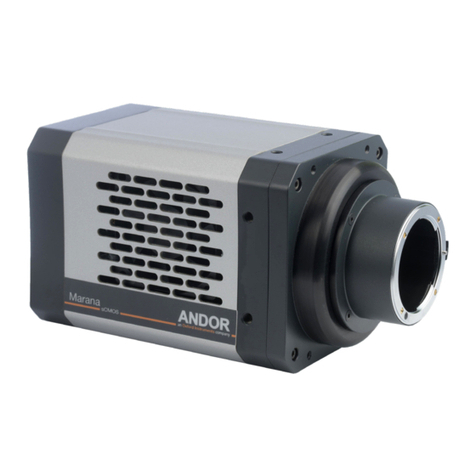
Andor Technology Zyla sCMOS 4.2 PLUS Installation instructions

version 2.0 rev 18 Feb 2021
2
SECTION 1: INTRODUCTION............................................................................................................ 8
1.1 Help and Technical Support.........................................................................................................................9
1.2 Disclaimer.............................................................................................................................................................. 10
1.3 Trademarks and Patent Information................................................................................................... 10
1.4 Components ......................................................................................................................................................... 11
1.4.1 Accessories................................................................................................................................................................................11
1.5 Power And Signal Connections................................................................................................................12
1.5.1 Power Supply Unit (PSU) ................................................................................................................................................12
1.5.2 Connectors................................................................................................................................................................................. 13
1.5.3 Multi I/O Timing Cable Pin Outs................................................................................................................................ 13
1.5.4 Impedance Information ...................................................................................................................................................14
1.5.5 Other Connections................................................................................................................................................................14
1.6 Cooling Hose Connectors (Water Cooled Models only)..........................................................15
1.6.1 Important Considerations when using Cooling Systems.......................................................................15
SECTION 2: FEATURES AND FUNCTIONALITY..................................................................16
2.1 sCMOS Structure and Operation.............................................................................................................16
2.2 Rolling and Global Shutter .........................................................................................................................17
2.2.1 Rolling Shutter......................................................................................................................................................................... 18
2.2.2 Global Shutter (Zyla 5.5 only)......................................................................................................................................19
2.2.3 Selecting Rolling or Global Shutter......................................................................................................................... 20
2.2.3.1 Examples of Typical Applications for Global Shutter Mode.................................................. 20
2.2.4 Rolling and Global Shutter Mechanisms............................................................................................................ 21
2.3 Understanding Read Noise in sCMOS................................................................................................22
2.3.1 Spurious Noise Filter........................................................................................................................................................... 23
2.3.2 Blemish Correction...............................................................................................................................................................23
2.4 DualAmplierDynamicRange..............................................................................................................24
2.5 Sensor Readout Optimization ..................................................................................................................26
2.5.1 Gain Channel Control ........................................................................................................................................................26
2.5.2 Pixel Readout Rate ............................................................................................................................................................. 27
2.5.3 ROI Sub-Image Settings ..................................................................................................................................................27
2.6 Trigger Modes .....................................................................................................................................................28
2.6.1 Example System Usage of Acquisition Events...............................................................................................29
2.6.2 Rolling Shutter Triggering Modes .............................................................................................................................30
2.6.2.1 Timing Parameters and Ext Triggering for Zyla 5.5 ....................................................................31
2.6.2.2 Timing Parameters and Ext Triggering for Zyla 4.2......................................................................31
2.6.2.3 Rolling Shutter Internal Triggering (Non-Overlap Mode) ........................................................32

version 2.0 rev 18 Feb 2021
3
2.6.2.4 Rolling Shutter Internal Triggering (Overlap Mode) ..........................................................................33
2.6.2.5 Rolling Shutter External / Software Triggering (Non Overlap Mode)..................................35
2.6.2.6 Rolling Shutter External Exposure Triggering (Non-Overlap Mode) ...................................36
2.6.2.7 Rolling Shutter External Exposure Triggering (Overlap Mode).................................................37
2.6.2.8 Rolling Shutter External Start Triggering...................................................................................................38
2.6.2.9 Rolling Shutter Global Clear Internal (Non-Overlap Mode)- Zyla 4.2 only.....................39
2.6.2.10 Rolling Shutter Global Clear External/Software Triggering (Non-Overlap Mode)
- Zyla 4.2 Only........................................................................................................................................................................................40
2.6.2.11 Rolling Shutter Global Clear External Exposure Triggering (Non-Overlap Mode)
- Zyla 4.2 Only........................................................................................................................................................................................41
2.6.2.12 Rolling Shutter Triggering Constraints ........................................................................................................42
2.6.3 Global Shutter Triggering Modes (Zyla 5.5 only)..............................................................................................43
2.6.3.1 Global Shutter Internal Triggering (Non-Overlap Mode) ..............................................................44
2.6.3.2 Global Shutter Internal Triggering (Overlap Mode)...........................................................................46
2.6.3.3 Global Shutter External/Software Triggering........................................................................................47
2.6.3.4 Global Shutter External Exposure Triggering (Non-Overlap Mode).....................................49
2.6.3.5 Global Shutter External Exposure Triggering (Overlap Mode).................................................50
2.6.3.6 Global Shutter External Start Triggering ...................................................................................................51
2.6.3.7 Global Shutter Triggering Constraints.........................................................................................................52
2.7 ACQUISITION MODES ......................................................................................................................................53
2.7.1 Single Scan....................................................................................................................................................................................53
2.7.2 Kinetic Series ................................................................................................................................................................................53
2.7.3 Accumulate ...................................................................................................................................................................................53
2.7.4 Run Till Abort Acquisition....................................................................................................................................................53
2.7.4.1 Live Mode..........................................................................................................................................................................54
2.7.5 Fast Exposure Switch ............................................................................................................................................................54
2.7.6 Frame Rate Control ................................................................................................................................................................54
2.7.7 LightScan PLUS..........................................................................................................................................................................54
2.7.7.1 Multiple Readout Directions ...............................................................................................................................54
2.7.7.2 FlexiScan............................................................................................................................................................................55

version 2.0 rev 18 Feb 2021
4
SECTION 3: INSTALLATION ..............................................................................................................56
3.1 Safety Considerations......................................................................................................................................56
3.2 Camera Mounting..............................................................................................................................................56
3.3 Coolant Hose Connection and Disconnection (Water Cooled Models) ..........................57
3.3.1 Coolant Recommendations............................................................................................................................................. 57
3.3.2 Connecting the Coolant Hoses ..................................................................................................................................... 58
3.3.3 Disconnecting the Coolant Hoses............................................................................................................................... 58
3.4 Recommended Computer Requirements...........................................................................................58
3.5 Installing Software (Solis or SDK3) .........................................................................................................59
3.6 Installing the Camera Framegrabber Card...................................................................................... 60
3.7 Checking & Setting BIOS options (for PCs not supplied by Andor) ..................................... 61
3.8 Software Support................................................................................................................................................ 61
SECTION 4: OPERATION.....................................................................................................................62
4.1 Connecting your Camera and Switching it on .................................................................................62
4.2 Using the Lens Mount Adaptors................................................................................................................63
4.2.1 C-mount Adaptor..................................................................................................................................................................... 63
4.2.2 CS-mount Adaptor.................................................................................................................................................................. 64
4.2.3 F-mount Adaptor...................................................................................................................................................................... 64
4.3 Cooling .......................................................................................................................................................................65
4.3.1 Integral Thermal Protection............................................................................................................................................. 65
4.3.2 TE Cooling (Air-Cooled Models).................................................................................................................................... 65
4.3.3 TE Cooling (Water Cooled Models) .......................................................................................................................... 65
4.4 Emergency Mains Disconnection .............................................................................................................66
SECTION 5: MAINTENANCE.............................................................................................................67
5.1 Regular Checks.....................................................................................................................................................67
5.2 Annual Electrical Safety Checks...............................................................................................................67
5.3 Fuse Replacement .............................................................................................................................................67
5.4 Zyla Chamber Design And Service Guidance..................................................................................67
5.5 Cooling Hoses and Connections...............................................................................................................68

version 2.0 rev 18 Feb 2021
5
SECTION 6: TROUBLESHOOTING ................................................................................................... 69
6.1 Camera buzzer does not sound on start-up.........................................................................................69
6.2 Camera is not recognized by PC ...................................................................................................................69
6.3 Buzzer sounds continuously ............................................................................................................................69
6.4 Fan not operating as expected......................................................................................................................69
6.5 Camera does not cool to the required temperature .......................................................................69
6.6 Fire, Aux_Out and Arm outputs not functioning correctly.............................................................70
6.7 External Trigger input not functioning correctly.................................................................................70
6.8 Condensation Appearing On Exterior Of Camera (Water Cooled Model)..........................70
6.9 CondensationEectNoticeableinImages.............................................................................................71
APPENDIX A: SPECIFICATIONS...........................................................................................................72
APPENDIX B: MECHANICAL DRAWINGS..................................................................................... 75
APPENDIX C: DEW POINT GRAPH ................................................................................................... 77
APPENDIX D: OTHER INFORMATION .............................................................................................78

version 2.0 rev 18 Feb 2021
6
SAFETY AND WARNING INFORMATION
PLEASE READ THIS INFORMATION FIRST BEFORE USING YOUR ZYLA sCMOS CAMERA.
1. To ensure correct and safe operation of this product, please read this guide before use and keep it in a safe place for
future reference
2. IfequipmentisusedinamannernotspeciedbyAndor,theprotectionprovidedbytheequipmentmaybeimpaired
3. Before using the system, please follow and adhere to all warnings, safety, manual handling and operating instructions
located either on the product or in this Hardware Manual
4. TheAndorZylaisaprecisionscienticinstrumentcontainingfragilecomponents.Alwayshandlewithcare
5. Do not expose the product to extreme hot or cold temperatures
6. For air-cooled models, ensure that a minimum clearance of approximately 100 mm (4”) is maintained in front of all
ventilation slots and the fan inlet
7. For water-cooled models, ensure that cooling water supply is connected prior to powering the camera.
8. Donotexposetheproducttoopenames
9. Do not allow objects to fall on the product
10. Do not expose the product to moisture, wet or spill liquids on the product. Do not store or place liquids on the product. If
aspillageoccursontheproduct,switchopowerimmediately,andwipeowithdry,lint-freecloth.Ifanyingresshas
occurred or is suspected, unplug mains cable, do not use, and contact Andor service
11. The product contains components that are extremely sensitive to static electricity and radiated electromagnetic
elds,andthereforeshouldnotbeused,orstored,closetoEMI/RFIgenerators,electrostaticeldgenerators,
electromagneticorradioactivedevices,orothersimilarsourcesofhighenergyelds
12. Operation of the system close to intense pulsed sources (e.g. plasma sources, arc welders, radio frequency generators,
X-ray instruments, and pulsed discharge optical sources) may compromise performance if shielding of the Zyla is
inadequate
13. This product is not designed to provide protection from ionising radiation. Any customer using this product in such an
application should provide their own protection
14. TheAndorZylaisforuseinresearchlaboratoriesandothercontrolledscienticenvironments
15. This equipment has not been designed and manufactured for the medical diagnosis of patients
16. Use only the power supply cord provided with the system for this unit. Should this not be correct for your geographical
area contact your local Andor representative
17. Onlythecorrectlyspeciedmainssupplyandfusemustbeused
18. Make sure the electrical cord is located so that it will not be subject to damage
19. Therearenouser-serviceablepartsbeyondthespecieduseraccessibleareasoftheproductandtheenclosuremust
not be opened. Only authorised service personnel may service this equipment
20. The above label indicates that this unit contains components which are sensitive to and can be damaged by
electrostatic discharge. When working on a unit which is not enclosed it is necessary to follow anti static precautions to
ensure damage does not occur.
Regulatory Compliance
The Zyla 4.2 and Zyla 5.5s CMOS Cameras comply with the requirements of the EU EMC and LV Directives
through testing to EN 61326-1 and EN 61010-1.
This product requires a DC power supply (refer to Section 1.6)
This product complies with international EMC standards, but please note that this includes a permissible loss of
performance as allowed by EN 61326 1:2013 and IEC 61326 1:2012 for a defect that rarely occurs during 4 kV
contact ESD strikes. This issue manifests itself in the worst case as one row experiencing 5 times the typical noise that
persists for the duration of a kinetic series, but disappears thereafter. This issue is theoretical and has never been seen
during normal use

version 2.0 rev 18 Feb 2021
7
Revision History
Version Released Description
1.0 17 Jul 2012 Initial Release
1.1 29 Oct 2012 General minor updates throughout.
1.2 15 Oct 2013
General enhancements to presentation (all Sections)
Text revised to improve clarity of information (all Sections.
Zyla Components revised to show standard supplied components more clearly (Section 1.5)
Additional accessories revised to match current options available (Section 1.5.1)
Additional information added for use for lens mount adaptors (Section 4.2)
Updated timing diagrams and tables for Rolling and Global Shutter Modes (Section 2)
Updated to show 12-bit data range and gain channels options (Sections 2.6 and 2.7)
1.3 16 Jan 2014
Added Information to support the Zyla 4.2 model (all Sections).
Added Rolling Shutter Global Clear modes (Section 2.6)
Timing data updated to align with current data (Section 2.6)
1.4 13 Feb 2014
Information added for Water Cooled Zyla models (all Sections).
FurtherinformationonframerateperformanceforeachmodelunderdierentshutterandROI
modes added (Section 2.5)
1.5 09 Jun 2014
Updates to include support for Zyla USB 3.0 model (All Sections)
Added new section to cover disabling USB host controller power management (Section 3.7.1)
Updated frame rates table for USB 3.0 models (Section 2.5)
Updated presentation throughout to match current company branding
Updated Figures 4 (Section 1.6.4), 7( Section 2.1) and 12 (Section 2.4) to enhance quality
Included updates to show support for Windows 8 (Sections 3.4 and 3.7)
1.6 15 Sep 2014 Updated accessories list to show that longer lengths of USB 3.0 cable are available, but not sup-
pliedorveriedbyAndor(Section1.5.1)
1.7 03 Feb 2015
UpdatedinformationforZyla5.5model:lowvibrationfan(asusedinZyla4.2)ttedtoair-cooled
units from February 2015 onwards, max. Ambient temperature changed to 30oC.
Edited Mechanical drawing for water cooled models to show distance from C-mount to camera
faceplate when installed is 6mm nominal.
1.8 17 Nov 2015
Revised Rolling Shutter Sections (Section 2.6.2.3 to 2.6.3.12)
Corrected cross-reference to Mechanical Drawings (Section 3.2)
Mechanical drawings updated (Appendix A)
1.9 01 Feb 2016 Updated PCI slot for USB Card to x4 or greater- previously was x4 only (Sections 3.4 and 3.6).
1.10 19 May 2016 Added BIOS options checking and setting for Camera Link models used with non-Andor supplied
PCs (Section 3.8).
1.11 10 Jun 2016 Added note regarding a potential loss of performance in an ESD strike event (Safety and Warning
Section)
1.12 12 Sep 2017
Expanded cooling information for water cooled models (Section 3.3, Appendix B)
AddedEmergencypowerosection(Section4.5)
Updated software, PCIe cards and PC requirements to current spec.
Added part numbers for power connector and socket (Section 1.6.5)
1.13 11 Apr 2019 UpdatedUSAandAsia-Pacicaddresses(page9)andfrontcover.
1.14 13 Jun 2019
Updated mechanical drawings of back view of USB3, water cooled and Camera Link Zyla vari-
ants (Appendix A). Updated back view images of Zyla (Section 1.6.2). Minor updates to format
throughout.
1.15 16 Apr 2020 UpdatedChinaoceaddress,updatedfrontcover.
2.0 18 Feb 2021
Added new sections 2.7.7 LightScan PLUS, 5.4 Zyla Chamber Design, Service Guidance and 6.9
CondensationEectNoticeableinImages.AddedAppendixAwithtechnical,general,
environmental,andpowerspecications.Updatedbrandingthroughout.
Updates to the Manual
Changes are periodically made to the product and these will be incorporated into new editions of the manual.
Please check for new releases of the manual at: andor.oxinst.com/downloads.Ifyoundanissueinthismanual
please contact your customer support respresentative (Section 1.1) with a description of the issue.

version 2.0 rev 18 Feb 2021
8
SECTION 1: INTRODUCTION
Thank you for choosing the Zyla Scientic CMOS (sCMOS) camera. You are now in possession of a
revolutionary new sCMOS camera, a breakthrough technology based on the next-generation CMOS image
sensor(CIS)designandfabricationtechniques.Thecameraoerstwoimagesensorsof5.5Megapixels(Zyla
5.5) and 4.2 Megapixels (Zyla 4.2). It is available in both air cooled, and water cooled forms and with Camera
Link and USB 3.0 connection options.
Figure 1: The Zyla sCMOS Camera. Left: Water Cooled model, right: air cooled model
TheZylasCMOScameraoers:
• Extremely low noise
• Rapid frame rates
• Wide dynamic range
• Highquantumeciency(QE)
• High resolution
• Largeeldofview
This manual contains useful information and advice to ensure you get the optimum performance from your
new system. If you have any questions regarding your Zyla, camera please feel free to contact Andor directly,
or via your local representative or supplier.

version 2.0 rev 18 Feb 2021
9
1.1 Help and Technical Support
If you have any questions regarding the use of this equipment, please contact the representative* from whom
your system was purchased, or:
Europe USA
Andor Technology Ltd.
7 Millennium Way
Springvale Business Park
Belfast
BT12 7AL
Northern Ireland
Tel. +44 (0) 28 9023 7126
Fax. +44 (0) 28 9031 0792
Andor Technology
300 Baker Avenue
Suite # 150
Concord
MA 01742
USA
Tel. +1 (860) 290-9211
Fax. +1 (860) 290-9566
Asia-Pacic China
Andor Technology (Japan)
5F IS Building
3-32-42 Higashi-Shinagawa
Tokyo 140-0002
Japan
Tel: +81 3 6732 8968
Fax: +81 3 6732 8939
Andor Technology (China)
Haitong Times Business Center,
Building B2 West,
No.11 West Third Ring North Road,
Haidian District,
Beijing,
100089
China
Tel: +86 (0) 10 5884 7900
Fax. +86 (0) 10 5884 7901
* The latest contact details for your local representative can be found on the Contact and Support page of our website.

version 2.0 rev 18 Feb 2021
10
1.2 Disclaimer
THE INFORMATION CONTAINED HEREIN IS PROVIDED “AS IS” WITHOUT WARRANTY, CONDITION OR REPRESENTATION OF
ANY KIND, EITHER EXPRESS, IMPLIED, STATUTORY OR OTHERWISE, INCLUDING BUT NOT LIMITED TO, ANY WARRANTY OF
MERCHANTABILITY, NON-INFRINGEMENT OR FITNESS FOR A PARTICULAR PURPOSE.
IN NO EVENT SHALL ANDOR BE LIABLE FOR ANY LOSS OR DAMAGE, WHETHER DIRECT, INDIRECT, SPECIAL, INCIDENTAL,
CONSEQUENTIALOROTHERWISEHOWSOEVERCAUSEDWHETHERARISINGINCONTRACTTORTOROTHERWISE,ARISING
OUT OF OR IN CONNECTION WITH THE USE OF THE INFORMATION PROVIDED HEREIN.
COPYRIGHT AND PROTECTIVE NOTICES:
The copyright in this document and the associated drawings are the property of Andor Technology and all
rights are reserved. This document and the associated drawings are issued on condition that they are not
copied, reprinted or reproduced, nor their contents disclosed.
The publication of information in this documentation does not imply freedom from any patent or proprietary
right of Andor Technology or any third party.
1.3 Trademarks and Patent Information
Andor and the Andor logo are trademarks of Andor Technology Ltd. Andor Technology Ltd. is an Oxford
Instruments company. All other marks are property of their owners.
Manufacturers Information
Andor Technology Ltd., Belfast, BT12 7AL, UK.

version 2.0 rev 18 Feb 2021
11
1.4 Components
The standard components supplied with the Zyla are shown in Table 1:
Table 1: Standard Components supplied with the Zyla
1.4.1 Accessories
There are a range of optional and additional accessories available for Zyla including:
• Mounting Adapters (C-mount, CS-mount or F-mount)
• Re-circulator and Compact Chiller Units (water cooled models must be water cooled via some method)
• Camera Link Cables (5 meter and 10 meter active including power supply)
• Fibre-opticExtenders(30and100meterbre-opticextendersolutions)
• Software Development Kit (SDK)
• Solis Image Capture and Analysis Software
Note: Longer lengths of USB 3.0 cable are available from other suppliers such as Stemmer/CEI.
PleaseseetheZylaspecicationsorcontactAndororyournearestAndorrepresentativeforfurtherinformation.
Description Quantity
Zyla 5.5 or Zyla 4.2 sCMOS Camera
with Integral Lens Mount Adaptor
(C, CS or F-mount: as selected at time of ordering)
1
Description Quantity
PCIe Frame Grabber
Card 1
Camera to PC
Interface cables (s)
USB 3.0 and 3-tap
10-tap
1 x 3 m
2 x 3 m
Power Supply Unit
(PS12)
andCountryspecic
Power Cord
1
Multi I/O Timing cable 1 x 3 m
Coolant hose inserts
(for water cooled
models only)
2
Description Quantity
Anti-static Strap 1
Allen Key
(1.5 mm) 1
Electronic copy of
Hardware Guide 1
QuickStart
Guide 1

version 2.0 rev 18 Feb 2021
12
1.5 Power And Signal Connections
1.5.1 Power Supply Unit (PSU)
The Zyla camera is powered by a external 12 V DC Power Supply Unit (PSU). The Zyla camera is connected
via a 4 pin power connector - refer to Section 1.6.5. The external power supply has an IEC male socket that
requiresacertiedmainsleadwithanIECfemaleplugforconnectiontothemainselectricalsupply.
The Zyla PSU is for use with Telecommunications, Computer, Industrial Controller, and OA Systems and must
only be used indoors
The Zyla requires a Direct Current (DC) supply.
Figure 2: Power Supply Unit
NOTES:
1. Theelectricalmainsleadshouldbecertiedforuseinyourcountryandinapplicablecountriestheplug
mustbettedwitha240V5Afuse.
2. If users use any other power supply, they do so at their own risk.

version 2.0 rev 18 Feb 2021
13
1.5.2 Connectors
Figure 3: ZylaBackPlateConnections(Left)Cameralinkversions(Right)USB3.0
version
1.5.3 Multi I/O Timing Cable Pin Outs
Table 2: Multi I/O Timing Cable Pinouts 15-way D type connector
1ARM 9Reserved
2AUX_OUT_1 10 Reserved
3FIRE n 11 Reserved
4FIRE 12 Reserved
5AUX_OUT_2 13 Reserved
6Ground 14 Reserved
7External Trigger 15 Reserved
8Spare (I)
• External Trigger and Spare input are 5V TTL input. By default they trigger on a rising edge.
• Fire, Fire n, Arm, AUX_OUT_1 and AUX_OUT_2 outputs are all TTL timing outputs (please also refer to
Section 1.6.4 for information on impedance matching)
• TTL I/O can be individually inverted via software (e.g. Solis or SDK)
• Pins 9 to 15 are reserved and should not be used.
• AUX_OUT_1 supplies the ‘FIRE ALL’ output by default. This is the logical AND of the FIRE pulses associated
with Row #1 and Row #n (the last row read out in the image frame). Therefore the FIRE ALL pulse
represents the time within a frame when all rows on the sensor are simultaneously exposing.
AUX_OUT_1isalsocongurableasFIRE,FIREnandFIREANY.TheFIRE ANY pulse represents the time
within a frame when any row of the image frame is exposing. Refer to Section 2.6 for the behaviour of
thesesignalsandtotheSDK3manualforconguringtheAUX_OUT_1output.
NOTE: This congurable output is only available on cameras with FPGA version numbers ≥ 20120802
and Solis versions ≥ 4.22.30001.0 (SDK users require version ≥ 3.5.30001.0).
• AUX_OUT_2 output is reserved for future use.
• I/O Timing Interface cable (Andor part number ACC-ACZ-05612) gives access to all of the above I/O
functions (excluding Ground and Reserved).
12V 5A
Max
OFFON
I/O
USB
3.0
Made in UK
11
2
2
3
4
55
6
1. I/O 15-Way D Type
Connector
2. 12V DC Power
Connector
3. CL1 connector
4. CL2 connector (Not
present on 3-tap
version)
5.On/OSwitch
6. USB 3.0 Connector

version 2.0 rev 18 Feb 2021
14
1.5.4 Impedance Information
Figure 4: Zyla Connection Impedance Information
1.5.5 Other Connections
• CL1: This is the connection for the 3-tap (single cable) Camera Link version of the Zyla camera.
• CL2: This connection is required for the full 10-tap (double cable) Camera Link version of the Zyla 5.5
and Zyla 4.2 camera and is not present on the Zyla 5.5 3-tap version.
•USB 3.0: This is the connection for the USB 3.0 version of the Zyla camera. It is not present on the
Camera Link versions.
• Power:A4pinpowerconnectoristtedforpowerconnection,detailsareshownbelow:
Figure 5: (Left, Camera Connection) and (Right, Connector socket)
Connector: Cable Plug: P/N #6-1437719-4, Socket: P/N #3-1437719-3 (TE Connectivity).
WARNING: Ensure that the power switch is in the ‘OFF’ position and the connector orientation is correct
before inserting the power connector. The power connector is ‘keyed’ - Never forcibly insert the connector
otherwise damage to the equipment may occur.
+12v +12v-ve
-ve
Cable alignment key Cable alignment key
Ext Trigger & Spare Inputs
Arm, Fire, Fire n and AUX_OUT Outputs
Zyla Camera
Zyla Camera
5V
1K Ohms
5K6 Ohms
> 2.0V
< 0.8V
> 1K Ohms
5V
15 Ohms
> 2.4V Logic level 1
< 0.8V Logic level 0
Input triggers on
posiitve edge

version 2.0 rev 18 Feb 2021
15
1.6 Cooling Hose Connectors (Water Cooled Models only)
TT
There are two connectors to allow connection of Water Cooled Zyla models to a water cooler or
re-circulator. Hose inserts are provided to enable connection to coolant hoses.
Figure 6: Zyla Cooling Hose Connectors
Please refer to Section 3.3 for details of connector and hose type compatibility and for connection and
disconnection information.
1.6.1 Important Considerations when using Cooling Systems
• Always ensure that the temperature of the liquid coolant circulated through the camera head is
above the dew point of the camera ambient temperature and humidity conditions. Refer to the dew
point graph in Appendix C for guidance.
• Use of coolant at or below the dew point can result in permanent damage to the camera head, due
to formation of condensation on internal components.
• In the event that replacement hose inserts / barbs are required, please contact your local Andor
representative.
Coolant pipes for
connection to water
cooler or re-circulator

version 2.0 rev 18 Feb 2021
16
Horizontal Scan Circuit
Vertical Scan Circuit
APS with column A/D
Photodiodes + Ampliers + Switches
SECTION 2: FEATURES AND FUNCTIONALITY
2.1 sCMOS Structure and Operation
sCMOStechnologyhasbeendevelopedspecicallytoovercomemanyofthelimitationsthathavemarred
otherscienticdetectortechnologies,resultinginanimagingdetectorthatprovidesexceptionalperformance
for many applications.
Figure 7: sCMOS Sensor Architecture
As illustrated above, the CMOS sensor is an “Active Pixel Sensor” (APS) whereby each pixel has its own integral
amplierandthesequenceofoperationisasfollows:
1. Light hits sensor and generates charge
2. Thephoto-generatedchargeisconvertedtoananalogvoltageinsideeachpixelamplier
3. Pixel voltage is transferred to the column bus via a row select signal
4. The analog voltage is then converted to a digital signal via columns of A/D (analog to digital) converters.
5. Thenaldigitizedsignalsarethenreadoutsequentiallyatapixelreadoutspeedofupto280MHz
fortheZyla5.5and270MHzfortheZyla4.2(inx2halves).
NOTES:
The diagram, above is representative- the light sensitive area is contiguous as the photodiodes for each
pixel are buried within the sensor. Each pixel also has a microlens to maximize sensitivity to light.
For Rolling Shutter mode operation, pixels in each row are exposed and the charge converted to a voltage
simultaneously before being digitized then read out sequentially
For Global Shutter mode, each pixel in the sensor begins an exposure simultaneously and then ends this
exposure simultaneously
1
23
45

version 2.0 rev 18 Feb 2021
17
2.2 Rolling and Global Shutter
ThesCMOSsensorusedbytheZyla5.5oersachoiceofbothRollingandGlobalshutter,providingsuperior
applicationexibility.RollingandGlobalshuttermodesdescribetwodistinctsequencesthroughwhichthe
imagemaybereadoasCMOSsensor.Inrollingshutter,chargeistransferredfromeachrowinsequence
duringreadout,whereasinglobalshuttermodeeachpixelinthesensoreectivelyendstheexposure
simultaneously. However, lowest noise and fastest frame rates are achieved from rolling shutter mode.
Traditionally,mostCMOSsensorsoereitheroneortheother,butveryrarelydoestheuserhavethechoice
of both from the same sensor. For the Zyla 5.5, it is possible to select between either readout mode from the
samesensor,sothemostappropriatemodecanbeselectedforthespecicapplication.TheZyla4.2oers
Rolling Shutter only.

version 2.0 rev 18 Feb 2021
18
2.2.1 Rolling Shutter
InRollingShuttermode,adjacentrowsofthearrayareexposedatslightlydierenttimesasthereadout
‘waves’ sweep through each half of the sensor. Therefore, each row will start and end its exposure slightly
osetintimefromitsneighbour.InthecaseoftheZyla5.5,atthemaximumreadoutrateof560MHz(aseach
halfofthesensorisat280MHz),thisosetbetweenadjacentrowexposuresis~10μs.Therollingshutter
readout mechanism is illustrated in Figure 8 below. From the point of view of readout, the sensor is split in half
horizontally.Rowsarereadoutfromthecentreoutwards,rowafterrow.Atthestartofanexposure,thewave
sweeps through each half of the sensor, switching each row in turn from a ‘keep clean state’, in which all charge
is drained from the pixels, to an ‘exposing state’, in which light induced charge is collected in each pixel. At the
end of the exposure, the readout wave again sweeps through the sensor, transferring the charge from each
row into the readout node of each pixel. The important point is that each row will have been subject to exactly
the same exposure time, but the row at the top (or bottom) edge of the sensor would have started and ended
itsexposure~10ms(1080rowsx10μs/row)aftertherowsatthecentreofthesensor(whenusing560MHz
readout rate).
Figure 8: Rolling Shutter Exposure and Readout
Rolling shutter can be operated in a ‘continuous’ mode when capturing a kinetic series of images, whereby
after each row has been read out it immediately enters its next exposure. This ensures a 100% duty cycle,
meaning that no time is wasted between exposures and, perhaps more importantly, no photons are wasted.
Atthemaximumframerateforagivenreadoutspeed(e.g.100fpsat560MHzfortheZyla5.5)thesensor
is continuously reading out, i.e. as soon as the readout fronts reach the top and bottom of the sensor, they
immediately return to the centre to readout the next exposure.
A potential downside of rolling shutter is spatial distortion resulting from the above described exposure
mechanism. This has historically been more apparent in devices such as CMOS camcorders, where the entire
imageeldcouldbemoved(forexamplebytheuserrapidlypanningthecamera)ataratethattheimage
readout could not match; thus, objects could appear at an angle compared to their actual orientation. In
reality,despitethetime-osetreadoutpattern,rollingshuttermodeisappropriateforthemajorityofscientic
applications, especially where the exposure time is equal to or greater than the sensor readout time, discussed
later.

version 2.0 rev 18 Feb 2021
19
2.2.2 Global Shutter (Zyla 5.5 only)
Global shutter mode, which can also be thought of as a ‘snapshot’ exposure mode, means that all pixels of
the array are exposed simultaneously. In most respects, global shutter can be thought of as behaving like an
Interline CCD sensor. Before the exposure begins, all pixels in the array will be held in a ‘keep clean state’, during
which charge is drained into the anti-bloom structure of each pixel. At the start of the exposure each pixel
simultaneously begins to collect charge and is allowed to do so for the duration of the exposure time. At the
end of exposure each pixel transfers charge simultaneously to its readout node. Importantly, global shutter can
beconguredtooperateinacontinuous‘overlap’mode(analogoustoInterlineCCD),wherebyanexposurecan
proceed while the previous exposure is being readout out from the readout nodes of each pixel. In this mode,
thesensorhasa100%dutycycle,againresultinginoptimaltimeresolutionandphotoncollectioneciency.
However, the mechanism of global shutter mode demands that a reference readout is performed ‘behind the
scenes’, in addition to the actual readout of charge from each pixel. Due to this additional reference readout,
globalshuttermodecarriesthetrade-oofhalvingthemaximumframeratethatwouldotherwisehavebeen
achieved in rolling shutter mode. In addition, global shutter also increases the RMS read noise by a factor of
1.41 over rolling shutter readout. Figure 9belowshowsasimpliedillustrationshowingsequenceofeventsin
global shutter mode:
Figure 9: Global Shutter Exposure and Readout

version 2.0 rev 18 Feb 2021
20
2.2.3 Selecting Rolling or Global Shutter
TheselectionofRollingShutterorGlobalShuttermodesfortheZyla5.5dependsonyourspecicexperimental
conditions. A summary of the key parameters for each mode is shown in Table 3.
Table 3: A Comparison of Rolling and Global Shutter Modes
Parameter Rolling Shutter Mode Global Shutter Mode (Zyla 5.5 only)
Frame Rate Maximum available Maximum frame rate is halved
Read Noise Lowest Increased by 1.41
Spatial Distortion Dependent on object dynamics and frame rate None
Rolling Shutter Mode:withtheenhancedframeratesandlowernoise,islikelytosuitthemajorityofscientic
applications. As long as the frame rate is such that the camera is temporally oversampling object dynamics
within the image area, negligible spatial distortion will be observed. Such oversampling is good imaging
practice,sinceitisundesirabletohaveanobjecttravelasignicantdistanceduringasingleexposure.
Global Shutter Mode:forsomespecicapplicationsglobalshutterwillbeviewedasanecessity.Theseare
shown in Section 2.2.3.1.
Refer also to Andor Technical Note, “Rolling and Global Shutter”.
2.2.3.1 Examples of Typical Applications for Global Shutter Mode
• Applications that require ‘microsecond’ time gating synced to a pulsed light source: e.g. Laser
Induced Breakdown Spectroscopy (LIBS). Global readout involves a step that simultaneously transfers
the signal charge of each pixel into the corresponding readout node for that pixel. This transfer step is
2μs(at560MHzreadoutrate),facilitatingfastexposureend,i.e.‘Electronicgating’
• ‘Double Exposure’ applications: e.g. Particle Imaging Velocimetry (PIV), which requires that two back-
to-backexposuresareacquiredwithminimaltimeseparationbetweenthem.Theglobalshutter2μs
transfertimeintothereadoutnodedenestheminimumtimebetweentwoconsecutiveexposures
• Applications that require exact time correlation between two (or more) points of an image that
are separated vertically within the image: Inrollingshutterittakes10μsperrowforthe2xreadout
frontstomoveacrosstheimagefromthecentreoutwards,readingoutonerowatatime.At560MHz
pixel readout rate, this represents 10 ms to cover the distance from centre to outermost rows. That
meansanobjectatthecentreoftheimagewillbeginandendanexposure~10msbeforeanobject
located at the very top or bottom (although remember that each object will be subject to the same
overall exposure time). If a particular application requires that ‘moving or changing’ objects separated
by relatively large distances (vertically) be subject to the same beginning and end of exposure, then
global shutter mode is required
• Applications where the entire eld of view is fast moving (relative to exposure time): e.g. high speed
machine vision inspection, such as PCB inspection
This manual suits for next models
1
Table of contents
Other Andor Technology Measuring Instrument manuals