Lotus cooker BR-50-78G User manual

INSTRUCTION FOR
INSTALLATION AND USE
GAS TILTING BRATT PANS
BR-50-78G, BR-50-78GE, BRM-50-78G, BRM-50-78E
BR-80-98G, BR-80-98GE, BRM-80-98G, BRM-80-98GE
BR-120-912G, BR-120-912GE, BRM-120-912G, BRM-120-912GE
563029400.docx
LIBR.ISTR.BRG50200 80-120100 AI
Date:
06/2012

2
Content
Content............................................................................................................................................................................. 2
Declaration of a standards conformity ........................................................................................................................ 7
Technical data ................................................................................................................................................................. 7
Basic information about pans ....................................................................................................................................... 9
Packing and device check ............................................................................................................................................ 9
Overall guidance ............................................................................................................................................................. 9
Installation ..................................................................................................................................................................... 10
Placement ...................................................................................................................................................................... 10
Chimney design for an appliance –type A (Fig. 8) .................................................................................................. 11
Safety measures from standpoint of the fire protection Act. No. EN 061008 COLL. 12 ................................... 11
Connect gas hose connection.................................................................................................................12
Water connection .....................................................................................................................................12
Measures for the rebuilding and installing a different type of gas ........................................................................ 12
Instruction for use ......................................................................................................................................................... 14
System of bath tilting...............................................................................................................................15
Maintenance and product warranty ........................................................................................................................... 16
Table of technical data burners .................................................................................................................................. 17
Dimensional drawings with connection points BR 80 – 98 (Fig.1) ....................................................................... 19
Dimensional drawings with connection points BR 120 – 912 (Fig. 1a) ................................................................ 20
Controlling (Fig. 2) ........................................................................................................................................................ 20
Gas valve, nozzles and burners (Fig. 3) ................................................................................................................... 21
Pilot burner (Fig. 4) ...................................................................................................................................................... 21
Positions gas valve control knob (Fig. 6) .................................................................................................................. 22
Gas valve (Fig. 5) ......................................................................................................................................................... 23
Wiring diagram (Fig. 7) ................................................................................................................................................ 24
Wiring diagram for electric tilting pan ........................................................................................................................ 25
Erklärung über Einklang mit Normen......................................................................................................27

3
Technische Angaben................................................................................................................................27
Grundlegende Informationen zu den Kipppfannen ................................................................................................. 29
Allgemeine Hinweise................................................................................................................................29
Installation ................................................................................................................................................30
Unterbringung ............................................................................................................................................................... 30
Ausführung des Abzugs Gerät vom Typ A (Abb. 8) ................................................................................................ 31
Anschluss des Gasanschlussschlauchs ................................................................................................................... 32
Wasseranschluss ............................................................................................................................................................. 33
Maßnahmen für den Umbau und die Installation auf eine andere Gassorte ...................................................... 33
Gebrauchsanweisung .................................................................................................................................................. 35
Ki system der Wanne ................................................................................................................................................... 36
Reinigung..................................................................................................................................................36
Instandhaltung und Garantiebedingungen.............................................................................................37
Tabelle der technischen Daten Brennern ...............................................................................................38
Dimensional drawings with connection points BR 80 – 98 (Fig.1) ....................................................................... 40
Dimensional drawings with connection points BR 120 – 912 (Fig. 1a) ................................................................ 41
Controlling (Fig. 2) ........................................................................................................................................................ 41
Gas valve, nozzles and burners (Fig. 3) ................................................................................................................... 42
Pilot burner (Fig. 4) ...................................................................................................................................................... 42
Positions gas valve control knob (Fig. 6) .................................................................................................................. 43
Gas valve (Fig. 5) ......................................................................................................................................................... 44
Wiring diagram (Fig. 7) ................................................................................................................................................ 45
Déclaration de l´accord des normes .......................................................................................................................... 48
Coordonnées techniques ............................................................................................................................................ 48
Informations de base sur les marmites basculantes ...................................................................................................... 50
Contrôle d´emballage et d´appareil ........................................................................................................................... 50
Instructions générales ................................................................................................................................................. 50
Installation ..................................................................................................................................................................... 51

4
Emplacement ................................................................................................................................................................ 51
Le tirage de l’appareil de type A (image 8) .............................................................................................................. 52
Mesures de sécurité concernant la protection contre l´incendie selon EN 061008 .......................................... 52
Le branchement du tuyau de raccordement du gaz ............................................................................................... 53
Le raccordement de l‘eau ........................................................................................................................................... 53
Mesures pour la reconstruction et l’installation pour un autre type de gaz ........................................................ 54
Mode d’emploi ............................................................................................................................................................... 54
Le système de basculement de la cuve ........................................................................................................................... 55
Service et conditions de garantie ............................................................................................................................... 56
Table des graveurs de données techniques ............................................................................................................ 57
Dimensional drawings with connection points BR 80 – 98 (Fig.1) ....................................................................... 60
Dimensional drawings with connection points BR 120 – 912 (Fig. 1a) ................................................................ 61
Controlling (Fig. 2) ........................................................................................................................................................ 61
Gas valve, nozzles and burners (Fig. 3) ................................................................................................................... 62
Pilot burner (Fig. 4) ...................................................................................................................................................... 62
Positions gas valve control knob (Fig. 6) .................................................................................................................. 63
Gas valve (Fig. 5) ......................................................................................................................................................... 64
Wiring diagram (Fig. 7) ................................................................................................................................................ 65
Wiring diagram for electric tilting pan ........................................................................................................................ 66
Dichiarazione di conformita con le norme ................................................................................................................ 68
Dati tecnici ..................................................................................................................................................................... 68
Informazioni generali sulle brassiere ribaltabili ........................................................................................................ 70
Controllo dell ‘imballo e dell’apparecchio ................................................................................................................. 70
Avvertenze generali ..................................................................................................................................................... 70
Istallazione..................................................................................................................................................................... 71
Posizionamento ............................................................................................................................................................ 71
Scaricamento dei prodotti di combustion – apparecchio di tipo A ........................................................................ 72
Elementi di sicurezza dal punto di vista di protezione contro L´INCENDIO SECONDO LA NORMA EN
061008 ART. 12-2: ....................................................................................................................................................... 72

5
Allaciamento del tubo di alimentazione gas ............................................................................................................. 73
Allacciamento alla rete idrica ..................................................................................................................74
Trasformazione ad altri tipi di gas...........................................................................................................74
Istruzioni di uso ............................................................................................................................................................. 76
Sistema di ribaltamento della vasca .......................................................................................................77
Dimensional drawings with connection points BR 80 – 98 (Fig.1) ....................................................................... 80
Dimensional drawings with connection points BR 120 – 912 (Fig. 1a) ................................................................ 81
Controlling (Fig. 2) ........................................................................................................................................................ 81
Gas valve, nozzles and burners (Fig. 3) ................................................................................................................... 82
Pilot burner (Fig. 4) ...................................................................................................................................................... 82
Positions gas valve control knob (Fig. 6) .................................................................................................................. 83
Gas valve (Fig. 5) ......................................................................................................................................................... 84
Wiring diagram (Fig. 7) ................................................................................................................................................ 85
Declaration de conformidad con las normas ............................................................................................................ 88
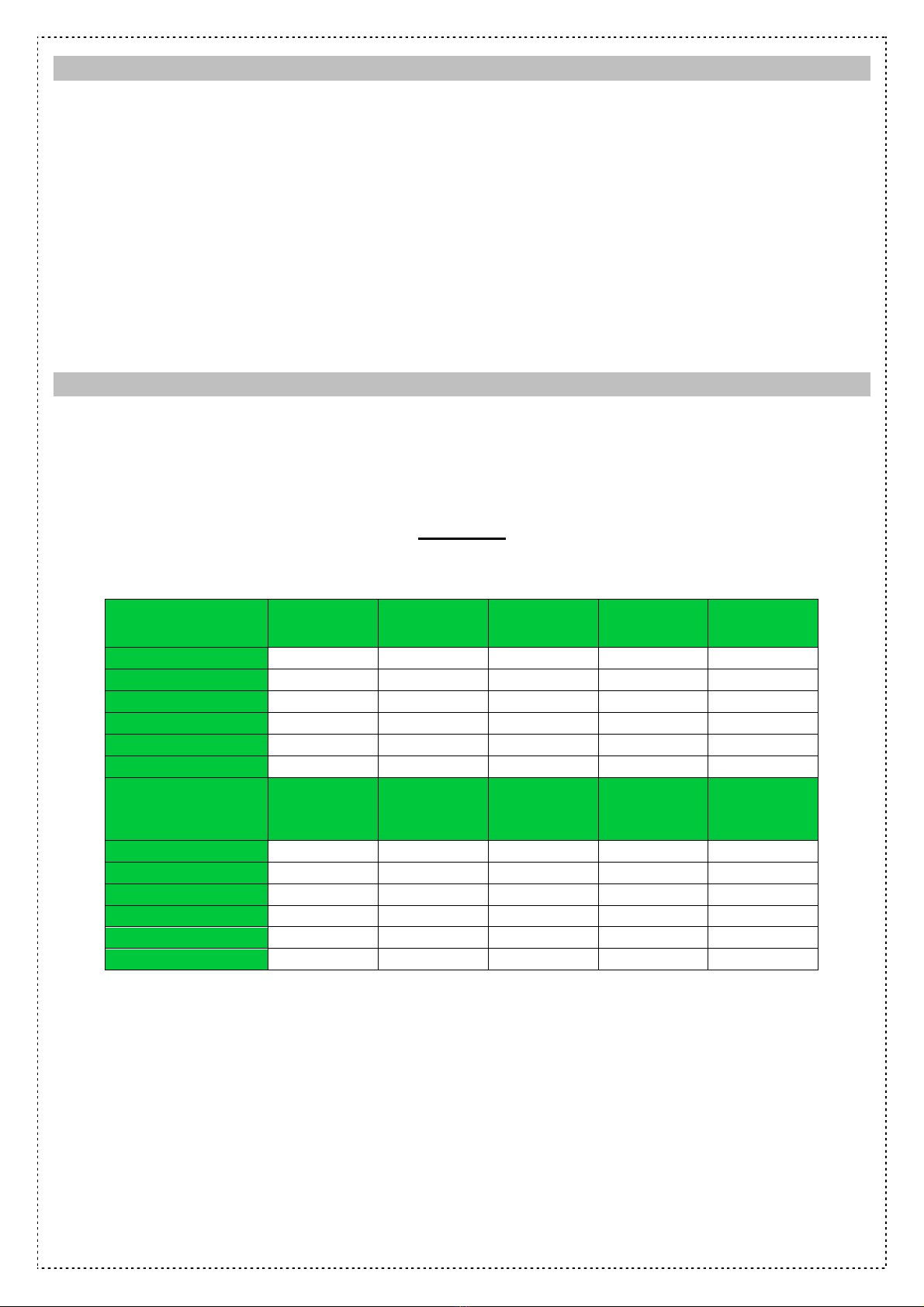
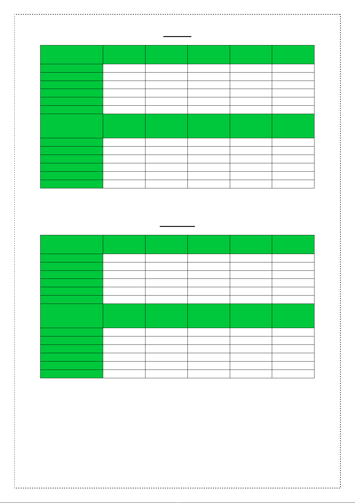
Datos tecnicos .............................................................................................................................................................. 88
Informaciones básicas sobre las sartenes basculantes ......................................................................................... 90
Control del envoltorio y del aparato ........................................................................................................................... 90
Instrucciones generales .............................................................................................................................................. 90
Instalacion ..................................................................................................................................................................... 91
Instrucciones técnicas para la instalación y regulación ................................................................................. 91
Importante: ................................................................................................................................................................... 91
Ubicación ....................................................................................................................................................................... 91
Realización de la evacuación de humos del aparato tipo A (fig. 8) ..................................................................... 92
Medidas de seguridad el aspecto de proteccion contra incendios de acuerdo a la norma EN 061008 art. 12-
2 ...................................................................................................................................................................................... 92
Conexión de la manguera conectora de gas ........................................................................................................... 93
Conexión del agua ....................................................................................................................................................... 94
Medidas para el cambio e instalación a otro tipo de gas. ...................................................................................... 94
Instrucciones de uso .................................................................................................................................................... 96

6
Sistema de volcado de la cuba .................................................................................................................................. 97
Advertencia ................................................................................................................................................................... 98
Dimensional drawings with connection points BR 80 – 98 (Fig.1) ..................................................................... 101
Dimensional drawings with connection points BR 120 – 912 (Fig. 1a) .............................................................. 102
Controlling (Fig. 2) ...................................................................................................................................................... 102
Gas valve, nozzles and burners (Fig. 3) ................................................................................................................. 103
Pilot burner (Fig. 4) .................................................................................................................................................... 103
Positions gas valve control knob (Fig. 6) ................................................................................................................ 104
Gas valve (Fig. 5) ....................................................................................................................................................... 105
Wiring diagram (Fig. 7) .............................................................................................................................................. 106

7
Declaration of a standards conformity
The manufacturer confirms, that the device agree with 2009/142/ES (government directive 22/2003),
directive no.22/1997 Coll. and no. 258/2000 Coll. about health public protection, directive no. 38/2001 Coll.
and relevant government orders. Installation must be made according to relevant directives.
Attention, the manufacturer reserves the right refuse any responsibility in case of direct or indirect damages
which are caused due wrong installation, incorrect intervention or modification, insufficient maintenance,
incorrect use and also possibly caused by other reasons presented by items in sale conditions. This
appliance must be operated by qualified person only. Parts that have been set by the manufacturer or an
authorized technician after setting, shall not to be modified by the user under any circumstances.
Technical data
The identification plate with the technical data is in a visible position on the side of the device. The plate
must not be removed. See the electrical diagram of connection and all following information before
installation.
BR – 50-78
Ty e of roduct Ignition Bath tilting
Material of
bath bottom Volume (l) Power (kW)
BR
-
50
-
78G
lighter
manual
Fe
50
14
BR
-
50
-
78GE
electric
manual
Fe
50
14
BR
-
50
-
78G/N
lighter
manual
INOX
50
14
BR
-
50
-
78GE/N
electric
manual
INOX
50
14
BRM
-
50
-
78G
electric
electric
Fe
50
14
BRM
-
50
-
78G/N
electric
electric
INOX
50
14
Ty e of roduct Voltage
(V/Hz)
Diameter gas
connection
Diameter
water
connection
Dimensions
(cm) Weight(kg)
BR
-
50
-
78G
-
G3/4
G1/2
80x70x90 v
133
BR
-
50
-
78GE
230/N/50
G3/4
G1/2
80x70x90 v
134
BR
-
50
-
78G/N
-
G3/4
G1/2
80x70x90 v
133
BR
-
50
-
78GE/N
230/N/50
G3/4
G1/2
80x70x90 v
134
BRM
-
50
-
78G
230/N/50
G3/4
G1/2
80x70x90 v
139
BRM
-
50
-
78G/N
230/N/50
G3/4
G1/2
80x70x90 v
139

8
BR 80-98
Ty e of roduct Ignition Bath tilting
Material of
bath bottom Volume (l) Power (kW)
BR
-
80
-
98G
lighter
m
anual
Fe
80
22
BR
-
80
-
98GE
e
le
ctric
m
anual
Fe
80
22
BR
-
80
-
98G/N
lighter
m
anual
INOX
80
22
BR
-
80
-
98GE/N
e
le
ctric
m
anual
INOX
80
22
BRM
-
80
-
98G
electric
electric
Fe
80
22
BRM
-
80
-
98G/N
e
lectric
electric
INOX
80
22
Ty e of roduct Voltage
(V/Hz)
Diameter gas
connection
Diameter
water
connection
Dimensions
(cm) Weight(kg)
BR
-
80
-
98G
-
G3/4
G1/2
80x90x90 v
155
BR
-
80
-
98GE
230/N/50
G3/4
G1/2
80x90x90 v
156
BR
-
80
-
98G/N
-
G3/4
G1/2
80x90x90 v
155
BR
-
80
-
98GE/N
230/N/50
G3/4
G1/2
80x90x90 v
156
BRM
-
80
-
98G
230/N/50
G3/4
G1/2
80x90x90 v
159
BRM
-
80
-
98G/N
230/N/50
G3/4
G1/2
80x90x90 v
159
BR 120-912
Ty e of roduct Ignition Bath tilting
Material of
bath bottom Volume (l) Power (kW)
BR
-
120
-
912G
lighter
manual
Fe
120
30
BR
-
120
-
912GE
e
le
ctric
manual
Fe
120
30
BR
-
120
-
912G/N
lighter
manual
INOX
120
30
BR
-
120
-
912GE/N
e
le
ctric
manual
INOX
120
30
BRM
-
120
-
912G
electric
electric
Fe
120
30
BRM
-
120
-
912G/N
e
le
ctric
electric
INOX
120
30
Ty e of roduct Voltage
(V/Hz)
Diameter gas
connection
Diameter
water
connection
Dimensions
(cm) Weight (kg)
BR
-
120
-
912G
-
G3/4
G1/2
120x90x90 v
203
BR
-
120
-
912GE
230/N/50
G3/4
G1/2
120x90x90 v
204
BR
-
120
-
912G/N
-
G3/4
G1/2
120x90x90 v
203
BR
-
120
-
912GE/N
230/N/50
G3/4
G1/2
120x90x90 v
204
BRM
-
120
-
912G
230/N/50
G3/4
G1/2
120x90x90 v
207
BRM
-
120
-
912G/N
230/N/50
G3/4
G1/2
120x90x90 v
207

9
Basic information about pans
Gas Pans are designed for maximum performance, resilience and reliability for the toughest
operations and ease of use combined with easy maintenance.
• High power burner 22 and 30 kW
• Optimized flame and gas consumption
• Stainless steel walls of baths and massive heat spread bottom
• Massive construction
• Manual or electric tilting
• Tilting models are set with direct water filling into the bath
• Ergonomic control shaping
• Optimized shape of surface for easy cleaning
• Easy for use
Packing and device check
The device leaves our warehouse properly packed with appropriate symbols and labels. There are also
appropriate instructions for use. In case the packing shows bad handling, damage or tampering, it should
be refused at forwarder immediately by writing and signing of a damage protocol. If not so, manufacturer
reserves the right deny any liability for any problems and hazards caused by that appliance in the
future.
Overall guidance
These instructions must be properly and carefully read, because it contains important information about the
security features, installation and use.
•These recommendations refer to this product or product line only
•This guide must be properly deposited for future use
•Keep the children away
•Only authorised person can operate the product
•Never leave device while in use unattended
•We strongly recommend having the device checked by professional service at least twice a year
•During operation, may never be fully or partially covered chimney flue
•Only original spare parts can be used for repairs
•The product cannot be cleaned by the water jet or pressure shower
•In the case of failure or malfunction, immediately disconnect device from gas, electricity and call
professional service
•The device may be used solely for the purpose for which is addressed, other use is prohibited and
may lead to danger or injury
•The device cannot be used under any circumstances as a fryer or its substitute
•manufacturer reserves the right refuse any responsibility in case of damages caused by wrong
installation, by disobeying of above mentioned recommendations or by violation of the rules of the
use

10
Installation
Important:
The manufacturer does not provide warranty for defects caused by improper use, failure to instructions
contained in the attached instructions for use and mistreatment of the appliances.
Installation, adjustment and repair of appliances for kitchens, as well as their removal because of possible
damage to the gas can be carried out only under a maintenance contract, this contract may be signed with
an authorized dealer, and must be complied with regulations and technical standards and regulations
regarding the installation, power supply, gas connection and health & safety system.
These instructions are intended for the qualified technician who must perform the installation, put it into
operation and test the appliance.
Any activity as settings, placement, rebalancing etc, must be made only when is device disconnected from
electricity and gas feeder. If it is necessary to have the device connected to the electricity or to gas feeder,
you must keep the highest attention to avoid any injuries
Type of appliance chimney design is declared on the identification plate, it is an appliance –type A1
(Fig.8)
Placement
The appliance may only be installed in permanently ventilated rooms, as specified by the standard TPG G
704 01, EN 127040 and EN 127010. In the room where the appliance is installed, there must be an
adequate air flow to meet the requirements of normal combustion of gas and the necessary ventilation of
the room itself. The room must be kept adequately ventilated in order to eliminate the heat and humidity
produced by cooking: in particular, after prolonged use, it is recommended to open window or to increase
the speed of ventilators.
If the device will be situated close to the wall, or if it will be in contact with the furniture walls, those walls
must resist temperatures ranging to 60°C. Installation, settings, putting into operation must be made by
qualified technician who is competent for this.
Extract the device and check whether it was not damaged during transport. Settle the appliance down on
horizontal surface (max. allowed imbalance 2 °C).
The device can be installed separately or in a set with other devices from our production. Minimal distance
10 cm from other subject must be kept.
This product cannot be installed in contact with combustible materials and must be installed or
stand on non combustible surface.

11
Chimney design for an appliance –type A (Fig. 8)
NATURAL EXTRACTION
FORCED EXTRACTION
Outlet hood with natural extraction (A). Flue
gas provides a natural chimney draft.
Outlet hood without natural extraction. Flue
gas is secured by a fan (D) (forced
extraction). In this case, it is necessary to
secure the connection with a gas feeder (B)
to turn off the gas supply in case of failure.
Safety measures from standpoint of the fire protection Act. No. EN 061008 COLL. 12
• The appliance is designed for use by adults
• Appliance may be safely used in a normal environment by Act No. EN 332000-1
• Appliance must be placed so as to stand on the non combustible surfaces
No subjects from combustible materials can be placed directly on the device or in distance which is shorter
than safety distance (the shortest allowed distance is 10 cm).
See Tab: combustion degree of building materials classified according to the combustion degree of
materials and product Act No. (EN 730823)
A – non combustible Granite, sandstone, concretes, bricks, ceramic, wall facing tiles
B – uneasily combustible acumen, Heraclites, lihnos, itavere
C1 – ha dly combustible Leafy wood, lywood, sirkoklit, rare a er, Formica
C2 – middle combustible fibreboards, solodure, cork boards, rubber, floor- coverings
C3 – easily combustible Wood-fibreboards, olystyrene, olyurethane, PVC
Appliances must be installed in a safe way. When installing you must respect corresponding project, safety
and hygienic orders according to:

12
•Act No. EN 06 1008 fire protection of local device and sources of heat
•Act No. EN 33 2000 environment for electric devices
Connect gas hose connection
It must first determine if the appliance is made for the same type of gas that will be used and thus conforms
to the indications on the label the type of gas to be used.
The conversion of gas pan to another type of gas you need to check if it corresponds to the type of gas
bearing, which is recommended in this guide.
Connecting the appliance to the gas distribution must be towable to a steel or copper tube complying with
applicable national requirements. This must be controlled on regular basis and changed if needed. Every
appliance must be equipped with shut-off valve and quick shut-off valve. Quick shut-off valve must be freely
accessible and within reach of the device. After installation, is necessary to check whether there is a gas
leak. To find a gas leak you can use soapy water or spray for gas leak detection.
Do not use corrosive substances!! All our appliances are carefully controlled. Gas type, pressure and of
the categories listed named on the technical information plate.
Liquid gas connection:
Pressure for liquid gas connection must be 28 or 30 mbar for propane/butane and 37 mbar for propane. It is
necessary to check the technical label ,gauge the pressure and check the parameters of the nozzle is
installed with the required parameters of the nozzle according to the manufacturer's. If the pressure is lower
than 25mbar or higher than 37 mbar, THE APPLIANCE SHALL NOT TO BE CONNECTED.
Gas Connection:
Pressure for methane connection must be 18 or 20 mbar. It is necessary to check the technical label
,gauge the pressure and check the parameters of the nozzle is installed with the required parameters of the
nozzle according to the manufacturer's. If the gas pressure is lower than 15mbar or higher than 22,5 mbar,
THE APPLIANCE SHALL NOT TO BE CONNECTED.
Water connection
Water connection is performed with hose threaded G1/2. Connection to the water can be made after
removing front panel (Fig.1). The water supply must be equipped with a separate valve which is freely
available and within range of the device. The equipment includes a check valve.
• Water hardness must be in range 0,5 - 5 ° French degree. If higher, it is necessary use water softening
system.
• Water pressure must be within range 50 - 250kPa.
• Volume of chlorine in the water shall not be higher than 10ppm, or you risk bath surface damage
• Acidity of water must be higher than 7 pH.
• Electrical conductivity: 50 - 2000uS/cm (20°C)
• The connection must be made according to directive EN 1717 and with valid to national directives for
aquaculture.
Measures for the rebuilding and installing a different type of gas
Our appliances are certified and regulated the natural gas (see technical plate). Conversion or adaptation
to a different type of gas must be performed by authorized personnel. Nozzles for different types of gas are
in a bag provided with the pan and are marked in hundredths of mm (table of technical data pipes).
Nozzle replacement:

13
For nozzle replacement, front panel must be removed. After release M5 bolt insert air regulation (Fig. 3,
note 2), with wrench no.13 unscrew original nozzle (Fig.3, note 3) and screw back new nozzle. Then is
necessary set new value for air regulation (Fig.3, dimension “A”). Dimensions for gas are shown is table of
technical specifications for burners. Also is necessary get change nozzle of pilot burner (Fig.4, note 5).
With wrench no.10 you need disassembly pipe for pilot burner and eject out. The nozzle is located among
last part of the pipe and pilot burner.
After the exchange and re-mounting supply pipes, it is necessary to check out the sealing of
connections.
Pressure adjustment:
Pressure is measured with a manometer with the required sensitivity. Connect manometer after unscrewing
air sealed bolt into required location (Fig.5, note 8). Pressure adjustment screw is accessible after removing
the cap (Fig.5, note 5). The pressure is set to the value given in the table of technical data burner (page
10). After the measurement is necessary to screw the bolt back and check the sealing.
Important:
After what was done adjusting the appliance to another type of gas, it is necessary to change the gas
indicated on the technical plate located in a visible location on the side of the device.
Commissioning and device check
• After connecting the device on the gas, water and electricity, the entire installation and operation of the
device must be tested
• Particularly check the following:
- Check that all connections have been made by the installation instructions presented
- Check that are observed and complied with all applicable standards and health & safety
regulations and legislation and guidelines
- Check appliance for gas leak
- Check tightness of inlet water
- Check ignition burners
- Check the stability of the flame
- In case of change of equipment to another type of gas modify the identification gas tag which is located
below the gas inlet (Fig. 1 G)

14
Instruction for use
Attention! Before the first use of the appliance you must remove protection foil, wash the device and bath
with water containing washing liquid and then dry with the cleaning cloth. Into the bottom of the bath spread
a vegetable oil and begin burning procedure by 230°of Celsius. Before you start cooking, it is necessary
make this burning procedure. The optimum is about 3–5 days use appliance as frying pan, and then for
cooking. If pans washing was done by chemical substances, we recommend to use about 4-6 cycles as
frying pan before you start cooking in it again. The device cannot be used under any circumstances as
a fryer or its substitute
Ignition the main burner:
With lighter:
Slide the door on the left front panel and turn gas valve control knob to the ignition position (Fig.2, note 3
and Fig.6) and keep it pressed. Press the piezo lighter button couple of times. After burner ignition, keep
this button pressed for few second (about 10-20 sec.) until is the thermo fuse warmed up, then release
button. If the flame goes out, repeat the whole procedure again.
With electric burning:
Slide the door on the left front panel and turn gas valve control knob to the ignition position (Fig.2, note 3
and Fig.6) and keep it pressed. Flame will ignite automatically. After burner ignition, keep this button
pressed for few second (about 10-20 sec.) until is the thermo fuse warmed up, then release button. If the
flame goes out, repeat the whole procedure again.
Ignition of the main burner and thermo regulation
Turn gas valve control knob to the ignition position (Fig.6) and set button of thermostat to required
temperature. Main burner will ignite.
Switching off of the main burner
The main burner is possible switch off with turning thermostat button to “0”position, or turning the gas valve
control knob to ignition position. Main burner will go out, but pilot burner keeps working.
Switching off the whole device
Set the gas valve control knob to position off. At this moment all burners goes out.
Filling water to the bath
Open valve for water filling and when achieve required volume of the water, simply close it. Water fills up
only when the lid of the bath is open.
Draining of the bath
Tilt the bath to required position for her drain with help of the manipulation handle. Attention! Before you
start draining of the bath, attach under overflow suitable container. Keep maximum attention if you will be
manipulating with boiling content. After successful bath draining, return it back to operation position.
ATTENTION! When tilting the bath, main burner goes out, but automatically starting when returning
bath into operation position. Because of this, make sure before you start draining of the bath, that
main burner is switched off.

15
System of bath tilting
For manual tilting follow the instructions bellow:
1) Under overflow put suitable and heatproof container
2) Make sure, that you let cool down content after frying
3) On the control wheel, tilt manipulating handle
4) for lifting up and draining, circle with control wheel to right, to bring the bath back into operation
position, circle with control wheel to left
5) Try to do lifting up and draining of the bath as smooth as possible to avoid excess vibrating of
the bath
Never pour oil off the bath at frying temperature. Keep maximum attention while manipulating the bath and
its content, some components of the bath could be very hot even the content was cooled.
When you do electric tilting, observe the above warnings and use this button instead of handles. Lift up pan
with up arrow, with down arrow return pan to the basic position
Cleaning:
ATTENTION! The device cannot be cleaned by direct or pressure water. Clean it daily. Daily maintenance
keeps longer useful life and efficiency of the device. Before cleaning make sure to have disconnected the
device from electricity. Always switch off the main feeder to the device. Stainless steel parts wash with
moist cleaning cloth and detergent without groove parts, then dry it with the cloth. Do not use abrasive and
corrosive detergents; do not splash it with running water. Do not try to remove the Dark thin layer on the
bottom of the bath, it does creating protective layer of the surface. After washing treat bottom of the bath
with vegetable oil. When all cleaning procedures finished, return all back in to basic position. In the case of
longer time of appliance unused, leave the lid open to maintain airflow.
-In case of outage:
-Immediately shut down water inlet, gas feeder and disconnect from electricity
-In case of longer outage, we recommend clean the bath and mothball the bottom bath with oil

16
Maintenance and product warranty
By prolonged use of the appliance, it is necessary maintain regular maintenance for safe use, we strongly
recommend sign contract with technical service. Maintenance can be provided only with qualified
technician following updated directives, laws and instructions from this manual. We recommend having the
appliance serviced by professional service at least once in 6 month, in extreme use of the appliance once
in 3 months. Preventive inspections can prevent serious problems and thereby reduce the economic
burden of operations.
ATTENTION
Warranty does not cover all consumption parts succumb able to wear (rubber, seals, bulbs, glass and
plastic parts etc.) Also guarantee does not refer to the devices which were not installed in correspondence
with instructions, tampering or violation the rules of use. Damages caused due to influence of nature or
other outer intervention is not covered by our warranty policy too.
In case of breakdown:
Shut off the gas feeder immediately, disconnect from electricity and call professional service organisation.
By prolonged outage shut off main gas valve.
The manufacturer assumes no responsibility for injury or property damage
arising from failure to comply with health& safety regulations or to use the
device for purposes other than intended.
Instructions for disposal:
Our product’s packing is made on non-polluting materials, therefore compatible with the environment and
recyclable. Please help by disposing of the packing correctly. Find the addresses of collection, recycling
and disposal centre from your retailer or from the competent local organization. Do not throw the packing or
any part of it away. They can constitute a suffocation hazard for children.
Your old appliance also needs to be disposed off correctly. Hand over your appliance to the local agency
authorized for the collection of electric or gas appliances no longer in use. Correct disposal means
intelligent recycling of valuable materials. It is also necessary to cut the interconnecting cable to the power
supply network, removing it along with the plug.

17
Table of technical data burners
BR 50-78
9,45 kWh/ m
3
G20
NATURAL GAS
(20,25)mbar
8,12
kWh/ m
3
G25
NATURAL GAS
(20,25)mbar
12,68 kWh/kg
G30
BUTAN
(30,36,50)mbar
12,8
7
kWh/kg
G31
PROPAN
37mbar
Main burner
diameter
1/100mm
310 370 215 215
Pilot burner
diameter
1/100mm
51 51 30 30
The excess
ressure at the
nozzle – full
ower (mbar)
12,2 9,1 8,44 19,9
Air kontrol
_settings (mm) 20 20 15 15
Gas
Consum tion 1,429 m
3
/h 1,643 m
3
/h 0,43 m
3
/h 0,557 m
3
/h

18
BR 80-98
9,45 kWh/ m
3
G20
NATURAL GAS
(20,25)mbar
8,12 kWh/ m
3
G25
NATURAL GAS
(20,25)mbar
12,68 kWh/kg
G30
BUTAN
(30,36,50)mbar
12,8
7
kWh/kg
G31
PROPAN
37mbar
Main burner
diameter
1/100mm
370 430 250 250
Pilot burner
diameter
1/100mm
51 51 30 30
The excess
ressure at the
nozzle – full
ower (mbar)
16 12,5 18 29,18
Air control
settings (mm) 20 15 15 15
Gas
Consum tion 2,24 m
3
/h 2,51 m
3
/h 0,658 m
3
/h 0,977 m
3
/h
BR 120-912
9,45 kWh/ m
3
G20
NATURAL GAS
(20,25)mbar
8,12 kWh/ m
3
G25
NATURAL GAS
(20,25)mbar
12,68 kWh/kg
G30
BUTAN
(30,36,50)mbar
12,8
7
kWh/kg
G31
PROPAN
37mbar
Main burner
diameter
1/100mm
440 500 300 300
Pilot burner
diameter
1/100mm
51 51 30 30
The excess
ressure at the
nozzle – full
ower (mbar)
16 16 15,98 15,98
Air control
settings (mm) 15 15 20 20
Gas
Consum tion 3,1 m
3
/h 3,4 m
3
/h 0,919 m
3
/h 0,919 m
3
/h

19
Dimensional drawings with connection points BR 50 – 78
Dimensional drawings with connection points BR 80 – 98 (Fig.1)
A
–
Cold water connection
G
–
Gas connection

20
Dimensional drawings with connection points BR 120 – 912 (Fig. 1a)
A
–
Cold water connection
G
–
Gas connection
Controlling (Fig. 2)
1
–
water filling
3
–
gas valve control knob
2
–
Thermostat control knob
4
–
iezo
lighter button
This manual suits for next models
11
Table of contents
Languages:
Other Lotus cooker Fryer manuals