Louisville PK-E04A User manual

1 of / de 6
Rigid Pole Grip Kit
Applicable for Kits: PK-E04A PK-E04B
ASSEMBLY INSTRUCTIONS
Kit de Soporte Rígido para Poste
Aplica para Kits: PK-E04A PK-E04B
INSTRUCCIONES DE ENSAMBLE
Detail for Accessory
on Ladder
with Pre-Pierced Holes
Detalle de Accesorio
en Escalera con
Agujeros Pre-Punzonados
Detail for Accessory
on Ladder
without Pre-Pierced Holes
Detalle de Accesorio
en Escalera sin
Agujeros Pre-Punzonados
Before you start
1. Check for damaged or missing parts. (see hardware and
components)
2. Gather all tools necessary prior to assembly.
3. Read the instructions carefully before you begin assembly to
familiarize yourself with the parts. Follow all manufacturer’s
instructions on tools used.
Remember, you can speak with one of our Customer Care
representatives if you need technical assistance.
Damaged Or Missing Parts?
Call Toll-Free 1-800-666-2811
If you experience damaged or missing parts, please call our
toll free consumer assistance number.
Service is fast, free and easier than returning this
product to the store where it was purchased.
Antes de comenzar
1. Revise para ver si hayan piezas dañadas o faltantes. (vea la
ferretería y componentes)
2. Junte todas las herramientas necesarias antes de proceder
con el armado.
3. Lea cuidadosamente las instrucciones antes de comenzar el
armado a fin de familiarizarse con las piezas. En cuanto a las
herramientas utilizadas siga todas las instrucciones del
fabricante de las mismas.
Acuérdese, puede hablar con uno de nuestros representantes
de atención al cliente en caso de necesitar asistencia técnica.
¿Piezas dañadas o faltantes?
Llame al número gratuito 1-800-666-2811
Si usted tiene piezas dañadas o faltantes, llame a nuestro
número gratuito de asistencia al cliente.
El servicio es rápido, gratuito y más fácil que regresar este
producto a la tienda donde lo compró.
Louisville Customer Care
1(800) 666-2811
www.louisvilleladder.com
Monday-Friday, 9 a.m. to 11 p.m., EST
Saturday-Sunday, 9 a.m. to 9 p.m., EST
Atención al Cliente de Louisville
1(800) 666-2811
www.louisvilleladder.com
Lunes a Viernes, de 9 a.m. a 11 p.m., EST
Sábado y Domingo, de 9 a.m. a 9 p.m., EST

1-800-666-2811 Toll Free Consumer Assistance Número Gratuito de Asistencia al Consumidor 2 of / de 6
Product
Safety
Warnings
Advertencias
sobre la Seguridad
del Producto
You must read the following warnings before proceeding with the
assembly of this unit.
Usted debe leer las siguientes advertencias antes de proceder
con el armado de esta unidad.
- Not complying with the following warnings or modifying the product in an unintended way could
result in damage, serious injury or death.
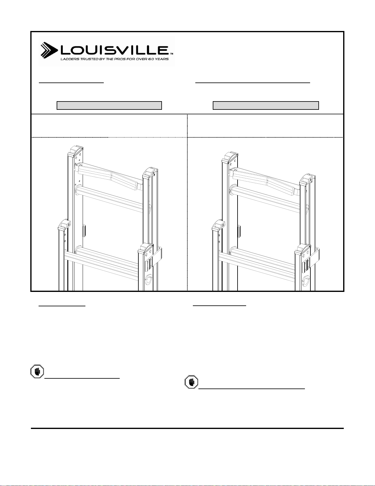
1) This accessory is designed to be installed only on extension ladders made of fiberglass manufactured by
Louisville Ladder only.
2) Read and follow instructions and labels on ladder carefully. All applicable safety procedures, such as
regional and local safety requirements, safe working practices, and good judgment must be used by all
persons involved in assembling and using ladders.
3) Do not modify this product. This product was designed to be assembled in the manner indicated in the
assembly instructions.
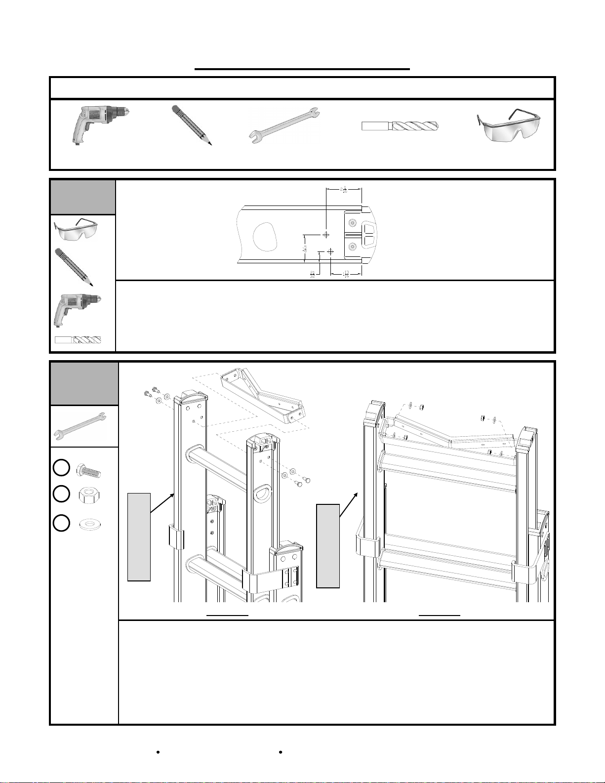
4) Safety glasses must be worn to prevent eye injury when drilling, or hacksaw cutting (Fig. 1).
5) Do not substitute hardware. This product is designed to be assembled with the hardware provided.
6) Make sure this kit fits your ladder. If you have any questions concerning the use of this kit on other
products, call 1-800-666-2811 for assistance.
7) Inspect the ladder before installing this kit. Repair or replace any damaged or missing parts before using
the ladder. Use only Louisville Ladder repair or replacement parts. If unable to repair, discard the ladder.
- Si no cumple con las siguientes advertencias o si modifica el producto de manera accidental
podría resultar en daños, lesiones graves o la muerte.
1) Este accesorio está diseñado para instalarse sólo en escaleras de extensión hechas de fibra de vidrio
fabricadas únicamente por Louisville Ladder.
2) Lea y siga las instrucciones y etiquetas de la escalera cuidadosamente. Todos los procedimientos de
seguridad aplicables, tales como requerimientos de seguridad locales o regionales, practicas seguras de
trabajo, y el buen juicio deberán ser empleadas por todas las personas involucradas en el ensamble y
uso de las escaleras.
3) No debe modificar este producto. El diseño de este producto exige que se arme de la manera indicada
en las instrucciones de armado.
4) Debe usar anteojos de protección para evitar lesiones oculares al taladrar, o cortar con segueta (Fig. 1)
5) No debe sustituir la tornillería. Se ha diseñado este producto de manera que exige que se arme con la
ferretería provista.
6) Asegúrese de que este kit le ajusta a su escalera. Si tiene preguntas concernientes al uso de este kit en
otros productos, llame al 1-800-666-2811 para asistencia.
7)Inspeccione la escalera antes de instalar este kit. Repare o reemplace cualquier parte dañada o faltante
antes de usar la escalera. Emplee únicamente partes de reparación o reemplazo de Louisville Ladder.
En caso de no poder reparar la escalera, deséchela.
Fig. 1
COMPONENTS
COMPONENTES
PK-E04A PK-E04B
Item Description Quantity Part Number Part Number
Artículo Descripción Cantidad Número de Parte Número de Parte
A Rigid Pole Grip | Sop. Rígido para Poste 1 315003B 315003C
B Reinforcement Bar/Barra de Refuerzo 1 316022K 316022M
A
B

1-800-666-2811 Toll Free Consumer Assistance Número Gratuito de Asistencia al Consumidor 3 of / de 6
Hardware Included
Tornillería Incluida
(4) Hex Bolt (ø1/4”-20x3/4”)
(4) Tornillo (ø1/4”-20x19.05mm)
F1881-63
(4) Locknut (ø1/4”-20)
(4) Tuerca de Seguridad (ø1/4”-20)
F1979-63
(8) Plain Washer (ø1/4”)
(8) Arandela Plana (ø1/4”)
F0289-63
1
Fig. A Fig. B
Fig. C
Verify your ladder type:
1. If you have a ladder with pre-pierced holes (Fig. A) on the
top fly section, please see Section A for Assembly
Instructions.
2. If you have a ladder without pre-pierced holes (Fig. B) on
the top fly section, or a Plate Connected one (Fig. C)
please see Section B for Assembly Instructions.
Verifique su tipo de escalera:
1. Si tiene una escalera con agujeros pre-punzonados (Fig. A)
en el extremo superior de la sección móvil de la misma,
favor de ver la Sección A para Instrucciones de Ensamble.
2. Si tiene una escalera sin agujeros pre-punzonados (Fig. B)
en el extremo superior de la sección móvil de la misma,
o una con Peldaño Remachado (Fig. C) favor de ver la
Sección B para Instrucciones de Ensamble.
H1
H2
H3

1-800-666-2811 Toll Free Consumer Assistance Número Gratuito de Asistencia al Consumidor 4 of / de 6
SECTION A // SECCION A
Tools Required
Herramientas Necesarias
(2) 7/16” Wrenches | (2) Llaves de 7/16”
A1
Fig. A1-1
Fig. A1-2 Fig. A1-3
x2
x4
x4
x8
1. Identify, on the top fly section rails, the two pre-
pierced holes highlighted in Fig. A1-1.
2. Place the RIGID POLE GRIP ASSEMBLY and the
REINFORCEMENT BAR as shown in Fig. A1-2
aligning them to the identified holes and fix them to
the ladder using (4) H3 washers and (4) H1 bolts.
3. Make sure that the accessory is oriented as shown
in Figs. A1-2 and A1-3.
4. Place (4) H3 washers and (4) H2 nuts as shown in
Fig. A1-2. Hand tight locknuts onto bolts.
5. Using the (2) 7/16” wrenches, tighten all bolts and
locknuts steadily.
1. Identifique, en el extremo superior de los largueros de la
sección móvil, los cuatro agujeros pre-punzonados
remarcados en la Fig. A1-1 con una línea mas gruesa.
2. Coloque el SOPORTE RÍGIDO PARA POSTE y la
BARRA DE REFUERZO como se muestra en la Fig. A1-
2alineándolos con los agujeros identificados y fíjelos a la
escalera empleando (4) arandelas H3 y (4) tornillos H1.
3. Asegúrese de que el accesorio queda orientado como se
muestra en la Figs. A1-2 y A1-3.
4. Coloque (8) arandelas H3 y (8) tuercas H2 como se
muestra en la Fig. A1-3. Apriételas un poco a mano.
5. Usando (2) llaves de 7/16” apriete todos los tornillos y
tuercas de seguridad firmemente.
FRONT OF LADDER
FRENTE DE ESCALERA
TOP OF FLY SECTION
EXTREMO SUP. SECCION MOVIL
FRONT OF LADDER
FRENTE DE ESCALERA
FRONT OF LADDER
FRENTE DE ESCALERA
H1
H2
H3

1-800-666-2811 Toll Free Consumer Assistance Número Gratuito de Asistencia al Consumidor 5 of / de 6
SECTION B // SECCION B
Tools Required
Herramientas Necesarias
Drill
Taladro
Pencil
Lápiz
(2) 7/16” Wrenches
(2) Llaves de 7/16”
(1) 1/4” Drill Bit
(1) Broca de 1/4”
Safety glasses
Lentes de seguridad
B1
x1
x1
x1
x1
1. To mount the RIGID POLE GRIP KIT, you must first
mark the hole locations on the fly section.
2. Measure and mark with a pencil the hole pattern.
Repeat for both rails.
3. Using a drill and 1/4” drill bit, drill the rails at the
marks just made.
1. Para montar el KIT DE SOPORTE RIGIDO, debe primero
marcar la ubicación de los agujeros en la sección móvil.
2. Mida y marque con un lápiz el patrón de agujeros. Repita
para ambos largueros
3. Usando un taladro y una broca de 1/4”, taladre los
largueros en las marcas que acaba de hacer.
B2
Fig. B2-1 Fig. B2-2
x2
x4
x4
x8
1. Place the RIGID POLE GRIP ASSEMBLY and the
REINFORCEMENT BAR as shown in Fig. B2-1
aligning them to the identified holes and fix them to
the ladder using (4) H3 washers and (4) H1 bolts.
2. Make sure that the accessory is oriented as shown
in Figs. B2-1 and B2-2.
3. Place (4) H3 washers and (4) H2 nuts as shown in
Fig. B2-2. Hand tight locknuts onto bolts.
4. Using the (2) 7/16” wrenches, tighten all bolts and
locknuts steadily.
1. Coloque el SOPORTE RÍGIDO PARA POSTE y la
BARRA DE REFUERZO como se muestra en la Fig.
B2-1 alineándolos con los agujeros identificados y
fíjelos a la escalera empleando (4) arandelas H3 y (4)
tornillos H1.
2. Asegúrese de que el accesorio queda orientado como
se muestra en la Figs. B2-1 y B2-2.
3. Coloque (8) arandelas H3 y (8) tuercas H2 como se
muestra en la Fig. B2-2. Apriételas un poco a mano.
4. Usando (2) llaves de 7/16” apriete todos los tornillos y
tuercas de seguridad firmemente.
LADDER RAIL / LARGUERO
H1
H2
H3
FRONT OF LADDER
FRENTE DE ESCALERA
FRONT OF LADDER
FRENTE DE ESCALERA

1-800-666-2811 Toll Free Consumer Assistance Número Gratuito de Asistencia al Consumidor 6 of / de 6
KIT PK-E04A CAN BE USED ON THE
FOLLOWING MODELS:
MODEL - SERIES
LADDER SIZE (XX)
534-XX
16’ –28’
578-XX
16’ – 28’
618-XX
16’ – 28’
71XX-2 L
20’ – 24’
CFGD12XX
16’ – 28’
CFG11XX
16’ – 28’
D-3121-XX
16’ – 20’
D59XX-2 L
28’
D62XX-2 L
24’ -32’
FE06XX
16’ – 28’
FE17XX
16’ – 28’
FE22XX
16’ – 28’
FE26XX
16’ – 28’
FE32XX
16’ – 28’
FE42XX
16’-28’
FE42XXHD
20’ – 28’
FE46XX
16’ – 28’
FE46XXHD
16’ – 28’
FE72XX
16’ – 28’
FE76XX
16’ – 28’
L-3022-XX
16’ – 40’
L-3121-XX
16’ – 28’
L-3221-XX
16’ – 28’
L-3221-XX-CAM
16’
R-3021-XX
08’ – 40’
R-3022-XX
40’
R-3121-XX
36’ – 40’
KIT PK-E04B CAN BE USED ON THE
FOLLOWING MODELS:
MODEL - SERIES
LADDER SIZE (XX)
534-XX
32’ – 40’
578-XX
32’
CFGD12XX
32’ – 40’
CFG11XX
32’ – 40’
FE22XX
32’ – 40’
FE26XX
32’–40’
FE22XX
32’–40’
FE72XX
32’–40’
FE76XX
32’-40’
KIT PK-E04A PUEDE SER USANDO EN LOS
SIGUIENTES MODELOS:
MODELO - SERIES
TAMAÑO ESCALERA (XX)
534-XX
16’ –28’
578-XX
16’ – 28’
618-XX
16’ – 28’
71XX-2 L
20’ – 24’
CFGD12XX
16’ – 28’
CFG11XX
16’ – 28’
D-3121-XX
16’ – 20’
D59XX-2 L
28’
D62XX-2 L
24’ -32’
FE06XX
16’ – 28’
FE17XX
16’ – 28’
FE22XX
16’ – 28’
FE26XX
16’ – 28’
FE32XX
16’ – 28’
FE42XX
16’-28’
FE42XXHD
20’ – 28’
FE46XX
16’ – 28’
FE46XXHD
16’ – 28’
FE72XX
16’ – 28’
FE76XX
16’ – 28’
L-3022-XX
16’ – 40’
L-3121-XX
16’ – 28’
L-3221-XX
16’ – 28’
L-3221-XX-CAM
16’
R-3021-XX
08’ – 40’
R-3022-XX
40’
R-3121-XX
36’ – 40’
KIT PK-E04B PUEDE SER USADO EN LOS
SIGUIENTES MODELOS:
MODELO - SERIES
TAMAÑO ESCALERA (XX)
534-XX
32’ – 40’
578-XX
32’
CFGD12XX
32’ – 40’
CFG11XX
32’ – 40’
FE22XX
32’ – 40’
FE26XX
32’–40’
FE22XX
32’–40’
FE72XX
32’–40’
FE76XX
32’-40’
Table of contents
Other Louisville Ladder manuals
Popular Ladder manuals by other brands

LADDERSTORE
LADDERSTORE LADDERFIX MICROLITE Instruction leaflet

Canbuilt
Canbuilt NH Series Assembly and user's guide

Cotterman
Cotterman 6500 Series Assembly

TOOLCRAFT
TOOLCRAFT 2622938 operating instructions

GIERRE
GIERRE PEPPina AM100 Operating and maintenance instructions

Powerfix Profi
Powerfix Profi HG01613 Operation and safety notes