Louisville PINNACLE Series User manual

ATTIC LADDER
INSTALLATION
INSTRUCTIONS
INSTRUCCIONES DE INSTALACIÓN DE LA ESCALERA DE ÁTICO
PINNACLE SERIES
MODELS/MODELOS: AEE3010 | AEE2510 | AEE2210
English: Page 1 / Spanish: Page 12 |Inglés: Página 1 / Español: Página 12

WARNING
Before you start installing your new Louisville Ceiling Mounted Folding Attic Ladder, you
must read and understand the following:
1. For residential use only. Not for use in a commercial or industrial setting.
2. Installation requires two people.
3. Do NOT remove plastic straps holding the ladder sections together until instructed
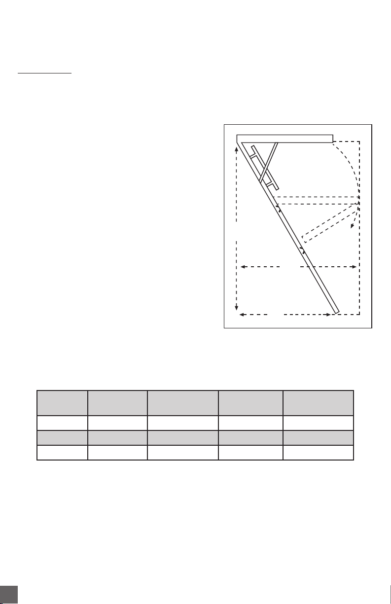
4. Check the ceiling height to make sure the ladder length is correct. If the ladder is too short,
return it to the point of purchase for an exchange. Under no circumstance is any folding attic ladder
to be used when the ceiling-to-floor measurement exceeds the maximum ceiling height as indicated
for the Ceiling Mounted Folding Attic Ladder you are installing (See “Ceiling Height Range”column in
table 1)
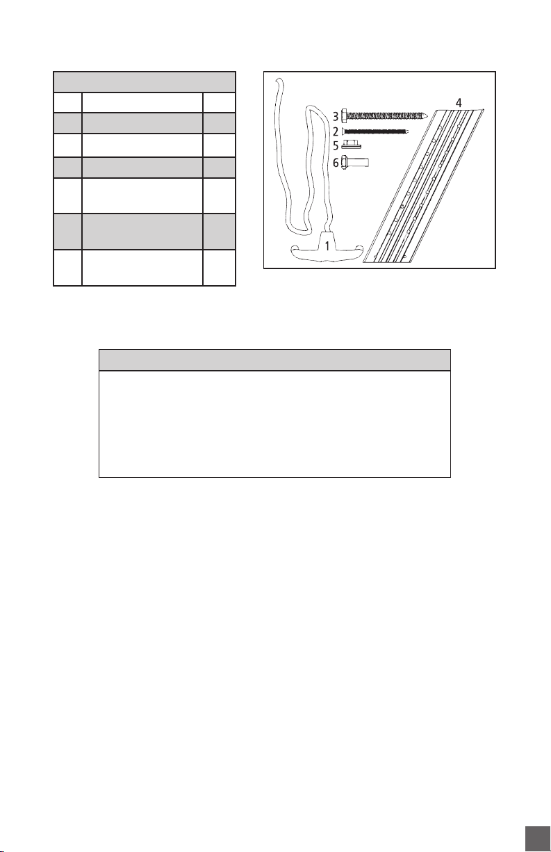
5. This folding attic ladder is completely assembled and is ready for installation.
Do not disassemble it to install.
6. The springs/gas cylinders on this folding attic ladder are under pressure. Do not attempt to remove or
replace before installation.
7. Prior to installation, verify that all fasteners are properly tightened. Re-check these periodically after
initial installation.
8. Make sure there is no wiring or piping that the saw or drill can come in contact with during installation.
9. Opening or standing on the folding attic ladder’s climbing sections prior to properly fastening to ceiling
joists could cause serious bodily injury.
10. Verify that the unit meets local building codes and that the intended area of installation is of sufficient
strength to be used for a walking or working surface.
11. If the home has roof trusses, do not cut the ceiling joists without consulting an engineer for approval.
12. Before installation, read all the instruction labels on the folding attic ladder.
13. Improper installation could result in serious bodily injury.
14. Do not attempt to open the door prior to installation.
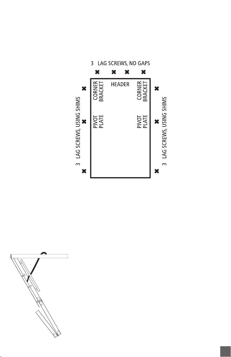
15. Only use the lag screws provided for the permanent installation step.
16. Follow the “Adjust The Ladder Height”instructions on Step 3 for proper trimming instructions.
17. Annually lubricate (spray silicon recommended) pivot points of right and left folding arm mechanism
(power arm assembly) to provide smooth, long-lasting operation.
1

Included with your Folding Attic Ladder:
ALUMINUM SERIES
NO. ITEM QTY
1Pull cord 36”1
2Deck screw 2 ½”8
3Lag screw 3”10
4Aluminum Feet
(mounted on ladder) 2
5¼”Nuts
(mounted on ladder) 4
6Bolts ¼”x ¾”large
(mounted on ladder) 4FIGURE 1: Aluminum series
MATERIALS REQUIRED
1. Stepladder 6. Drill
2. Hammer 7. Drill bit ⁄”
3. Adjustable wrench 8. Phillips screw driver
4. Tape measure 9. (2) Temporary boards 1” x 4” x 34”
5. Hack saw 10. Shims
2

INSTALLATION INSTRUCTIONS
READ INSTRUCTIONS AND WARNINGS COMPLETELY BEFORE STARTING
IMPORTANT: Do not open folding attic ladder until instructed to in
step number 3.
FOLDING ATTIC LADDER LOCATION:
Allow ample room for the swing clearance and
the landing space of the folding attic ladder when
it is opened (see Figure 2 and table 1). Locate the
folding attic ladder rough opening so that when
you enter the storage area, you will have adequate
head clearance.
You must have a rough opening as shown for your
model on table 1. If not, proceed to the appendix
for framing instructions.
MODEL
ROUGH
OPENING
CEILING HT.
RANGE “A”
LANDING
SPACE “B”
SWING
CLEARANCE “C”
AEE3010 30”x 54”7’7” – 10’3” 69”74”
AEE2510 25 ½”x 54”7’7” – 10’3” 69”74”
AEE2210 22 ½”x 54”7’7” – 10’3” 69”74”
TABLE 1
B
LANDING SPACE
C
SWING CLEARANCE
A
CEILING
HEIGHT
RANGE
FIGURE 2
3

STEP 1: PRELIMINARY INSTALLATION INSTRUCTIONS
A. Attach temporary supports “A”and “B”with 2 ½”deck screws as shown in Figure 3.
Support “A”should be located at the end where the door hinge of the ladder will go. The
edge of support “A”should extend into the rough opening ⁄”as shown in Figure 4. Make
sure both screws penetrate header above ceiling.
B. Measuring from the inside edge of support “A”, locate and secure the inside edge of support
“B”52 ¾”from inside edge of support “A”(Figure 4). Make sure both screws penetrate
header above ceiling.
C. Thread pull cord through pre-drilled hole in door and tie a knot in end of cord. Length can
be adjusted after ladder is completely installed. Be sure the knot is large enough to not slip
through the hole.
Remove aluminum feet on bottom section. These will be reinstalled in Step 3.
D. Position one person up in the attic, and position the other person in the room below. When
using stepladder make sure ladder is fully open, all feet firmly supported and user’s weight
and materials he is carrying does not exceed the load rating of the ladder.
Deck screw (2) per board
FIGURE 3: View from below
Support “A”Support “B”
FIGURE 4: View from above
Support “B”
Support “A”
⁄”52 ¾”
4

FIGURE 5
Support “A”
Support “B”
E. The person below will need to raise the attic ladder into the rough opening and with
assistance from person above position securely on the temporary support boards (Figure 5).
F. Make sure frame on door hinge side of ladder is pushed up against header and is centered
side to side in rough opening. Temporarily secure frame to header using two 2 ½”deck
screws (Figure 6). Do not use pre-drilled holes for deck screws. Pre-drilled holes are used in
Step 2.
CAUTION: This is only a temporary connection, NEVER climb on ladder in this condition.
G. Carefully open attic ladder door but do not unfold the climbing section until indicated in
step 3. Center and square the opposite side of attic ladder frame in the rough opening using
shims. Ensure ladder frame is square by measuring diagonals of the frame within ⁄”
(Figure 6).
CAUTION: Failure to properly square frame will result in door not closing.
Make sure diagonal measurements are equal within 1/8”
H. Secure sides of ladder frame to ceiling joists with 2 ½”deck screws at shim locations
(Figure 6). Do not use pre-drilled holes for deck screws. Pre-drilled holes are used in Step 2.
Door hinge end
Shim
Header
Frame
Rough opening
FIGURE 6
D1
D2
D1 & D2
should be
EQUAL
5

STEP 2: PERMANENT INSTALLATION
A. The ladder comes with pre-drilled holes for permanent installation at locations shown in
Figure 7. Shim, when necessary to fill space between ladder frame and rough opening, at
pre-drilled locations. Using ⁄”drill bit, drill pilot holes through shim into ceiling joists and
header.
B. Install the ten 3”lag screws provided, at each location to permanently secure the ladder.
C. WARNING: Never use deck or sheetrock screws in place of lag screws for
permanent installation.
D. Remove temporary boards from ceiling installed in step 1.
STEP 3: ADJUST LADDER LENGTH
Remove plastic straps holding the sections together and carefully
unfold ladder to the ground rotating bottom section behind
middle section (Figure 8).
FIGURE 8
FIGURE 7
”
”
”
6

CEILING HEIGHT RAIL CUT FOOT CUT
7’7”– 7’8”* Figure 9, step #3 E
7’9”– 7’10”C E
7’11”– 8’2”C D
8’3”– 8’5”C no cut
8’6”Figure 9, step #2 no cut
8’7”– 9’1”B no cut
9’2”– 9’3”A no cut
9’4”– 9’9”Figure 9, step #1 no cut
9’10”– 10’3”no cut no cut
TABLE 3
*7’7”to 7’8”ceiling
heights require
drilling mounting
holes. Use foot as
drilling template.
Bottom section side rail
FIGURE 9
Aluminum feet
D E
STEP 3:
Cut not marked
on rail
STEP 2:
Cut not marked
on rail
STEP 1:
Cut not marked
on rail
C B A
ALUMINUM MODELS ONLY:
A. Using a tape measure double check the height of the ceiling.
B. Determine the location to cut the ladder and ladder feet for your ceiling height from table 3.
C. Cut the side rails and ladder feet (when required) at the appropriate line.
NOTE: The rail is not pre-marked for angle cuts required below a step (see Figure 9).
D. Press down on the climbing section to ensure that the folding arms are fully extended.
7

FIGURE 11 FIGURE 12 FIGURE 13
Gap No gap
Feet flush
with floor Feet ARE NOT
flush with floor
GapNo gap
FIGURE 10
E. Slide aluminum foot over ladder rail as shown in
Figure 10. Position so the rubber foot is in contact
with the floor.Align with closest set of predrilled
holes in rail. Attach using (2) ¼”bolts and
serrated nuts per side (included).
Check the length after making your cuts
Again, be sure the attic ladder power arms are fully extended. Trimmed correctly, your attic
ladder should look like Figure 12.Verify that there are no gaps in the section and both feet are
flat on the floor.
If the attic ladder looks like Figure 13, then both of the legs are too long. To shorten, remove
bolts from adjustable foot, slide up to the next set of holes, and reinstall nuts and bolts.
If the attic ladder looks like Figure 11, then both of the legs are too short. To lengthen, remove
bolts from adjustable foot, extend to next set of holes, and reinstall nuts and bolts
To install trim molding leave ⁄”clearance between your door panel at the hinged end and ⁄”
on other 3 sides.
For customer service, call Louisville Ladder at
1-800-666-2811 or e-mail info@louisvilleladder.com.
8

APPENDIX - Framing A Rough Opening Parallel To Ceiling Joist
Make a rough opening to the size as required in table 1 ensuring that the dimensions of the
diagonals of the frame are the same as illustrated in Figure 14.
A. For Rough opening without joist removal (Figure 14)
• Locate headers in front and rear of the
opening as shown in Figure 14.
• Check for squareness by making sure
that diagonal measurements are
within ⁄”.
• Secure using (3) 16d nails into each end
of the Header.
B. Rough opening with joist removal (Figure 15)
• Install temporary support boards
spanning both sides of joists to
be removed.
• Remove joist at length to allow for
double headers to be installed on both
ends of opening.
Continued on next page...
FIGURE 14
Header
Header
54”
Diagonal
Measurements
Nails
FIGURE 15
Temporary Support
Boards
MODEL
ROUGH
OPENING
CEILING HT.
RANGE “A”
LANDING
SPACE “B”
SWING
CLEARANCE “C”
AEE3010 30”x 54”7’7” – 10’3” 69”74”
AEE2510 25 ½”x 54”7’7” – 10’3” 69”74”
AEE2210 22 ½”x 54”7’7” – 10’3” 69”74”
TABLE 1 (Repeated from page 3)
9

(Figure 16)
• Locate double headers at each end of
opening and secure with (3) 16d nails
into each end of the headers.
• Install stringer and check for squareness
by making sure that diagonals are
within ⁄”.
• Secure using (3) 4”nails into each end
of the stringer.
CAUTION: Consult an engineer
or obtain architectural approval
for installations that require the
removal of roof trusses or rough
openings perpendicular to the
ceiling joists.
FIGURE 16
Headers
Headers
Nails
Diagonal
Measurements
Stringer
Customer service: 1-800-666-2811 or e-mail info@louisvilleladder.com
10

11

ADVERTENCIA
Antes de empezar la instalación de su nueva escalera de ático plegable para montaje en el techo
Louisville, debe leer y entender lo siguiente:
1. Solo para uso residencial, no para uso de establecimientos comerciales o industriales.
2. La instalación requiere 2 personas
3. Favor de NO remover los cinchos de plástico que aseguran las secciones de la
escalera hasta que se indique.
4. Revise que la altura del techo no sea mayor que el largo de la escalera. Si la escalera es muy corta,
regrésela al punto de venta y cámbiela. Bajo ninguna circunstancia la escalera de ático plegable se usará cuando
la medida del techo al suelo exceda la máxima altura permitida como se indica en la escalera que está instalando
(Véase la columna de rango de altura de techo en la Tabla 1)
5. La escalera de ático plegable se encuentra completamente ensamblada y lista para instalación. Favor de no
desensamblar para instalar
6. Los pistones de gas / resortes ubicados en la escalera de ático plegable se encuentran bajo presión, por ninguna
circunstancia remueva o remplace antes de la instalación.
7. Antes de instalación, confirme que todos los componentes de ensamble se encuentren apretados. Revise
periódicamente después de la instalación.
8.Asegúrese que no haya cables o tuberías con los que la sierra o el taladro puedan tener contacto durante la instalación.
9. No abra o pise en la secciones de la escalera de ático plegable antes de estar apropiadamente sujetas a las vigas
del techo, ya que hacerlo podría causar serias lesiones corporales.
10. Asegúrese de que la unidad cumpla con los códigos locales de construcción y que la zona prevista para la
instalación la escalera cuente con la suficiente fortaleza para ser utilizada como área de transito o de trabajo.
11. Si la casa tiene vigas, no las corte sin antes consultar a un ingeniero para su aprobación.
12. Antes de la instalación, lea todas las etiquetas en la escalera de ático plegable.
13. La instalación inapropiada de la escalera puede causar serias heridas.
14. No intente abrir la puerta antes de ser instalada.
15. Para la instalación de la escalera use las pijas de cabeza hexagonal provistos para la etapa de instalación permanente.
16. Siga las instrucciones “AJUSTE EL LARGO DE LA ESCALERA”en el paso 3 para las instrucciones adecuadas de corte.
17. Lubrique anualmente las bisagras izquierda y derecha del brazo mecánico plegable (brazo de poder) para
proporcionar una suave, larga y duradera operación. Se recomienda silicón en spray.
12

Componentes Incluidos en la Escalera de ático plegable para montaje en el techo:
SERIE DE ALUMINIO
NO. ARTICULO CANTIDAD
1Cordón 36”1
2Pija de madera 2 ½”8
3Pija hexagonal 3”10
4Base aluminio
(montadas en escalera) 2
5Tuercas de un ¼”
(montadas en escalera) 4
6Tornillos de ¼”x ¾”
(montadas en escalera) 4
FIGURA 1: Serie de Aluminio
MATERIALES NECESARIOS
1. Escalera de tijera 6. Taladro
2. Martillo 7. Broca de ⁄”
3. Una llave ⁄”8. Destornillador de estrella
4. Cinta de medir 9. (2) placas de apoyo 1” x 4” x 34”
5. Sierra caladora 10. Calzas
13

INSTRUCCIONES DE INSTALACIÓN
Lea las instrucciones y advertencias completas antes de empezar
IMPORTANTE: No abra la escalera de ático plegable hasta que se indique en el paso 3
UBICACIÓN DE ESCALERA PLEGABLE DE ÁTICO:
Deje espacio suficientemente amplio para la apertura y descenso
de la escalera plegable de ático cuando sea abierta (véalo en
la Figura 2 y en la Tabla 1). Ubique la apertura en el techo de
manera que cuando entre en el área de almacenamiento tenga
un espacio adecuado.
Usted debe tener una abertura aproximada de 22 ½”x 54”o
25 ½”x 54”según el modelo de la escalera. Si no lo tiene,
diríjase al Anexo para instrucciones de encuadre.
MODELO
APERTURA
APROXIMADA
“A”RANGO DE
ALTURA DEL TECHO
“B”DISTANCIA
DE APERTURA
“C”ESPACIO
PARA DESPLIEGUE
AEE3010 30”x 54”7’7” – 10’3” 69”74”
AEE2510 25 ½”x 54”7’7” – 10’3” 69”74”
AEE2210 22 ½”x 54”7’7” – 10’3” 69”74”
TABLA 1
B
DISTANCIA DE APERTURA
C
ESPACIO PARA
DESPLIEGUE
ARANGO DE
ALTURA DEL
TECHO
FIGURA 2
14

PASO 1: INSTRUCCIONES DE INSTALACIÓN PRELIMINARES
A. Añada soportes temporales “A”y “B”con pijas de 2 ½”como se muestra en la Figura 3. El soporte
“A”debe estar situado en el extremo, donde se ubica la bisagra de la puerta de la escalera. El
borde del soporte “A”deberá extenderse ⁄”dentro de la abertura como se muestra en la Figura 4.
Asegúrese de que ambas pijas penetren el cabezal por encima del techo.
B. Mida desde el borde interior del soporte “A”, posicione y asegure el borde interior del soporte “B”
a 52 ¾”(Figura 4). Asegúrese de que ambas pijas penetren el cabezal por encima del techo.
C. Inserte el cordón sujetador a través del orificio pre-perforado en la puerta y forme un nudo en el
extremo del cordón. La longitud puede ajustarse después de que la escalera esté completamente
instalada. Asegúrese de que el nudo es lo suficientemente grande como para no caber por el agujero.
Remueva los tacones de aluminio de la sección inferior, éstos serán re-instalados en el
Paso 3.
D. Posicione una persona en el ático, y la otra persona en la habitación de abajo. Cuando utilice la
escalera de tijera asegúrese que esté completamente abierta, todos los tacones firmemente
apoyados, y que el peso del usuario y los materiales que se transportan no exceda la capacidad de
carga de la escalera.
Pijas de madera de 2 por soporte temporal
FIGURA 3
Soporte “A”Soporte “B”
FIGURA 4: Vista desde arriba
Soporte “A”
Soporte “B”
⁄”52 ¾”
15

E. La persona que este abajo, tendrá que levantar la escalera de ático hacia la abertura del techo y deberá
ser asistido por la persona en el ático, asegurando la escalera sobre los soportes temporales (Figura 5)
F. Asegúrese que el marco en el lado de la bisagra de la escalera este presionado contra el cabezal y
que este centrado de lado a lado en la abertura del techo; Asegure temporalmente el marco al cabezal
usando pijas de 2 ½”(Figura 6). No use los agujeros pre-perforados. Los agujeros pre-perforados serán
usados en el Paso 2.
PRECAUCIÓN: Esto es solo una instalación temporal, NUNCA suba a la escalera en esta condición.
G. Abra cuidadosamente la puerta de la escalera de ático pero sin desdoblar la sección para escalar
hasta que se indique en el paso 3. Centre y cuadre el lado opuesto del marco de la escalera de ático
en la abertura del techo utilizando cuñas. Asegúrese que el marco de la escalera haya sido cuadrado
correctamente tomando dimensiones diagonales en el marco hasta con ⁄”de diferencia entre ellas.
(Figura 6).
PRECAUCIÓN: No adecuar el encuadre del marco correctamente puede
resultar que la puerta no cierre. Asegúrese de que las medidas diagonales
sean iguales a 1/8”
H. Asegure los costados del marco a las vigas del techo con pijas de 2 ½”en la posición de las cuñas
(Figura 6). No utilice los agujeros pre-perforados para las pijas. Agujeros pre-perforados se serán
usados en el Paso 2.
Extremo de bisagra para puerta
Cuña
Cabezal
Marco
Abertura del techo
FIGURA 6
FIGURA 5
Soporte “A”
Soporte “B”
D1
D2
D1 y D2
deben tener
la misma
distancia
16

PASO 2: INSTALACION PERMANENTE
A. La escalera viene con agujeros pre-perforados para instalación permanente, los agujeros para la
instalación permanente se muestran en la Figura 7. Use cuñas cuando sea necesario para llenar el
espacio entre el marco de la escalera y abertura en el techo, en lugares pre-perforados. Usando la broca
de ⁄”, perfore orificios guía a través de cuña hasta las vigas del techo y el cabezal.
B. Instale las diez pijas hexagonales de 3”incluidas, en cada lugar para asegurar permanentemente la escalera.
C. ADVERTENCIA: Nunca use pijas de madera o tablaroca en lugar de las pijas hexagonales
para la instalación permanente.
D. Remueva los soportes temporales del techo instalados en el paso 1.
PASO 3: AJUSTE EL LARGO DE LA ESCALERA
Remueva los cinchos de plástico que sujetan las secciones entre sí y desdoble cuidadosamente la escalera
extendiéndola al suelo girando la sección inferior detrás de la sección media (Figura 8).
FIGURA 8
FIGURA 7
”
”
”
17

A. Use una cinta de medir para corroborar la altura del techo.
B. Determine la ubicación de corte de la escalera y de los tacones dependiendo de la altura de su techo
en la Tabla 3.
C. Corte los rieles laterales y los tacones de escalera (cuando se requiera) en la línea apropiada.
NOTA: el riel no está pre-marcado para los ángulos de corte requeridos por debajo del peldaño.
(véase la Figura 9).
D. Presione las secciónes para asegurar que los brazos plegadizos estén completamente extendidos.
ALTURA DEL TECHO CORTE DEL RIEL CORTE DEL TACÓN
7’7”– 7’8”* Figura 9, peldaño #3 E
7’ 9” – 7’ 10” C E
7’ 11” – 8’ 2” C D
8’ 3” – 8’ 5” C sin corte
8’ 6” Figura 9, peldaño #2 sin corte
8’ 7” – 9’ 1” B sin corte
9’ 2” – 9’ 3” A sin corte
9’ 4” – 9’ 9” Figura 9, peldaño #1 sin corte
9’ 10” – 10’ 2” sin corte sin corte
TABLA 3
*Las alturas del
techo de 7’7”a
7’8”requieren de
agujeros de montaje.
Utilice los tacones
como plantilla de
perforación.
Sección inferior del riel lateral
FIGURA 9
Tacón de aluminio
D E
PELDAÑO 3:
Corte no marcado
en el riel
PELDAÑO 2:
Corte no marcado
en el riel
PELDAÑO 1:
Corte no marcado
en el riel
C B A
18

E. Deslice el tacón de aluminio sobre el riel como se
muestra en la Figura 10. Posiciónelo de modo que el
tacón plástico esté en contacto con el suelo. Alinee el
más cercano conjunto de agujeros con los agujeros
perforados en el riel. Sujételo usando (2) tornillos de
¼” y tuercas dentadas por cada lado (incluidas).
Revise las longitudes después de marcar los cortes
De nuevo, asegúrese que los brazos de poder de la escalera de ático estén totalmente extendidos.
Una vez cortados correctamente, su escalera de ático debe verse como en la Figura 12. No debe haber
espacios entre las secciones y ambos tacones deben estar planos en el suelo como resultado.
Si los largueros se ven como la figura 13, estan muy largos. Para ajustarlos, quite los tornillos y tuercas de
los tacones ajustables y deslice hacia arriba para acomodar a la altura ideal, una vez definida la altura,
volver a ajustar con los tornillos y tuercas.
Si los largueros se ven como la figura 11, estan muy cortos. Para ajustarlos, quite los tornillos y tuercas de
los tacones ajustables y deslice hacia abajo para acomodar a la altura ideal, una vez definida la altura,
volver a ajustar con los tornillos y tuercas.
Para servicio al cliente, llame a Louisville Ladder al 1-800-666-2811
o por correo electrónico info@louisvilleladder.com
FIGURA 10
FIGURA 11 FIGURA 12 FIGURA 13
Espacio No espacio
Pie al ras
del suelo Pie no al
ras del suelo
Espacio
No
espacio
19
This manual suits for next models
3
Table of contents
Languages:
Other Louisville Ladder manuals
Popular Ladder manuals by other brands

Clarke
Clarke TL-2C Operation & maintenance instructions

PRIMAL TREESTANDS
PRIMAL TREESTANDS PVLS-316 Instruction and safety manual

Powerfix Profi
Powerfix Profi HG01091 Assembly, operating and safety instructions

Youngman
Youngman Adjusta-Minit user guide

VIEWRAIL
VIEWRAIL Straight Stringer installation guide

Equinox Systems
Equinox Systems B40.038 installation instructions