Step 4
Remove the radiator cap to allow the
coolant to drain faster. Inspect the cap
and replace if needed.
Note: Click HERE to see what Low
Range has to offer.
Step 5
Let the coolant drain until it stops
coming out.
Note: Green coolant can be reused if it
is less than 2 yrs. old and clean. If it is
too old or dirty it should be replaced. Be
sure to dispose of old fluid in
accordance with local, state and federal
laws.
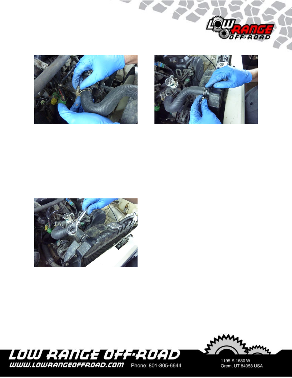
Step 6
Loosen the hose clamp using a 10 mm
socket.
Tech Tip 6
These hose clamps are removed using
a screwdriver or a socket. It is best to
thread the screw all the way loose as is
shown here. Inspect the clamp and
replace if needed. Click HERE to see
what Low Range has to offer.
Upper Radiator Hose Removal