.
Human Machine Interface Installation Guide
LXP-MxxD
This installationguide providessimple functioninformationof HMI control. Please read carefully
this data sheet and manuals before using products. Especially read safety precautions and
handle the products properly.
■Meaning of warning and caution inscription
WARNING indicates a potentially hazardous situation which,
if not avoided, could result in death or serious injury
CAUTION indicates a potentially hazardous situation which,
if not avoided, may result in minor or moderate injury.
It may also be used to alert against unsafe practices
①Do not contact the terminals while the power is applied.
②Protect the product from being gone into by foreign metallic matter.
③
Do not manipulate the battery.(Charge, disassemble, hitting, short, soldering)
①Be sure to check the rated voltage and terminal arrangement before wiring.
②When wiring, tighten the screw of terminal block with the specified torque rage.
③Do not install the flammable things on surroundings.
④Do not use the HMI in the environment of direct vibration.
⑤Except expert A/S staff, Do not disassemble or fix or modify the product.
⑥Use the HMI in an environment that meets the general specifications contained
in this datasheet.
⑦Be sure that external load does not exceed the rating of output module.
⑧
When disposing of HMI and battery, treat it as industrial waste.
■To install, observe the below conditions.
∼
∼
∼
∼
5 Vibration
Resistance
IEC 61131-2
≤
㎐
in each
for
X, Y, Z
≤
㎐
■For system configuration, the following version is necessary.
1) XP-Runtime/LXP-Designer: V1.0 above
■Check the battery attached in the XGT Panel.
1) Use : Reserve backup data and RTC when power off
2) Standard : CR2032
■Check the accessories included in the box.
1) Display fixing bolts: 1 set (4ea)
2) DIN Rail bracket: 1set (includes 2bolts) ※Included when XP-VLink supported modules.
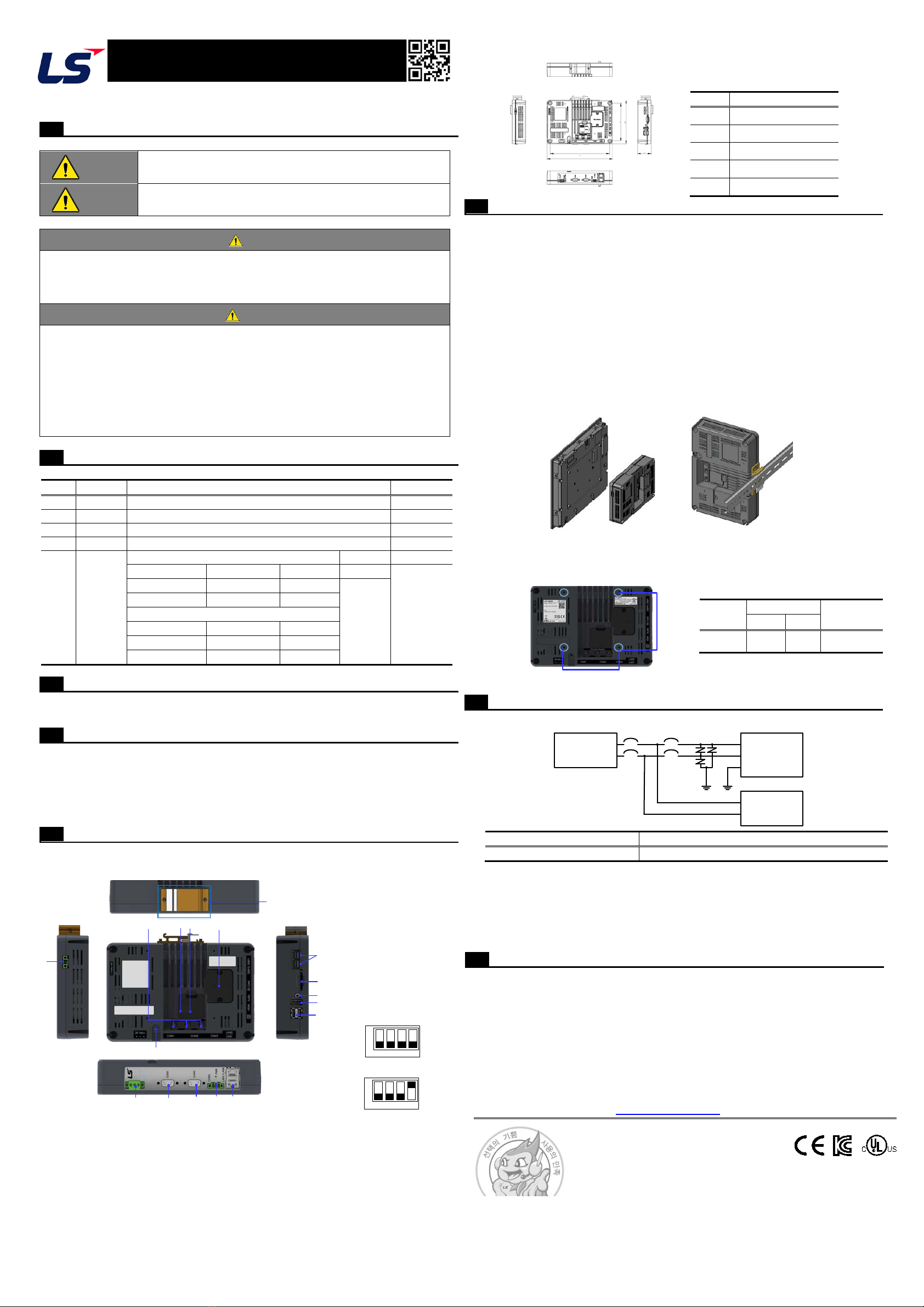
■This is appearance of the LXP. Refer to each name when driving the system. For more
information, refer to user manual.
■Dimension
■Precautions when installing the product be specified and allowed for.
1) Install and remove the product after turning off the power.
2) Apply power after installation of the product is complete.
■When installing the product on the display unit, please follow the standards below.
1) Be sure to remove DISP 0, 1 and power cables.
2) Fix firmly with the included fixing bolts.
■When installing the product on a DIN rail, please install it according to the standards
below.
1) The DIN rail size that can be installed is 35 mm.
2) Since there is a risk of DIN rail deformation, add a set screw to the product installation
location.
3) When installing the product, install the DIN rail bracket with the power connector facing
upward.
4) When installing, insert the hook on the top of the bracket into the DIN rail and press
down to install it.
5) After installation, use a DIN rail stopper to fix the product.
6) When disassembling, lift the product upwards and remove the top hook of the bracket
first. Panel Cut Dimensions
<Display unit installation> <DIN rail installation>
■When installing the product on the VESA mount, follow the standards below.
1) Use M4 bolts.
2) Use spacers if necessary.
■When installing the expansion memory, install it according to the standards below.
■Power wiring
1) Separate the power of the HMI from other devices (high voltage, high current devices)
and the system power. Also, keep the communication cable 100mm or more away
from the power cable.
2) Use the power and ground wiring within the range of 18AWG to 22AWG.
3) For grounding, use 3 types of grounding (ground resistance less than 100Ω), and it is
recommended to use a grounding wire of 2㎟or more. However, in case of
malfunction due to grounding, separate the grounding.
■Warranty period
LS ELECTRIC provides an 18-month-warranty from the date of the production.
■Scope of Warranty
1) The troubles caused by improper condition, environment or treatment except the
instructions of LS ELECTRIC.
2) The troubles caused by external devices.
3) The troubles caused by remodeling or repairing based on the user’s own discretion.
4) The troubles caused by improper usage of the product.
5) The troubles caused by the reason which exceeded the expectation from science and
technology level when LS ELECTRIC manufactured the product.
6) The troubles caused by natural disaster.
LS ELECTRIC Co., Ltd www.ls-electric.com 10310001842, V1.1 (2022.07)
•E-mail: automation@ls-electric.com
•Headquarter/Seoul Office
Tel: 82-2-2034-4033,4888,4703
•LS ELECTRIC Shanghai Office (China)
•LS ELECTRIC (Wuxi) Co., Ltd. (Wuxi, China)
•LS-ELECTRIC Vietnam Co., Ltd. (Hanoi, Vietnam)
•LS ELECTRIC Middle East FZE (Dubai, U.A.E.)
•LS ELECTRIC Europe B.V. (Hoofddorf, Netherlands)
•LS ELECTRIC Japan Co., Ltd. (Tokyo, Japan)
•LS ELECTRIC America Inc. (Chicago, USA)
•Factory: 56, Samseong 4-gil, Mokcheon-eup, Dongnam-gu, Cheonan-si, Chungcheongnam-
do, 31226, Korea
Parts name and Dimension(mm)
3Terminating resistance switch
4Expansion memory (option)
12 DIN Rail bracket (option)
Item
Screw
VESA 100 100 M4
Rated voltage DC24V
Power
supply XGT
Panel
Other
devices
Default value
User set value
※No. 4 switch is battery
ON/OFF
12
34
5
67
8
9
10
11
12
13 14 15 16 17
POWER
24Vd.c
10310001842