LS RS485/Modbus-RTU User manual


Thank you for purchasing LS RS485/Modbus-RTU Option Card!
SAFETY PRECAUTIONS
zAlways follow safety precautions to prevent accidents and potential hazards from occurring.
zIn this manual, safety messages are classified as follows:
WARNING Improper operation may result in serious personal injury or death.
Improper operation may result in slight to medium personal injury
or property damage.
CAUTION
zThroughout this manual we use the following two illustrations to make you aware of safety
considerations:
Identifies potential hazards under certain conditions
Read the message and follow the instructions carefully.
Identifies shock hazards under certain conditions
Particular attention should be directed because dangerous voltage may be present.
zKeep operating instructions handy for quick reference.
zRead this manual carefully to maximize the performance of SV-iP5A series inverter and ensure its
safe use.
CAUTION
zDo not touch the CMOS components unless the board is grounded.
Otherwise, ESD could cause break down of CMOS components.
zDo not change the communication cable when the inverter power is turned on.
Otherwise, there is a danger of connecting error and damage to the board.
zMake sure to precisely insert the connector of inverter and option board
Otherwise, there is a danger of connecting error and damage to the board.
zCheck the parameter unit when setting the parameters.
Otherwise, there is a danger of connecting error and damage to the board.
1

2
1. INTRODUCTION
1.1. Features
1.2.
2.
2.1.
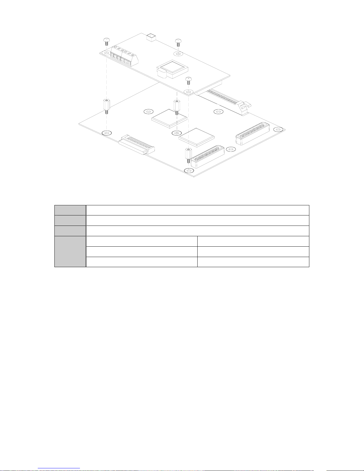
SV-iP5A/iV5 inverter can be controlled and monitored by the sequence program of the PLC or other
master module. The option card provides a terminal block for an RS-485/Modbus-RTU interface. Drives or
other slave devices may be connected in a multi-drop fashion on the RS-485/Modbus-RTU network and
may be monitored or controlled by a single PLC or PC.
Inverter can be easily applicable to Factory Automation because operation and monitoring is available by
User-program.
* Parameter setting and monitoring is available via computer.
(Ex: Freq. Command, Run/Stop etc.)
* Interface type of RS485 reference:
1) Allows the drive to communicate with any other computers.
2) Allows one computer to control up to 31 drives with multi-drop link system.
3) Noise-resistant interface.
Users can use any kind of RS232/485 converters. The specifications and performances of converters
depend on the manufacturers, but the basic functions are the same. Refer to the converter manual for
detailed specifications and instructions on how to use.
Before Installation
Before installation and operation, this manual should be read thoroughly. If not, it could cause personal
injury or damage other equipment.
SPECIFICATION
Performance specification
Items Specifications
Communication method RS485 (RS232/485 converter)
Transmission form Bus method, Multi-drop Link System
Applicable inverter SV-iP5A/iV5 series
Converter Converter with RS232 card embedded
Number of inverters connected Maximum 31 drives connectable note1)
Transmission distance Max. 1200m (Less than 700m recommended) note2)
note1) The number of inverters to be connected is up to 31.
note2) The specification of length of the communication cable is max. 1200m. To ensure stable
communication, limit its length below 700m.
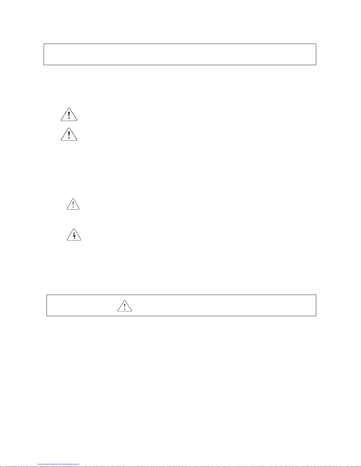
2.2. Hardware Specifications
Items Specifications
Installation Use option connector on the inverter control board
Control B/D From inverter power supply
Power Supply
Comm. B/D From control board (insulated)

3
2.3. Communication Specification
Items Specifications
Communication speed 1200 /2400/4800/9600/19200/38400 bps Selectable
Control procedure Asynchronous communication system
Communication system Half duplex system
Character system RS485 : ASCII(8bit), Modbus-RTU : Binary (7/8 bit)
Start/Stop bit Start 1bit, Stop 1/2bit
Error check
RS485 : Checksum(2byte)
Modbus-RTU : CRC16(2byte)
Parity check Even/Odd
3.
3.1.
PRODUCT DETAIL
Layout and detail
Name Description
Connector Connector to inverter main PCB
P Comm. signal - high
N Comm. signal – low
GND Comm. Ground
S Shield
T1
Signal connection
terminal
Communication
signal
connection
terminal
T2
Connect a internal termination resistor
Short T1 and T2
Figure 1. SV-iP5A RS485/Mudbus-RTU Option Card Installation

Figure 2. SV-iV5 RS485/Modbus-RTU Option Card Installation
3.2. Status LED
CPU LED Indicates the option card works normally.
RXD LED Receiving 485 signal
TXD LED Sending 485 signal
Blinking intermittently Receiving wrong DATA (Normal operation)
Blinking simultaneously with CPU LED DPRAM communication malfunction
ERR LED
Blinking oppositely to CPU LED Network Connection TimeOut
4.
4.1.
INSTALLATION
Installing RS485/Modbus-RTU card
① Connect RS485/Modbus-RTU communication card connector to the option connector inside the
inverter control board. (See Figure 1, 2). Make sure that the support is well connected. Is the
position of the support is not right, it means that the option card is not connected right.
② Power up the inverter after verifying the option card is installed properly.
③ When powering up the inverter, CPU LED is blinking per second after all LEDs blink one after
another.
④ If “CPU LED” is not blinking, power down the inverter swiftly and check for the proper installation of
the option card.
(Caution: The inverter and option card may get damaged in case that power is applied to the
inverter for a long time when CPU LED is not blinking.)
* If this problem occurs continuously, contact LS distributors.
⑤ Check displayed < COM-01 > for SV-iP5A and < EXT_01 > for SV-iV5 are set to RS485.
⑥ Set the parameters as below when the above steps are all done.
4

5
1. SV-iP5A Setting
Parameter code Display Setting Value
< COM-01 > Opt B/D RS485 displayed automatically
< COM-02 > Opt mode Set Commands controlled via communication
< I/O- 90 > Inv. No. 1~250
(Verify the assigned number is not duplicated)
< I/O- 91 > Baud rate 9600 bps (Factory default)
< I/O- 92 > COM Lost Cmd note3) User setting
< I/O- 93 > COM Time Out note3) 1.0 sec (Factory default)
2. SV-iV5 Setting
Parameter code Display Setting Value
< EXT_01 > Opt B/D RS485 displayed automatically
< FUN_01 > Run/Stop Src Option
< FUN_02 > Spd Ref Sel Option
< I/O_95 > Inv Number 1~250
(Verify the assigned number is not duplicated)
< I/O_96 > 485 Baud Rate 9600 bps (Factory default)
< I/O_97 > Lost Command note3) User setting
< I/O_98 > Comm. Timer note3) 1.0 sec (Factory default)
note3) It is used for Emergency Stop when communication between inverter and Master is not done
properly. It is activated when communication is not done even once for the set time. It indicates the
inverter is not controlled by Remote. Set this value for safety.
⑦ Power down the inverter for the connection of converter when step○
6is finished.
⑧ If the inverter is to be placed at the end of the network trunk line, install a jumper on the option card
to enable the termination resistor (120 Ω). (See the Figure 3).
4.2.
4.3.
4.3.1.
RS232-485 Converter Installation
The installation of converters depends on the manufacturers. Refer to the converter installation manual for
detailed converter installation.
Connection guide for the communication card, the computer and the
converter
System Configuration

6
4.3.2.
Communication System Configuration
Termination Configuration
Figure 3. Termination Configuration
Pin S GND T2 T1 N P
Role Shield Ground Termination Signal line
S : Use only one point in the whole network lines for grounding.
Connect to the screw next to the shield terminal when grounding through the inverter.
GND : Ground of communication terminal.
T1, T2 : If the option card is installed within the inverter which is to be placed at the end of the
network trunk line, short terminals T1 and T2. This allows the internal termination resistor
(120Ω) to be connected.
4.3.3. Communication Protocol Selection (RS485/Modbus-RTU)
zSetting method
The Modbus-RTU protocol is selected when the No.1(among the DIP switches located on the lower
right corner of the option card) is ON, and RS485 protocol is selected when the No.1 is OFF. That’s
the same for both SV-iP5A, SV-iV5.
(At this time the On/Off status of the No.2, 3, 4 DIP switches has not an effect on the protocol
selection.)
ON
1234
Option
Card
Inverter nnote1)
Inverter 2Inverter 1
Master
(Ex:PC,PLC)
……
Option
Card
Option
Card
232/485
Converter
S GND T2 T1 N P
Æ RS485 protocol selection

ON
1234
7
zPrecautions when setting
Even if the Master’s protocol is changed during communication between Master and slaves (LS
inverters), the communication is resumed automatically in case of adjusting the DIP switch on the
option card in accordance with the master’s protocol.
5.
5.1.
5.1.1.
COMMUNICATION PROTOCOL
zUse RS485 protocol (for LS only) and Modbus-RTU protocol. RS485 and Modbus-RTU protocol are
Open protocol. For more information, contact LS distributor.
zComputer or other host acts as Master while inverters act as slaves. The inverter responds to
Read/Write command from Master.
RS485 Protocol
Basic format
zCommand message (Request):
ENQ Inverter No. CMD Data SUM EOT
1 byte 2 byte 1 byte n byte 2 byte 1 byte
zNormal response (Acknowledge Response):
ACK Inverter No. CMD Data SUM EOT
1 byte 2 byte 1 byte n *4 byte 2 byte 1 byte
zNegative response (Negative Acknowledge Response):
NAK Inverter No. CMD Error code SUM EOT
1 byte 2 byte 1 byte 2 byte 2 byte 1 byte
zDescription:
* Request starts with “ENQ” and ends with “EOT”.
* Acknowledge Response starts with “ACK” and ends with “EOT”.
* Negative Acknowledge Response starts with “NAK” and ends with “EOT”.
* “Inverter Number” represents the number of Inverters and indicates in 2 byte ASCII-HEX.
(ASCII-HEX: Hexadecimal consists of ‘0’ ~ ‘9’, ‘A’ ~ ‘F)
* CMD: Capital letter (“IF Error” when small letter is used.)
Character ASCII-HEX Command
‘R’ 52h Read
‘W’ 57h Write
‘X’ 58h Request for Monitor Register
‘Y’ 59h Action for Monitor Register
Æ Modbus-RTU protocol selection

8
* Data: ASCII-HEX
Ex) when data value is 3000: 3000 →‘0’ ‘B’ ‘B’ ‘8’ h →30h 42h 42h 38h
* Error code: ASCII (20h ~ 7Fh)
* Receive/Send buffer size: Receive= 39 byte, Send=44 byte
* Monitor register buffer: 8 Word
* SUM: to check the communication error
SUM= ASCII-HEX format of lower 8 bit of (Inverter No. + CMD + DATA)
Ex) Command Message (Request) for reading one address from address “9000”
ENQ Inverter No. CMD Address Number of address SUM EOT
05h “01” “R” “3000” “1” “AC” 04h
1 2 1 4 1 2 1
SUM = ‘0’ + ‘1’ + ’R’ + ‘3’ + ‘0’ + ‘0’ + ‘0’ + ‘1’
= 30h + 31h + 52h + 33h + 30h + 30h + 30h + 31h
= 1A7h (Except Control value: ENQ, ACK, NAK, etc.)
5.1.2. Detailed Read protocol
zRequest for Read: Request for reading Word data of the successive ‘n’ number from address
“XXXX”
ENQ Inverter No. CMD Address Number of Address SUM EOT
05h “01” ~ “1F” “R” “XXXX” “1” ~ “8” = n “XX” 04h
1 2 1 4 1 2 1
Total byte = 12, The quotation marks (“ ”) mean character.
zAcknowledge Response:
ACK Inverter No. CMD Data SUM EOT
06h “01” ~ “1F” “R” “XXXX” “XX” 04h
1 2 1 N *4 2 1
Totalbyte=7+n *4 = Max. 39
zNegative Acknowledge Response:
NAK Inverter No. CMD Error code SUM EOT
15h “01” ~ “1F” “R” “**”“XX” 04h
1 2 1 2 2 1
Totalbyte=9
5.1.3. Detailed Write protocol
zRequest for Write:
ENQ Inverter No. CMD Address Number of Address SUM EOT EOT
05h “01” ~ “1F” “W” “XXXX” “1” ~ “8” = n “XXXX…” “XX” 04h
1 2 1 4 1 n * 4 2 1
Total byte = 12 + n *4 = Max. 44

9
zAcknowledge response:
ACK Inverter No. CMD Data SUM EOT
06h “01” ~ “1F” “W” “XXXX…” “XX” 04h
1 2 1 n *4 2 1
Totalbyte=7+n*4 = Max. 39
zNegative response:
NAK Inverter No. CMD Error code SUM EOT
15h “01” ~ “1F” “W” “**”“XX” 04h
1 2 1 2 2 1
Totalbyte=9
5.1.4. Detailed Monitor Register protocol
zMonitor Register
* Request for Monitor Register:
Monitor Register has the function to update data periodically after assigning the necessary data to
be monitored continuously.
Request for registering the ‘n’ number of Address (non-successive)
ENQ Inverter No. CMD Number of Address Address SUM EOT
05h “01” ~ “1F” “X” “1” ~ “8”=n “XXXX…” “XX” 04h
1 2 1 1 n *4 2 1
Total byte = 8 + n *4 = Max 40
* Acknowledge Response:
ACK Inverter No. CMD SUM EOT
06h “01” ~ “1F” “X” “XX” 04h
1 2 1 2 1
Totalbyte=7
* Negative Acknowledge Response:
NAK Inverter No. CMD Error code SUM EOT
15h “01” ~ “1F” “X” “**”“XX” 04h
1 2 1 2 2 1
Totalbyte=9
zMonitor Action
* Action Request for Monitor Register:
Request for reading data of address registered by Monitor Register.
ENQ Inverter No. CMD SUM EOT
05h “01” ~ “1F” “Y” “XX” 04h
1 2 1 2 1
Totalbyte=7

10
* Acknowledge response:
ACK Inverter No. CMD Data SUM EOT
06h “01” ~ “1F” “Y” “XXXX…” “XX” 04h
1 2 1 n *4 byte 2 byte 1 byte
Total byte = 7 + n *4 = Max 39
* Negative response:
NAK Inverter No. CMD Error code SUM EOT
15h “01” ~ “1F” “Y” “**”“XX” 04h
1 2 1 2 2 1
Total byte = 9
5.1.5. Error code
Error code Display Description
ILLEGAL
FUNCTION IF When the command received cannot be executed in the option card.
It means that there is no corresponding command.
ILLEGAL DATA
ADDRESS IA When parameter address received is invalid.
When monitor is executed without Monitor Register.
ILLEGAL DATA
VALUE ID When the DATA received is invalid.
WRITE MODE
ERROR WM In case of Read Only or Write Disabled during operation.
FRAME ERROR FE When the frame size, internal Num or Sum is incorrect.
TIME OUT
ERROR TO When DPRAM communication does not work within a certain time.
DPRAM OFF
LINE DO When DPRAM is Off Line.
INVALID ID
NUMBER IN When Inverter Number is incorrect.
UNDEFINED
CONDITION UC Except for the above cases.
TO※Error: Occurs when trying to communicate while the inverter is initializing. Operates normally
after initialization.
5.2.
5.2.1.
Modbus-RTU Protocol
zUse Modbus-RTU protocol. Modbus-RTU protocol is Open protocol.
zComputer or other host acts as Master while inverters act as slaves. The inverter responds to
Read/Write command from Master.
Available Function code
Function code Description
0x03 Read Hold Register
0x04 Read Input Register

11
0x06 Preset Single Register
0x10 Preset Multiple Register
5.2.2. Exception code
Exception code Description
0x01 ILLEGAL FUNCTION
0x02 ILLEGAL DATA ADDRESS
0x03 ILLEGAL DATA VALUE
0x06 SLAVE DEVICE BUSY
User
define 0x14 1. Write Disable (Address 0x0004 value is 0).
2. Read Only or Not Program during Running.
5.3.
5.4.
6.
Baud Rate
1200, 2400, 4800, 9600, 19200, 38400 bps (Default value: 9600bps)
Broadcast Function
zThe broadcast function is used when Command is given to all inverters connected to network.
zIn the case of RS485, all inverters run without response (Slave->Master) when Command is given
to Inverter Number 255(0xFF).
zIn the case of Modbus-RTU, all inverters run without response (Slave->Master) when Command is
given to Inverter Number 0(0x00).
TROUBLE SHOOTING
Refer to this chapter when occurring problem in communication with computer while using this option
card.
zCPU LED malfunction
Expected
State The inverter is not working normally or the inverter and the option card are not
connected properly.
Corrective
Measures
1. Verify the power is applied to the inverter.
2. Verify the option card is installed properly within the inverter when the inverter
is working normally.
zRXD and TXD LEDs malfunction
Check Points Corrective Measures
Is the power applied to the converter? Apply power to the converter.
Is the connection between the converter and computer correct? Refer to the converter manual
Is the communication card installed within the inverter properly? Refer to “4 Installation”.
Does Master start the communication? Start the communication.
Is the communication speed setting of the inverter correct? Refer to “4 Installation”.
Is the data format of User program correct? Modify User program note4).
Is the connection between the converter and the option card
correct? Refer to “4. Installation”.
note4) User program is User-made S/W for PC.
zERR LED is working
State Corrective Measures
Blinking intermittently In case that the option card is receiving wrong data due to Noise or
other causes. It is normal.

12
Blinking oppositely to
CPU LED
Network is not communicated during TimeOut setting.
Verify the state of Master. (SV-iP5A : I/O-93, SV-iV5 : I/O_98)
Blinking simultaneously
CPU LED
In case of occurring the communication trouble between the option
card and the inverter. Power up and down the inverter.
If this problem occurs continuously, contact LS distributor.
zConcerning the frequency (speed)/Run command by the option card, please refer to COM
group for SV-iP5A and FUN group for SV-iV5.
* Refer to COM group of iP5A, FUN group of iV5 for Frequency(Speed)/Run command given by the
option card.
7.
7.1.
PARAMETER CODE (All parameter addresses are Hex values)
<Common Area> : Common Area is addresses to be used commonly regardless of inverter models. Some
addresses are used only for specific inverter models. note5)
note5) When the data is changed by Common Area parameter, its data is not saved.
That is, the changed data is effective in the present state but the data is reset to the previous value after
the inverter is reset or powered On / Off.
Even though the inverter is reset or powered On / Off, the changed data is effective in case of changing
the data by each group parameter, not the Common Area.
SV-iP5A Parameter Code
7.1.1 SV-iP5A Common Area
Address Parameter Unit R/W Data value
0x0000 Inverter model - R 9 : SV-iP5A
0x0001 Inverter capacity - R
SV-iP5A
4: 5.5 5: 7.5 6: 11 7: 15
8:18.5 9:22 A:30 B:37
C:45 D:55 E:75 F:90
10: 110 11: 132 12: 160 13: 220
14: 280 15: 315 16: 375 17: 450
(Unit : kW)
0x0002 Inverter - R 0: 220V Class 1: 440V Class
0x0003 S/W Version - R 0100h : Ver 1.00, 0110h : Ver 1.10
0x0005 Freq. Command 0.01Hz R/W
BIT 0 Stop
BIT 1 Forward Run (FX)
BIT 2 Reverse Run (RX)
BIT 3 Fault Reset (0→1)
BIT 4 Emergency Stop
R/W
BIT 5 Not Used
0Terminal
BIT 6 1Keypad
2Option
BIT 7
Run/Stop
Command
Information 3Int. 485
0~16 Multi-step Speed Freq.
(0.2~16)
BIT 8
17~19 UpDown Operation
(Up, Down, UD Zero)
BIT 9 20~21 Not used
0x0006 Run/Stop
Command
-
R
BIT 9
Freq.
Command
Information
22~25 Analog Operation
( V1, V1S, I, V1I )

13
Address Parameter Unit R/W Data value
26 Pulse
BIT 10 27 Sub
28 Int. 485
BIT 11 29 Option
30 Jog
BIT 12 31 PID
BIT 13 Not Used
BIT 14 Not Used
BIT 15 Set when Network malfunction occurs
0x0007 Acceleration Time 0.1 sec R/W
0x0008 Deceleration Time 0.1 sec R/W
0x0009 Output Current 0.1 A R
0x000A Output Frequency 0.01 Hz R
0x000B Output Voltage 0.1 V R
0x000C DC Link Voltage 0.1 V R
0x000D Output Power 0.1 kW R
BIT 0 Stop
BIT 1 Forward Run (FX)
BIT 2 Reverse Run (RX)
BIT 3 Fault (Trip)
BIT 4 Accelerating
BIT 5 Decelerating
0x000E Operating
Status - R
BIT 6 Speed Arrival
BIT 7 Forward Command
BIT 8 DC Braking
BIT 9 Not Used
BIT10 Brake Open
BIT11 Forward Run Command
BIT12 Reverse Run Command
BIT13 REM. R/S (Int. 485, OPT)
BIT14 REM. Freq. (Int. 485, OPT)
0x000E Operating
Status - R
BIT15 Not Used
BIT 0 OCT1
BIT 1 OV
BIT 2 EXT-A
BIT 3 BX
BIT 4 LV
BIT 5 Not Used
BIT 6 GF(Ground Fault)
BIT 7 OH (Inverter overheat)
BIT 8 ETH (Motor overheat)
BIT 9 OLT (Overload trip)
BIT10 HW-Diag
BIT11 Not Used
BIT12 OCT2
BIT13 OPT (Option error)
BIT14 PO (Phase Open)
0x000F Trip
Information - R
BIT15 IOLTT
BIT 0 M1
0x0010 Input Terminal
Information
- R
BIT 1 M2

14
Address Parameter Unit R/W Data value
BIT 2 M3
BIT 3 M4
BIT 4 M5
BIT 5 M6
BIT 6 M7
BIT 7 M8
BIT 8 P4
BIT 9 P5
BIT 10 P6
BIT11~15Not Used
BIT 0 AUX1
BIT 1 AUX2
BIT 2 AUX3
BIT 3 AUX4
BIT 4 Q1 (OC1)
BIT 5 Q2 (OC2)
BIT 6 Q3 (OC3)
BIT 7 30AC
0x0010 Output Terminal
Information - R
BIT 8~15 Not used
0x0012 V1 - R 0 ~FFC0
0x0013 V2 - R 0 ~FFC0
0x0014 I - R 0 ~FFC0
0x0015 RPM - R
0x001A Unit display - R 0 : Hz, 1 : Rpm
0x001B Pole number - R
0x001C Custom Version - R
※Refer to the main manual for the communication address regarding iP5A Function
Code.
7.1.2 iP5A Communication Option Setting
< COM Group >
Address NO. Description Default Maximum Minimum
9601 COM-01 Opt B/D 0 7 0
9602 COM-02 Opt mode 0 3 0
9603 COM-03 Opt Version 0022h: Ver 2.2 - -
963C COM-60 Parity/Stop 0 3 0
* Inverter Number or communication speed is set in I/O-90, 91.
COM-01 [Opt B/D]
zIndicates the type of the option card installed.
zThis value is automatically displayed when the option card is installed.
COM-02 [Opt Mode]
zDetermines whether Run/Stop and Freq. command are set via communication.
Setting Display Description
0 None
None command
1 Command
Run/Stop command via communication

15
2 Freq
Frequency command via Communication
3 Cmd + Freq Run/Stop and Frequency command via Communication
COM-03 [Opt Version]
zDisplays the version of the option card.
COM-60 [Parity/Stop]
zSets Stop Bit or Parity Check
Setting Display Description
0 8None/1Stop Data: 8bit, Stop: 1bit, Parity: None.
1 8None/2Stop Data: 8bit, Stop: 2bit, Parity: None
2 8Even/1Stop Data: 8bit, Stop: 1bit, Parity: even
3 8 Odd/1Stop Data: 8bit, Stop: 1bit, Parity: odd
7.2. SV-iV5 Parameter Code
7.2.1 SV-iV5 Common Area
Address Parameter Unit R/W Data value
0x0000 Inverter Model - R 5: SV-iV5
SV-iV5
2:2.2 3:3.7 4:5.5 5:7.5
6:11 7:15 8:18.5 9:22
A:30 B:37 C:45 D:55
E:75 F:90 10:110 11:132
12:160 14:220
0x0001 Inverter Capacity - R
(unit : kW)
0x0002 Inverter Input Voltage - R 0: 220V class 1: 440V class
0x0003 Version - R
0100h : Ver.1.00 0110h : Ver.1.10
0x0005 Frequency Command 0.01Hz R/W 0x0502 instead of Not Used
0x0006 Run Command - R/W 0x0500 instead of Not Used
0x0007 Acceleration Time 0.1 sec R/W SV-iV5 : used in Device Netnote6)
0x0008 Deceleration Time 0.1 sec R/W SV-iV5 : used in Device Netnote6)
0x0009 Output Current 0.1 A R
0x000A Output Frequency 0.01 Hz R SV-iV5 : used in Device Netnote7)
0x000B Output Voltage 0.1 V R
0x000C DC Link Voltage 0.1 V R
0x000D Output Power 0.1 kW R
Bit00 Stop
Bit01 Forward Run (FX)
Bit02 Reverse Run (RX)
Bit03 Fault (Trip)
0x000E Operating Status - R
Bit04 Accelerating

16
Bit05 Decelerating
Bit06 Speed Arrival
Bit07 Inverter run ready note8)
Bit08 Stopping
Bit09 Encoder Direction Check note9)
Bit10 Torque Limiting
Bit11 Forward Run Command note10)
Bit12 Reverse Run Command note10)
Bit13 Option Run/Stop Command
Bit14 Option Frequency Command
Bit15 PID Enable note11)
Bit00 Over Current
(OCT U, V, W)
Bit01 Over Voltage(OV)
Bit02 Not Used
Bit03 BX
Bit04 Low Voltage(LV)
Bit05 Fuse Open(FO)
Bit06 Ground Fault(GF)
Bit07 Inverter Over Heat(IOH)
Bit08 E-Thermal(ETH)
Bit09 Over Load(OLT)
Bit10 HW-Diag
Bit11 External-B(EXT-B)
Bit12 Over Current2
(Arm Short U, V, W)
Bit13 Option Error
Bit14 Encoder Error
0x000F Trip Information - R
Bit15 Inverter Over Load(IOLT)
Bit00 FX
Bit01 RX
Bit02 BX
Bit03 RST
Bit04 Not Used
Bit05 Not Used
Bit06 Not Used
Bit07 Not Used
Bit08 P1
0x0010 Input Terminal
Information
- R
Bit09 P2

17
Bit10 P3
Bit11 P4
Bit12 P5
Bit13 P6
Bit14 P7
Bit15 Not Used
Bit00 30A – 30C
Bit01 1A – 1B
Bit02 2A – 2B
Bit03 OC1 - EG
0x0011 Output Terminal
Information - R
Bit04~15 Not Used
0x0012 Analog Input 1 - R
Analog Input 1 (main manual Ai1)
-100.0%(FC17h).~.100.0%(03E8h)
0x0013 Analog Input 2 - R
Analog Input 2 (main manual Ai2)
-100.0%(FC17h) ~ 100.0%(03E8h)
0x0014 Analog Input 3 - R
Analog Input 3 (main manual Ai3)
-100.0%(FC17h) ~ 100.0%(03E8h)
0x0015 RPM - R Reverse speed: 1’s complement note12)
0x0017 Speed Command Hz R/W SV-iV5 : used in Device Net note13)
0x001D Speed Command1 RPM R Target Speed Command
0x001E Speed Command2 RPM R Ramp Speed Command note14)
0x001F Speed Controller Input
Command RPM R Speed Controller Reference Speed note15)
0x0020 Motor Speed RPM R note12)
0x0021 Torque Reference 0.1% R Torque Reference
note16)
0x0022 Torque Feedback 0.1% R Torque Feedback note17)
0x0023 No-Load Current 0.1% R
PAR_26 Flux-Curr’s %
(Read : 0x050A note28)during operation)
0x0024 PID Reference 0.1% R PID Reference note18)
0x0025 PID Feedback 0.1% R PID Feedback
note19)
0x0026 PID Output 0.1% R PID Output
note20)
0x0027 Inverter Temperature deg R Inverter Temperature
note6) Because other series (iS5, iG5, etc.) use addresses 0x0007 and 0x0008 for the Acceleration &
Deceleration Time in Device Net, same addresses are used for iV5. Besides Device Net,
Acceleration & Deceleration Time of addresses 0x0503 and 0x0504 may be used for SV-iV5.
note7) Hz is used for the motor speed feedback, only when communicating via Device Net.
note8) Indicates that the inverter is at a state of operating without trip. Indicates ‘1’ before, during, after
operation, when there is no trip.
note9) Indicates
‘
0
’when at stop
(bit0=
‘
1
’
), ‘1
’
when at forward run (bit1=
‘
1
’
),
‘
0
’
at reverse run (bit2=
‘
1
’
)

18
When it is not connected right, it indicates ‘0
’
when at forward run (bit1=
‘
1
’
),
‘
1
’
at reverse run
(bit2=
‘
1
’
)
note10) The relationship between Bit10 Forward Command, Bit11 Reverse Command, Bit01 Forward
Run(FX), and Bit02 Reverse Run(RX) are as follows. Bit10, Bit11 indicate information of the
present run command and Bit01, Bit02 indicate the present operation status. For example, if stop
command is put in while running forward, Bit11 Forward Command would be ‘0,’ but Bit01
Forward Run (FX) would be ‘1
’when decelerating and
be
‘
0
’after it stops
.
When Reverse Run command is put in, while running forward at a speed of 1800 RPM, Bit11
Reverse command and Bit01 Forward Run (FX) remain ‘1’ until the rotating direction of the motor
changes, decelerating from 1800 RPM.
note11) Indicates ‘1,’ when CON_20 Proc PID Enb(0x7514) is set to Enable(
‘
1
’
) and when it’s running
(bit13=
‘
1
’
). It indicates ‘0’ at stop.
note12) For SV-iV5, both positive and negative direction speed get indicated. For the positive direction
speed, if it is 1800 RPM, it gets indicated as 0708h and 1800 as decimal number. For the
negative direction speed, if it is -1800 RPM, it gets indicated as F8F7h. This negative number is
expressed as 1’s complement and the absolute value gets calculated as below.
(FFFFh – F8F7h) (10) = 0708h(10) = 1800
A negative sign gets in front of this absolute value and -1800RPM is the end result.
The calculation of the negative speed is as below.
Speed (RPM) = (FFFFh – FXXXh(received negative speed data))(10) × (-1)
note13) When communicating via Device Net, speed command is given with Hz.
note14) Checks up with the PostRamp Ref value during run. Speed is displayed by absolute value.
note15) Checks up with the PreRamp Ref value during run. Indicate speed by classifying signs and refer
to note11.
note16) Checks up with the DIS_01’s Torque Ref value during run. Calculate with 2’s complement since
negative torque value comes out during reverse run.
ex) When the read value is FE0Ch, it gets calculated as follows.
Torque(%)=(FFFFh-FE0Ch + 0001h)(10) × (-1)
=(01F3h + 0001h)(10) × (-1)
=(01F4h)
(10) × (-1)
=-500
It is –50% since the unit is 0.1%
The formula would be,
Torque (%) = (FFFFh – FXXXh (received negative torque data) + 0001h)(10) × (-1)
note17) Default DISPLAY checks up as Tq. For the calculation, refer to note15.
note18) When CON_20 Proc PID Enb is set to Enable, read during run and save the value of 0x050B PID
input command. DIS_04 Process PID output checks up at Ref/FB’s Process PID command value.
It reads and saves the value of 0x050B PID input command only during run, so in case of chaged
value of the 0x050B PID input command at stop, you’ll still be able to know the former command
value through the 0x0024 PID Reference value. In this case, a value other than the DIS_04’s
Process PID command value gets saved and saves the same DIS_04’s Process PID command

19
value after reading the value from 0x050B when starting Run.
note19) When CON_20 Proc PID Enb is set to Enable, it checks up with DIS_04 Process PID output
Ref/FB’s Process PID F/B value.
note20) When CON_20 Proc PID Enb is set to Enable, it checks up with DIS_04 Process PID output
Ref/FB’s Process PID output value.
7.2.2 <Reference Data(Write Data)> Area : SV-iV5 Communication Command Area
Address Parameter Unit R/W Data Value
Bit00 Stop
Bit01 FX
Bit02 RX
Bit03 RST
Bit04 BX
Bit05 Not Used
Bit06 Not Used
Bit07 Not Used
Bit08 P1
Bit09 P2
Bit10 P3
Bit11 P4
Bit12 P5
Bit13 P6
Bit14 P7
0x0500 Input Terminal Commandnote21) - R/W
Bit15 Not Used
Bit00 1A – 1B
Bit01 2A – 2B
Bit02 OC1 – EG
0x0501 Output Terminal
Commandnote22) - R/W
Bit03~15 Not Used
0x0502 Speed Command 0.1R
PM R/W
Speed Command when FUN_02 is
Option (check DIS_01 PreRamp Ref)
note23)
0x0503 Acceleration Time
0.1se
c R/W Main Accel. Time Setting note24)
0x0504 Deceleration Time
0.1se
c R/W Main Decel. Time Setting note24)
0x0505 Torque Command 0.1% R/W
Torque Command when CON_26 is
Option note25)
0x0506 Forward Torque Limit 0.1% R/W Forward Torque Limit note26)
0x0507 Reverse Torque Limit 0.1% R/W Reverse Torque Limit note26)
0x0508 Regeneration Torque Limit 0.1% R/W Regeneration Torque Limit note26)
0x0509 Torque Bias 0.1% R/W Torque Bias note27)
Table of contents
Other LS Recording Equipment manuals