LSDA EL740S User manual
Electronic Pushbutton Locks
EL740S
© 2017 IDN, Inc. All rights reserved.
0817
USER S GUIDE’
security technology
IMPORTANT SAFETY INSTRUCTION
!
1. To prevent damage to the finish, DO NOT use any abrasives, sharp objects or harsh chemical
products containing alcohol, petroleum solvents, acids or acetone to clean this lockset.
2. To prevent damage to the sensitive electronic components, DO NOT allow any liquids to enter
lockset while installing or cleaning.
1. Do not attempt to disassemble any internal components of this lockset as this WILL void the
limited warranty.
2. Do not drop or hit /strike the lockset as excessive shock may result in permanent damage.
3. Do not use sharp objects to press key buttons.
4. It is Strongly recommended that you always create a written backup of the programming code
and individual user codes. Please use the last page of this booklet as your reference.
5. For your Security, please remember to change this lockset's factory default programming code to
a PERSONAL programming code prior to normal day to day use of this product.
6. It is STRONGLY recommended that you use only ALKALINE BATTERIES to operate this product.
CAUTION
01A

Electronic Pushbutton Locks
EL740S
© 2017 IDN, Inc. All rights reserved.
0817
!
!
ATTENTION
INSTRUCTIONS IMPORTANTES DE SECURITE
1. N’utilisez pas de produits abrasifs ou de produits chimiques contenant de l'alcool, du benzene,
de l'acide chlorhydrique ou de l'acide nitrique, et evitez d'utiliser des objets tranchants ou abrasifs
pour nettoyer cette serrure.
2. Ne laissez pas l'eau ou un liquide dans la serrure pendant le processus d'installation.
1. Ne tentez pas de demonter vous-memes les composants internes de la serrure. Vous courez le
risque d'annuler la garantie limitee.
2. Ne laissez pas tomber la serrure. Un grand choc pourrait causer des dommages
permanents.
3. N’utilisez pas des epingles ou des objets tranchants pour appuyer sur le clavier.
4. Creez toujours une copie de sauvegarde des informations que vous souhaitez conserver (telles
que le code de programmation et les codes d'utilisateur). Veuillez utiliser la derniere page de ce
manuel comme reference.
5. Veuillez changer le code de programmation avant d'utiliser cette serrure.
6. Il est fortement recommandé que vous utilisez uniquement des piles alcalines pour utiliser ce
produit.
!
!
01B
CONTENTS
MAIN OPERATING INSTRUCTIONS
PROGRAMMING CODE AND USER CODE
COMPONENTS
INSTALLATION INSTRUCTIONS
SETUP MODE
01. HOW TO CHANGE PROGRAMMING CODE
02. HOW TO ADD AN USER CODE
03. HOW TO ADD A PROXIMITY CARD (RFID)
04. HOW TO ADD A REMOTE CONTROL (RADIO FREQUENCY, RF)
06. HOW TO DELETE AN INDIVIDUAL EXISTING USER CODE
07. HOW TO DELETE AN INDIVIDUAL EXISTING PROXIMITY CARD
08. HOW TO DELETE AN INDIVIDUAL EXISTING REMOTE CONTROL
09. HOW TO DELETE ALL EXISTING USER CODES AT ONCE
10. HOW TO DELETE ALL EXISTING PROXIMITY CARDS/ REMOTE CONTROLS AT ONCE
02A
03
25
35
26
27
28
29
31
33
32
34
05
06
08
05. HOW TO ADD A SINGLE-USE USER CODE/ PROXIMITY CARD/ REMOTE CONTROL

Electronic Pushbutton Locks
EL740S
© 2017 IDN, Inc. All rights reserved.
0817
11. HOW TO DISABLE ALL EXISTING USER CODES /
PROXIMITY CARDS / REMOTE CONTROLS (VACATION MODE) 36
12. HOW TO DISABLE BUTTON SOUND (MUTE MODE)
14. HOW TO SETUP AUTO-LOCK TIME DELAY
13. HOW TO ENABLE AUTO-LOCK MODE
15. HOW TO ENABLE DOUBLE AUTHORIZATION MODE
16. HOW TO RESTORE FACTORY SETTING
17. HOW TO REPLACE A BATTERY OF REMOTE CONTROL
OPERATION MODE
TROUBLESHOOTING GUIDELINE
DECLARATIONS AND SAFETY STATEMENTS
01. HOW TO LOCK (i.e. TO ENABLE AUTO-LOCK)
02. HOW TO UNLOCK
03. SAFE MODE
DATA RECORDS
43
44
45
46
51
52
37
39
38
40
41
42
02B
CONTENTS
MAIN OPERATING INSTRUCTIONS
1 2
3 4
5 6
7 8
9 0
C
LED Indicator
Keypad
1. Green light: Code entered is valid.
1. To unlock the lockset by entering a valid code.
Thumbturn
2. To program the lockset.
2. Red light: Code entered is invalid / Under setup mode.
3. Yellow light: Low battery warning.
※ All batteries should be replaced if yellow light flashes.
Lock Button
Cancel Button
03
C
3. When mis-typing codes during any process, press Cancel Button
to cancel the wrong codes and re-enter the correct codes
if the yellow light is on or keeps flashing.
4. To lock the lockset by pressing Lock Button .
Key Override
To unlock the lockset by a valid key.
To lock or unlock the lockset manually.
LED Indicator
Keypad
Key Override
Thumbturn
This manual is intended for both Proximity Card Electronic Deadbolt
and Remote Control Electronic Deadbolt.
Any description which is related to proximity card (RFID technology)
can only be applied on Proximity Card Electronic Deadbolt.
Any description which is related to remote controller (RF technology)
can only be applied on Remote Control Electronic Deadbolt.

Electronic Pushbutton Locks
EL740S
© 2017 IDN, Inc. All rights reserved.
0817
MAIN OPERATING INSTRUCTIONS
(only available for Proximity Card Electronic Deadbolt)
1. Inductive zone is around the keypad.
2. The proximity card we offer is the latest Radio Frequency
Identification (RFID) technology, compatible with standard
Mifare -13.56 MHz.
3. Unlock the door by touching the inductive zone with the
proximity card.
(Radio Frequency, RF)
(only available for Remote Control Electronic Deadbolt)
1. There is one unlock button and one lock button on the remote control.
2. Effective range of the controller is designed to be within 15 meters
(50 feet). However, the range could be affected by ambient temperature
and humidity.
3. The LED light of the remote control will be turned on when holding
the Lock Button for over 3 seconds.
1 2
3 4
5 6
7 8
9 0
C
Inductive
Zone
04
LED Indicator
Lock Button
Unlock Button
Inductive Zone & RFID Card:
Remote Control:
PROGRAMMING CODE AND USER CODE
PROGRAMMING CODE
05
1. Only one programming code will be allowed. The lockset can be programmed only by
entering the programming code.
2. A programming code is restricted to 6-digits in length only.
The pre-set programming code is 1-2-3-4-5-6 (factory setting).
Please change it before operating the lockset.
3. The programming code can be used to unlock the lockset.
USER CODE
1. A user code can be from four (4) to six (6) digits in length.
2. A user code can be changed (added or deleted) by accessing the setup mode.
3. The lockset cannot be programmed by entering any of the user codes.
4. The lockset will be unlocked by entering one user code.
Note:
User code capacity: 10 sets maximum.
Proximity card capacity: 10 sets maximum.
Remote control capacity: 10 sets maximum.

Electronic Pushbutton Locks
EL740S
© 2017 IDN, Inc. All rights reserved.
0817
COMPONENTS
P
Q
R
J
I
H G
ED
S
F
U
B
K
L
M
N
O
C
A
T
06
A. Exterior Assembly
H. 5/16” (7.8mm) Screw (2)
I. 13/16” (20mm) Screw (1)
J. Decorative Cover
K. Adjustable Latch
(Square or radius faceplate or drive-in)
L. 6/8” (19mm) Wood Screw (4)
M. Strike Plate
N. Reinforced Strike Plate
O. Dust Box
B. Cable
C. Tailpiece
D. Mounting Plate
COMPONENTS
E. 1-1/4” (32mm) Screw (1)
G. Interior Assembly
F. 2-1/8” (54mm) Mounting Bolt (2)
P. 3” (76mm) Wood Screw (2)
Q. Key (2)
07
R. Drive in Collar (Optional)
S. Bottom Plate (Optional)
T. Square or Radius Faceplate (Optional)
U. Screw post
Electronic Pushbutton Locks
EL740S
© 2017 IDN, Inc. All rights reserved.
0817
INSTALLATION INSTRUCTIONS
08
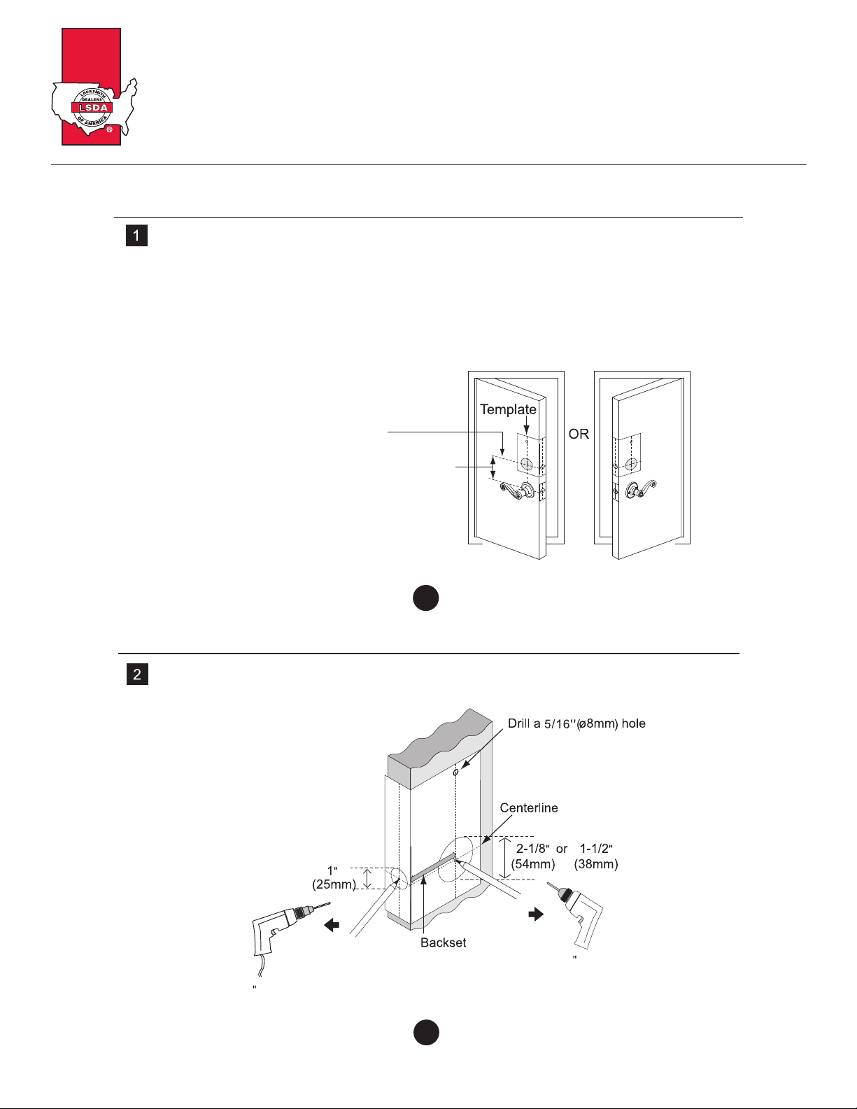
Mark the Door with a Template Sheet (attached separately)
Note: If the door is pre-drilled, please begin with page 13.
a.Use TEMPLATE to mark centerline on door for for deadbolt about 3” to 6”
(75 mm to 150 mm) above the existing knob or lever.
b.Stand so door swings towards you. Align template on centerline and fold template as shown.
Centerline
Mark the door edge approximately 3” to 6”
( 75 mm to 150 mm ) above the entry knob
or lever.
09
INSTALLATION INSTRUCTIONS
DRILL PILOT HOLES
Select a backset. Mark and drill pilot holes as shown below.
Drill a 1/8 pilot hole
Drill a 1/8 pilot hole

Electronic Pushbutton Locks
EL740S
© 2017 IDN, Inc. All rights reserved.
0817
10
INSTALLATION INSTRUCTIONS
DRILL HOLES
a.Drill a 2-1/8” ( 54 mm) or 1-1/2” ( 38 mm ) hole on the door face from both sides
to avoid wood splitting.
11
DRILL HOLES
b.Drill a 1”( 25 mm ) hole on the door edge for the latch.
c. Use the faceplate as a template for mortise and pilot holes. Chisel 1/8”( 3 mm) deep.
Faceplate should fit flush.
d. Install the appropriate latch type as shown below.
INSTALLATION INSTRUCTIONS
Note: For a drive-in latch, please refer to page 14.
d
Electronic Pushbutton Locks
EL740S
© 2017 IDN, Inc. All rights reserved.
0817
12
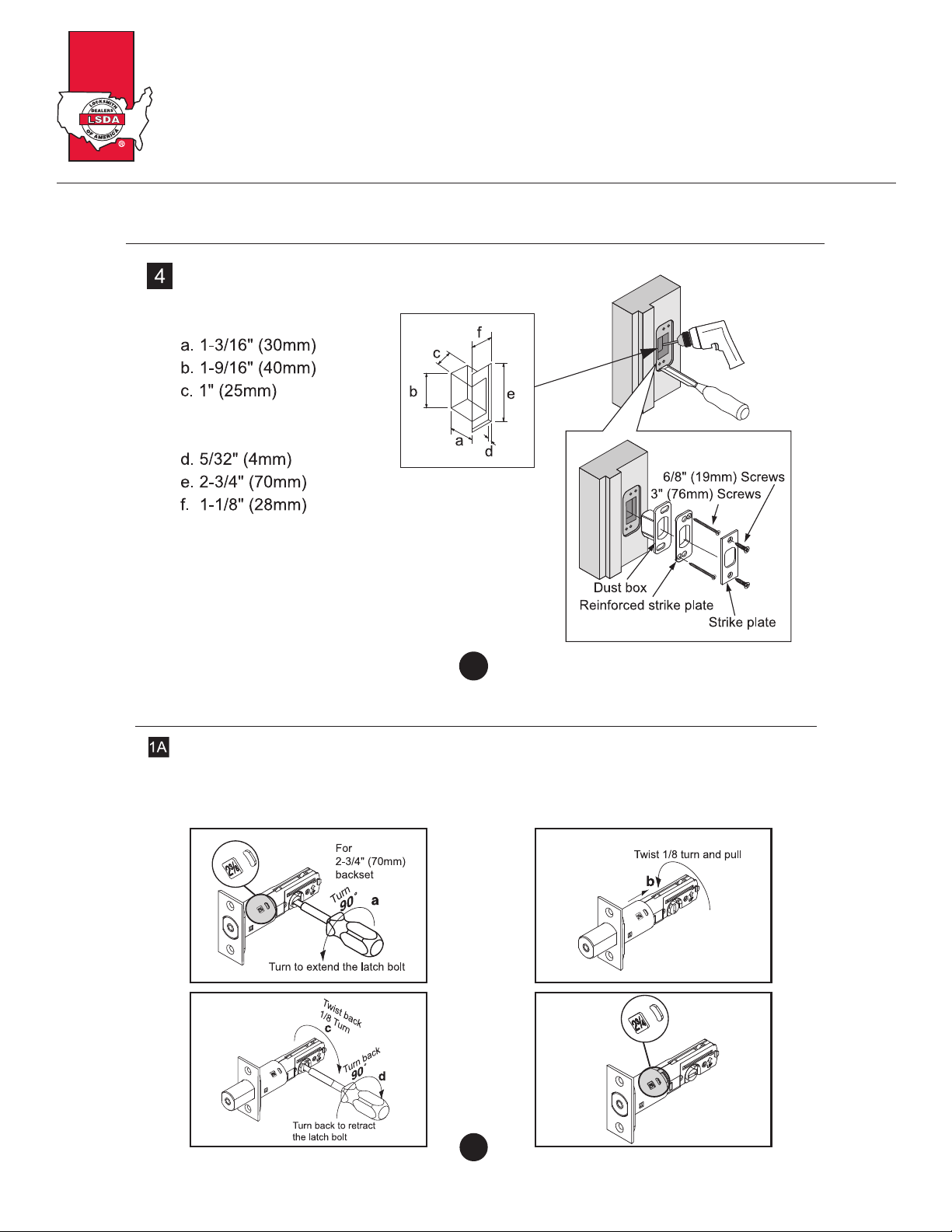
INSTALLATION INSTRUCTIONS
PREPARE DOOR JAMB AND INSTALL STRIKE PLATE
Door jamb hole dimension
Strike dimension
Note: The dust box and reinforced strike plate are optional.
It is recommended to install both of them for maximum
security.
13
LATCH BACKSET ADJUSTMENT
Latch backset adjustment only needs to be made if your door
needs a 2-3/4” ( 70 mm ) backset. Please follow diagrams below as referece.
( Skip this if your door has a 2-3/8” ( 60 mm ) backset )
INSTALLATION INSTRUCTIONS
1.
3. 4.
2.

Electronic Pushbutton Locks
EL740S
© 2017 IDN, Inc. All rights reserved.
0817
1.
3. 4.
2.
14
INSTALLATION INSTRUCTIONS
DRIVE-IN COLLAR or FACEPLATE ADJUSTMENT
In addition to 2-3/8”( 60 mm ) or 2-3/4”( 70 mm ) adjustable backset,
you may change the faceplate to drive-in collar.
(If your door is not a drive-in latch type, please skip this step.)
15
INSTALLATION INSTRUCTIONS
INSTALL LATCH IN MORTISED AREA OR INSTALL DRIVE-IN LATCH
If the door is designed for a standard type latch, please install the latch with 13/16” (20mm)
screws provided.
If a drive-in latch is used, please tap it into the appropriate position.
13/16” (20 mm) screws
Faceplate
Backset
Drive-in Latch
Tap Latch Flush
Wood Block (not included)
(See 1B before installation of drive-in latch)

Electronic Pushbutton Locks
EL740S
© 2017 IDN, Inc. All rights reserved.
0817
Thread the cable through the hole and under the latch.
Thread the tailpiece through the latch in horizontal position.
5
16
Drill a 5/16”(ø8mm) hole on the door when the screw post is installed.
INSTALLATION INSTRUCTIONS
6
17
The bulged part of mounting plate must face toward the door.
Slide cable through the notch of mounting plate.
INSTALLATION INSTRUCTIONS
Table of contents
Other LSDA Lock manuals


