LSK FuelGaugePro FGP-SENSOR User manual

FuelGaugePro
Float-free Fuel Level Sensor
FGP-SENSOR | INSTALLATION MANUAL

1
Table of Contents
Basic information 2
Fuel system requirements 2
Technical specification 3
Installation 4
Installing the fuel sensor 4
Placement on fuel system without fuel pump 5
Placement on fuel system with fuel pump 5
Setting up the FuelGaugePro - Low Fuel Warning Light function 7
Setting up the 3rd party microcontroller-based systems to read
the signal from the sensor 8
Warranty 9
Safety notice 9
Troubleshooting 9
Recycling 10
For more
information

2
Thank you for choosing our products. We strongly advise you to read this user manual
thoroughly. It contains important instructions about installation, setup and use of the
gauge. By obeying these instructions, the product will reward you with long-time
reliability.
Basic information
The FuelGaugePro - Float-free Fuel Level Sensor uses hydrostatic pressure measuring method for
measuring the fuel level without any float or movable parts in the fuel tank and generates
corresponding signal.
The FuelGaugePro - Float-free Fuel Level Sensor can be used together with:
-compatible types of FuelGaugePro displays
-aftermarket fuel gauges trough FuelGaugePro - Sending Unit that simulates resistance float
-FuelGaugePro –Low Fuel Level Warning Light
-microcontroller based system capable to read 12V PWM signal (Arduino etc...)
The Sensor is designed for connection to fuel line via supplied T-plug. After installing, the whole system
needs to be calibrated (except bike specific kits where the system is factory calibrated).
Fuel system requirements
Because of its natural principle, it is not possible to connect it to a hose, into which the fuel is
pumped by a fuel pump or where is a fast fuel flow (fuel systems with return line).
Sensor works only on these types of fuel systems:
-without fuel pump
-with fuel pump
opump must be outside the fuel tank
ono air intake valve on the air input of the tank (there must be an atmospheric pressure
in the fuel tank - not a vacuum)
ono fuel return line causing fast fuel flow

3
Technical specification
Supply voltage: 7 –15V DC
Energy consumption: 2W max without connected gauge
Fuse: electronic non-destructible fuse (0,35A)
Maximal fuel level: 2m
Working temperature: -30°C to + 85°C
Dimensions in milimeters:
Sensor is shockproof and 100% waterproof.
Sensor doesn’t lose its memory after being disconnected from power.
Sensor contains integrated atmospheric pressure changes compensation.

4
Installation
1.Install the Sensor on a suitable place
a) Find the best place for attaching the Sensor.
-Sensor must be physically lower than the fuel tank. It is better to fill the hose up with fuel.
In some cases this can make the measuring more accurate.
-Do not attach the device to the engine or other very hot places. It can handle
temperature up to 80°C.
-Sensor can be installed in any position.
-Check, if all needed wires are long enough to reach desired place.
b) Attach the Sensor on the desired place. You can use a nylon cable ties for example.
c) Drain fuel from the tank or close the petcock.
d) Cut the fuel line that goes from the tank to the engine/fuel pump and insert the T-plug.
e) Connect the Sensor to the T-plug using a piece of fuel tube.

5
Detailed placement on fuel systems without fuel pump:
Detailed placement on fuel systems with fuel pump:

6
2. Connect the wires
Red supply wire:
Connect after the ignition
switch, so that the gauge
switches itself on with the
ignition key.
Black supply wire:
Use the wire shoe and screw it
on some place of the frame, or
even to the (-) pole of the
battery. It can be also attached
to any other (-) wire (usually
black) using the cut in
connector included in the
package.
Supply wires are protected
against reversed polarity.
Display panel connector:
Connect the FuelGaugePro
original display panel or Low Fuel Warning Light here.
Never connect any wires of display panel connector together. It can destroy the whole Sensor!

7
If you are owner of FuelGaugePro - Low Fuel Warning Light, follow next steps.
Setting up the FuelGaugePro - Low Fuel Warning Light function
Use only if you are connecting the Sensor together with FuelGaugePro - Low Fuel Warning Light kit.
It is needed to switch the output from continuous signal (factory settings) used for gauges to on/off
signal needed for Warning Light.
a) Connect the Warning Light to the Display panel connector.
b) Power the Sensor up.
c) Hold the magnet included in package
with Warning Light near one of two
possible places of the Sensor as you see
on the picture. If Sensor recognizes the
magnet, the Warning Light start flashes
slowly.
d) Hold the magnet for ca. 40-60 second
until the connected Warning Light start
flashing very fast (strobe).
(There are total 3 different flashing
speeds from slow to fast. You need to
wait for the fastest one.)
e) Take the magnet out.
Set the threshold when the Warning Light is switched on/off.
a) Fill the required fuel amount to the tank and make sure you have petcock opened well to all its
hydrostatic pressure can push on the Sensor.
b) Proximity the included magnet as shows the picture. You should see the Warning Light start
flashes slowly.
c) Hold the magnet on place few second until the Warning Light start flashes way faster. After that
immediately remove the magnet. Your threshold is now set up.
Obrázek vyměnit.
Reaguje to na opačném
konci senzoru!!

8
If you want to use the sensor without any FuelGaugePro display panel and
using it in your own gauge design, follow next steps.
Setting up the 3rd party microcontroller-based systems to read the
signal from the FuelGaugePro –Float-free Fuel Level Sensor
Use only if you will use the Sensor together with another device capable to read Sensor signal –DIY
dashboard projects etc...
Sensor output circuit: See the picture.
Output signal: 0-12V PWM
Frequency: 100Hz
Duty cycle represents the hydrostatic pressure.
The atmospheric pressure changes are compensated.

9
Warranty
Product is covered by 2 years Limited Warranty (from the date of purchase). Limited Warranty covers
any defects in material or manufacturing defects under normal use and maintenance. We reserve the
right not to accept the claim in the case of mechanical damage that could be related to the defect of
the product or if the product was disassembled by unauthorized service.
This limited warranty also does not cover any problem that is caused by conditions, malfunctions or
damage not resulting from defects in material or workmanship.
During warranty period, we will repair or replace defective product or defective parts. To obtain
warranty service, you must first contact us to determine the problem and the most appropriate solution
for you.
Safety notice
This device should be installed by specialized garage or service. Inappropriate mounting or electrical
connection may result in damaging this or any other electrical devices in the motorcycle. Improper
installation of fuel hoses can cause the fuel to leak and a fire resulting in damage the motorcycle and the
owner’s health.
Device is not approved for use at public roads. You use it at your own risk and responsibility.
Troubleshooting
If you obey all the instructions, this fuel gauge should work properly without problems. In case of any
problems, feel free to contact us.
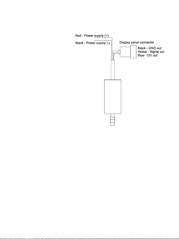
-If the gauge doesn’t show anything on the display, check out all the connections of the device.
-If the gauge shows nonsense and is calibrated correctly, try checking, if you filled up the fuel hoses
like explained on page three.
-Wrong data display is often caused by dirty fuel strainer in the fuel tank, dirty fuel filter if the
gauge is connected after it or just marginally opened fuel cock. In case of problems, try to
check/replace these parts. This fault is often represented by the amount of fuel dependant on
engine revs. Pressure sensor fail is very improbable –problems are usually caused by something
else.
If nothing helps, contact us.

10
Recycling
Retired device should be given to places specified for retrieving electrical garbage. Package should be
thrown into a specific container for recycled garbage.
Device meets RoHS Directive.
www.lskelectronics.com
Product website:
Table of contents
Other LSK Motorcycle Accessories manuals