LSLIDAR C32 User manual

C32
USER MANUAL
V4.0.9
2022.12
LeiShen Intelligent System Co., LTD
http://www.lslidar.com/

Safety Instruction
Before using the product, please read and follow the instructions of this manual
carefully, and refer to relevant national and international safety regulations.
∆Attention
Please do not disassemble or modify the lidar privately. If you need special
instructions, please consult our technical support staff.
∆Laser Safety Level
The laser safety of this product meets the following standards:
● IEC 60825-1:2014
● 21 CFR 1040.10 and 1040.11 standards, except for the deviations (IEC 60825-
1, third edition) stated in the Laser Notice No. 56 issued on May 8, 2019. Please
do not look directly at the transmitting laser through magnifying devices (such
as microscope, head-mounted magnifying glass, or other forms of magnifying
glasses).
Eye Safety
The product design complies with Class 1 human eye safety standards. However,
to maximize self-protection, please avoid looking directly at running products.
∆Safety Warning
In any case, if the product is suspected to have malfunctioned or been damaged,
please stop using it immediately to avoid injury or further product damage.
Housing
The product contains high-speed rotating parts, please do not operate unless
the housing is fastened. Do not use a product with damaged housing in case of
irreparable losses. To avoid product performance degradation, please do not
touch the photomask with your hands.
Operation
This product is composed of metal and plastic, which contains precise circuit
electronic components and optical devices. Improper operations such as high
temperature, drop, puncture or squeeze may cause irreversible damage to the
product.
Power Supply
Please use the connecting cable and matching connectors provided with the
lidar to supply power. Using cables or adapters that are damaged or do not meet

the power supply requirements, or supply power in a humid environment may
cause abnormal operation, fire, personal injury, product damage, or other
property loss.
Light Interference
Some precise optical equipment may be interfered with by the laser emitted by
this product, please pay attention when using it.
Vibration
Please avoid product damage caused by strong vibration. If the product's
mechanical shock and vibration performance parameters are needed, please
contact us for technical support.
Radio Frequency Interference
The design, manufacture and test of this product comply with relevant
regulations on radiofrequency energy radiation, but the radiation from this
product may still cause other electronic equipment to malfunction.
Deflagration and Other Air Conditions
Do not use the product in any area with potentially explosive air, such as areas
where the air contains high concentrations of flammable chemicals, vapours or
particles (like fine grains, dust or metal powder). Do not expose the product to
the environment of high-concentration industrial chemicals, including near
evaporating liquefied gas (like helium), so as not to impair or damage the product
function.
Maintenance
Please do not disassemble the lidar without permission. Disassembly of the
product may cause its waterproof performance to fail or personal injury.

Table of Contents
1. PRODUCT PROFILE .................................................................................................. 1
1.1 OVERVIEW ................................................................................................................ 1
1.2 MECHANISM ............................................................................................................. 1
1.3 SPECIFICATIONS ........................................................................................................ 1
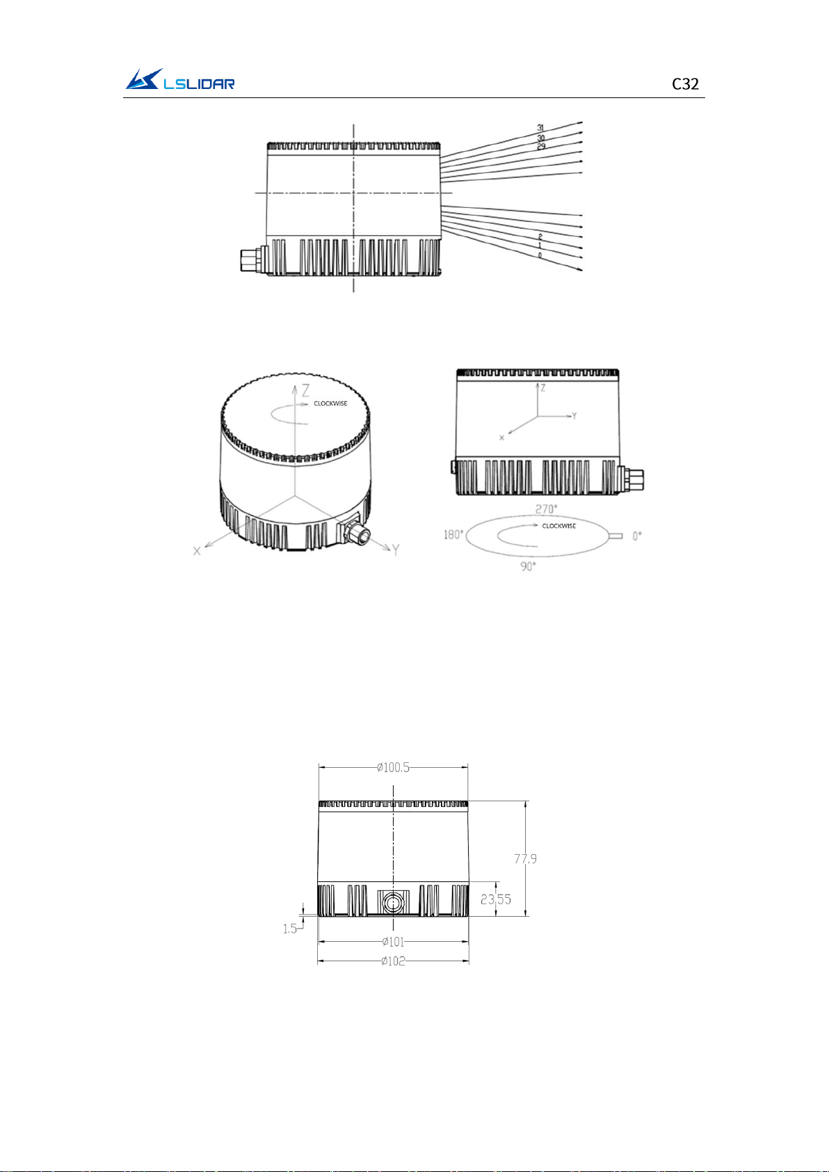
1.4 MECHANICAL STRUCTURE........................................................................................ 2
1.5 LIGHT SPOT............................................................................................................... 4
2. ELECTRICAL INTERFACE......................................................................................... 5
2.1 POWER SUPPLY......................................................................................................... 5
2.2 CONNECTORS ........................................................................................................... 6
3. GET READY ...............................................................................................................10
3.1 LIDAR CONNECTION............................................................................................... 10
3.2 SOFTWARE PREPARATION ...................................................................................... 10
4. USAGE GUIDE .......................................................................................................... 11
4.1 OPERATION UNDER WINDOWS OS ......................................................................12
4.1.1 Lidar Configuration...................................................................................... 12
4.1.2 Windows Client Interface .......................................................................... 13
4.1.3 Operation Procedure ..................................................................................15
4.1.4 Point Cloud Data Parsing ...........................................................................15
4.1.5 Parameter Config Example of Lidar Network Communication Mode
...................................................................................................................................16
4.1.6 Note................................................................................................................18
4.2 ROS DRIVER OPERATION UNDER LINUX OS ........................................................21
4.2.1 Hardware Connection and Test ................................................................21
4.2.2 Software Operation Example ....................................................................22
5. COMMUNICATION PROTOCOL .........................................................................23
5.1 MSOP PROTOCOL ................................................................................................. 24
5.1.1 Format............................................................................................................24
5.1.2 Data Package Parameter Description...................................................... 25
5.2 DIFOP PROTOCOL.................................................................................................27

5.3 UCWP PROTOCOL ................................................................................................29
5.3.1 Configuration Parameters and Status Description ...............................30
5.3.2 Configuration Package Example...............................................................31
6. TIME SYNCHRONIZATION................................................................................... 32
6.1 GPS SYNCHRONIZATION........................................................................................ 32
6.2 EXTERNAL SYNCHRONIZATION............................................................................... 34
6.3 GPTP SYNCHRONIZATION......................................................................................34
6.4 LIDAR INTERNAL TIMING ........................................................................................35
7. ANGLE AND COORDINATE CALCULATION .................................................... 35
7.1 VERTICAL ANGLE ....................................................................................................35
7.2 HORIZONTAL ANGLE ..............................................................................................36
7.2.1 Horizontal Angle Calculation of Single Echo Mode ..............................36
7.2.2 Horizontal Angle Calculation of Dual Echo Mode................................. 37
7.3 CARTESIAN COORDINATE REPRESENTATION..........................................................39
7.4 JUDGMENT OF ONE FRAME OF DATA ....................................................................40
8. ACCURATE TIME CALCULATION........................................................................ 40
8.1 CALCULATION OF DATA PACKET END TIME...........................................................40
8.2 ACCURATE TIME CALCULATION OF CHANNEL DATA .............................................41
8.3 END TIME OF DATA POINT.....................................................................................41
APPENDIX A. MAINTENANCE ................................................................................. 42
APPENDIX B. POWER SUPPLY REQUIREMENTS ...............................................42

1
1. Product Profile
1.1 Overview
The C32 lidar realizes 360° three-dimensional high-speed scanning with 32
dense laser beams. It reaches a detection distance of up to 150 m, measurement
accuracy of ±3 cm, and a minimum vertical angular resolution of 1°. This lidar
sensor is widely used in unmanned driving, automotive ADAS, intelligent
transportation, service robot, logistics, surveying and mapping, security, industry,
ports and other fields.
1.2 Mechanism
The C32 mechanical lidar adopts the Time of Flight method. The lidar starts
timing (t1) when the laser pulses are sent out. And when the laser encounters
the target object and the light returns to the sensor unit, the receiving end stops
timing (t2).
Distance = Speed of Light*(t2 – t1)/2
Figure 1.1 Time of Flight
1.3 Specifications
Table 1.1 Specifications of C32
Model
C32
Detection Method
ToF
Wavelength
905 nm
Laser Class
Class 1 (eye-safe)
Channels
32

2
Detection Range
100 m @10% reflectivity; 150 m @70% reflectivity
Range Accuracy
±3 cm
Data Point Generating Rate
(Single Echo Mode)
640,000 pts/sec
Data Point Generating Rate
(Dual Echo Mode)
1,280,000 pts/sec
FOV
Vertical
-16°~+15°
Horizontal
360°
Angular
Resolution
Vertical
1° (Uniform Distribution)
Horizontal
5 Hz: 0.09º / 10 Hz: 0.18º / 20 Hz: 0.36º
Scanning Rate
5 Hz / 10 Hz / 20 Hz
Communication Interface
Ethernet / PPS
Operating Voltage
+12 V~+32 VDC
Operating Power
12 W (Typical*); 25 W (Max)
Divergence Angle
Fast Axis: 5.7 mrad; Slow Axis: 8.7 mrad
Operating Temperature
-20℃~+60℃**
Storage Temperature
-40℃~+85℃
Shock Test
500 m/sec², lasting for 11 ms
Vibration Test
5 Hz~2000 Hz, 3G rms
IP Grade
IP67
Dimensions
Ф102 mm*77.9 mm
Weight
1040 g (Standard Edition)
*Typical operating power refers to work at room temperature; the maximum
operating power in special scenarios (such as low temperature startup) is lower
than 25 W.
**When the lidar is used outdoors, a sunshade cover or other dissipation device
is required. For example:
1.4 Mechanical Structure
The C32 lidar is equipped with 32 pairs of laser transmitter and receiver modules.
Its motor is driven at a rotation speed of 5 Hz/10 Hz/20 Hz to cover a 360° scan
range.

3
Figure 1.2 Laser Beam Distribution
Figure 1.3 Coordinates & Scanning Direction
Note: As shown above, the cable connector of the lidar marks its zero-angle
position. (It can be changed to the opposite of the cable connector in the
Windows Client software.) When the laser beams pass through the position of
the cable connector, the azimuth angle of the corresponding data block in the
output UDP packet is 0°.
Figure 1.4 C32 Dimensions

4
Figure 1.5 C32 Lidar Base
Note: Excessive temperatures have an impact on the life of the lidar. Please
ensure that the lidar is at the correct operating temperature. If the operating
temperature exceeds 38°C or if the lidar is exposed to the sun for a long period
of time, it is important to use it with a heat sink. You can contact us for cooling
solutions.
Figure 1.6 C32 Mechanical Drawing (unit: mm)
1.5 Light Spot
The light spot of C32 lidar is a vertical oval. Its vertical divergence angle is 8.7
mrad, and the horizontal divergence angle is 5.7 mrad. The spot size at any
distance can be calculated by multiplying the divergence angle by the distance.
For example, the calculation of a spot at 10 m is as follows:
Vertical direction at 10 m: 10*8.7*10-3=87 mm
Horizontal direction at 10 m: 10*5.7*10-3=57 mm

5
Figure 1.7 Light Spot Demonstration
2. Electrical Interface
2.1 Power Supply
This lidar’s power input range is 9 V~36 VDC. If other DC power supply is
adopted, the recommended output voltage is 12 V, 19 V, 24 V or 32 VDC. The
output power should be ≥25 W (the lidar requires a large instantaneous current
to start, and a small starting current may cause its failure to start normally). The
output ripple noise should be <100 mV (Vp-p) and output voltage accuracy <5%.
The higher the power supply voltage and the stronger the discharge capacity,
the more severe the impact on the lidar. Before mounting the lidar, please
contact our technical support personnel for power supply environment
evaluation to avoid damage.
The length of the lidar power supply cable is 5~10 m, and the power supply
voltage needs to be over 19 V. If the power cable is more than 10 m long, then
it is recommended to use a 220 VAC adapter to supply power (DC long-distance
power supply is not recommended). This information is based on experience and
is for reference only. For specific power supply environment requirements,
please refer to Appendix B: Power Supply Requirements for details.
Table 2.1 Electrical Parameter
Item
Min.
Recommended
Max.
Note
Supply
Voltage
9 V
12 V/19 V
/24 V/32 V
36 V
If the power supply voltage is not
within this range, it may cause
inaccurate ranging or irreversible
damage. It is not allowed to use a
power supply lower than 9 V or higher
than 32 V for long-term power supply.
The output power of the power supply
should be at least 25 W.

6
Ripple
-
-
100 mV
The smaller the ripple, the better. Too
much ripple will cause irreversible
damage to the hardware.
Working
Current
-
900 mA
1500
mA
12 V power supply at 10 Hz
recommended. When scanning at 20
Hz, the lidar power consumption will
also be higher than the recommended
value.
GPS PPS
-13 V
13 V
The period is 1 second, the
recommended pulse width is more
than 1 ms.
GPS REC
-13 V
13 V
RS232 level, baud rate 9600 bps,
compatible with TTL and RS232 level.
2.2 Connectors
Male connector on the lidar base
There is an 8-pin male connector on the side of the C32 lidar base, and the wires
can be led out by using an extension cable with a female socket, an adapter cable
or an interface box. The cable connector model on the side of the C32 lidar base
is L102-M12-Z08A118. You can use an extension cable with a female connector
or an adapter cable to lead out the wires to achieve system power supply and
data communication. The lidar supports GPS timing function, and the cable
connector is shown in Figure 2.1 below.
Figure 2.1 Cable Connector on the Lidar Base
The definition of the 8-pin male connector is shown in the table below.
Table 2.2 Pin Definition of the 8-pin male connector
Pin
Definition
Level
Description
1
VIN
9~36 V
Power+
2
TD_P
-1~1 V
Ethernet data flow: lidar external devices
3
TD_N
-1~1 V
Ethernet data flow: lidar external devices
4
RD_P
-1~1 V
Ethernet data flow: external devices lidar
5
RD_N
-1~1 V
Ethernet data flow: external devices lidar
6
GPS_PPS
-13~13 V
GPS Sync Pulse/External Sync Pulse
7
GPS_Rec
-13~13 V
GPS latitude & longitude, hour/minute/second
8
GND
0V
Power-

7
There are three kinds of cables for you to choose to connect the lidar, see the
details below.
(1) Adapter Cable (Default)
In order to facilitate wiring, LeiShen Intelligent provides an adapter cable. The
cable and its wiring definition are as follows:
Figure 2.2 Adapter Cable
Figure 2.3 Wiring Definition of the Adapter Cable
Table 2.3 Connectors Description of the Adapter Cable
S/N
Connector
Note
P1
Lidar Connecting Port
Aviation terminal, whose wiring definition is
the same as the extension cable, model: L102-
M12-T08A02M
P2
Power Port
Connect external power supply, connector
specification: DC5.5*2.1
P3
Standard Ethernet Port
Fast Ethernet, standard RJ45 connector with
standard 568B wiring scheme
P4
Timing Synchronization Port
DB-9 connector, REC baud rate: 9600 bps;
the recommended PPS pulse width is to
exceed 1 ms, period: 1s; PPS and REC signals
are compatible with both TTL and RS232
levels
Note: Pin 2 of P2 and pin 5 of P4 connect to the same ground wire.

8
Table 2.4 Wire Definition of P1
S/N
Wire Color & Size
Definition
Description
1
Red (20AWG)
VCC
Power+
2
Orange (24AWG)
Ethernet TX1+
-
3
Light Orange (24AWG)
Ethernet TX1-
-
4
Light Blue (24AWG)
Ethernet RX2+
-
5
Blue (24AWG)
Ethernet RX2-
-
6
Yellow (20AWG)
GPS_PPS
GPS Sync Pulse/External Sync
Pulse
7
White (20AWG)
GPS_Rec
GPS latitude & longitude,
hour/minute/second
8
Black (20AWG)
GND
Power-
(2) Extension Cable (Optional)
If an extension cable is needed, LeiShen Intelligent can provide an optional
customized extension cable. When plugging and unplugging the cable, be careful
not to plug it with power on, otherwise it will cause irreversible damage. To plug
the cable, align with the key position and insert it into the connector, and then
rotate the cover to fix it to ensure good contact and not loose. To unplug it, first
rotate the cover, loosen it and then pull it out. Do not use brute force to avoid
terminal deformation or even short circuit. If the connector is damaged, please
contact technical support in time to replace it. The connector terminal model of
the extension cable is: L102-M12-T08A02M.
Figure 2.4 C32 Lidar Extension Cable (unit: mm)
Table 2.5 Wire Definition of the Lidar Extension Cable
S/N
Wire Color & Size
Definition
Description
1
Red (20AWG)
VCC
Power+
2
Light Blue (24AWG)
TD_N
Ethernet TX-
3
Blue (24AWG)
TD_P
Ethernet TX+
4
Light Orange (24AWG)
RD_N
Ethernet RX-
5
Orange (24AWG)
RD_P
Ethernet RX+
6
Yellow (20AWG)
GPS_PPS
GPS Sync Pulse/External Sync
Pulse
7
White (20AWG)
GPS_Rec
GPS latitude & longitude,
hour/minute/second
8
Black (20AWG)
GND
Power-
(3) Interface Box (Optional)
To facilitate the testing and connection of connectors, the C32 lidar can also be

9
equipped with an interface box, which is not a necessary accessory for lidar
operation. On the interface box, there is a Φ5.5*2.1 mm DC socket, an indicator
light, an RJ45 network port and a 6-pin GPS port, as shown in the figure below.
Figure 2.5 Interface Box
The GPS interface socket specification of the interface box is SM06B-SRSS-TB
of JST, and the recommended plug interface for the external GPS module is SHR-
06V-S-B of JST. The interface definitions are as follows:
Table 2.6 GPS Interface Definition
PIN
Function Definition
I/O
Requirement
1
PPS Sync Signal
I
TTL level ranges from 3.3 V to 12 V, its
period is 1 second, and the recommended
pulse width is over 1 ms
2
GPS Power Supply 5 V
O
No hot plug or unplug
3
GPS_GND
O
Good contact
4
GPS (latitude/longitude,
hour/ minute/second)
I
REC baud rate is 9600 bps, compatible with
TTL and RS232 levels
5
GPS_GND
O
Good contact
6
NC
-
-
If you need multiple lidars to build maps at the same time, LeiShen Intelligent
provides a GPS synchronization board to solve the problem of insufficient timing
signal driving capability of your controller. This item is optional, please contact
our technical support for information.
Note: The temperature resistance of the wire is -40°C~105°C, and cold-resistant
materials are used.

10
3. Get Ready
3.1 Lidar Connection
To get ready for the lidar operation, please connect the lidar to the computer as
shown in figure 3.1.
Figure 3.1 Connecting Lidar and Computer
Note: Under any circumstances, it is forbidden to plug and unplug the aviation
terminal with power on. When plugging and unplugging the GPS module from
the GPS port of the interface box, or connecting or disconnecting the signal from
the GPS pin of the cable, please make sure that the lidar is powered off.
3.2 Software Preparation
This lidar can be operated under both Windows operating system and Linux
operating system. Software needed is as follows:
Wireshark: to capture the ARP (Address Resolution Protocol) packets.
Note: Wireshark is a third-party software, and you may need to download it by
yourself. LeiShen Intelligent bears no responsibility for any copyright and
commercial disputes caused by users’ use of the software.
To view the point cloud data generated by the lidar, you can either use the
Windows Client or the ROS Drive Program.
Windows Client (optional): a host computer software to view point cloud images
under Windows operating system, which is also referred to as “point cloud
display software”. Simple functions like parameter configuration, lidar test and

11
fault detection can be realized through the client, too.
⚫Software Acquisition
This Windows Client has been pre-stored in the USB flash drive provided along
with the lidar. It can also be obtained from the sales or technical support
personnel. No installation is required to the Client.
⚫Operating Environment
This software can only run under the Windows x64 operating system at present.
The computer configuration requirements for installing the software are: CPU:
Intel(R) Core (TM) i5 or higher; Graphics Card: NVIDIA GeForce GTX750 or
higher achieves the best effect, otherwise the display of the point cloud may be
affected. And the computer graphics card must support OpenGL 2 or higher
graphics acceleration to display the point cloud normally.
⚫Supplemental Software
To use the Windows Client, it is necessary to install the WinPcap third-party
library. This software has also been pre-stored in the USB flash drive provided
with the lidar.
To install the WinPcap software, please follow the following steps:
Step 1. Insert the USB driver into the computer port and open it.
Step 2. Find the WinPcap installation file and double-click it to initiate the
installation.
Step 3. Click “next” to enter the installation path selection interface.
Step 4. Click “next” to enter the installation interface.
Step 5. Click the “install” button, and wait for the installation to be completed.
ROS Driver Program (optional): to view the point cloud data under Linux
operating system. This program has been pre-stored in the USB flash drive
provided with the lidar. It can also be obtained from the sales or technical
support personnel. No installation is required.
4. Usage Guide
This part states the operation instructions of the LSC32 Windows Client and
ROS driver presented by the LeiShen Intelligent System Co. Ltd.

12
4.1 Operation Under Windows OS
4.1.1 Lidar Configuration
The default IP address and port number of the lidar network are as follows:
Table 4.1 Default Lidar Network Configuration
IP Address
UDP Device Package Port
Number
UDP Data Package Port
Number
Lidar
192.168.1.200
2368 (Fixed)
2369 (Fixed)
Computer
192.168.1.102
2369
2368
Note: The lidar IP (local IP) and the computer IP (destination IP) cannot be set to
the same, otherwise the lidar will not work normally.
In the multicast mode, no two destination ports should be set to the same port
number.
The lidar IP range are forbidden to be set to
1) Class D IP address (multicast address: i.e. 224.0.0.0~ 239.255.255.255)
2) Class E IP address (reserved address: i.e. 240.0.0.0~ 255.255.255.254)
3) Broadcast addresses (i.e. 255.255.255.255 and xx.x.255 for each network
segment)
4) Special class IP addresses (0.x.xx and 127.xxx)
The lidar destination IP are forbidden to be set to
1) Class E IP address address (i.e. 240.0.0.0 to 255.255.255.254)
2) Special class addresses (0.x.xx and 127.x.x.x)
When connecting to the lidar, if the computer IP and the lidar IP are in different
network segments, the gateway is needed to be set; if they are in the same
network segment, only different IPs are needed to be set, for example:
192.168.1.x, and the subnet mask is 255.255.255.0. If you need to find the
Ethernet configuration information of the lidar, please connect the lidar to the
computer and use “Wireshark” to capture the ARP packet of the device for
analysis. For the feature identification of the ARP packet, see the figure below.

13
Figure 4.1 Wireshark Captures ARP Packet
4.1.2 Windows Client Interface
The software interface includes menu area, tool bar area, 3D window area, data
table area, etc.
Figure 4.2 Windows Client Interface
Note: To view the software version, click “Help->About” in the toolbar.
The point cloud display interface supports the following operations:
1) Zoom in/out the display interface with the mouse wheel; hold the right mouse
button and drag it up/down to zoom in/out.
2) Hold the left mouse button and drag it to adjust the angle of view;

14
3) Hold the mouse wheel and drag it to pan the display interface; or hold the
shift key on the keyboard and the left mouse button to pan the interface.
Menu button function introduction
⚫Lidar Menu
Button
Description
Connect/disconnect lidar
Clear screen
Show/hide coordinate
Three-view option: set the observation angle from
top, front, and left.
Pause point cloud image and data generating
Show/hide measurement grids
Note: Click to show measurement grids if needed. There are altogether
20 circles and 40*40 grids, the radius of each two adjacent circles differs by 10
m. The difference between every two grids (horizontal or longitudinal) is 10 m.
And the radius of the outermost circle is 200 m.
The grids and circles make it easy to view the position of the point cloud. The
direction of the coordinate axis in the 3D display interface is consistent with the
direction of the X-Y axis in the point cloud reference system.
⚫Offline Menu
Button
Description
Open offline data
Record and save data, valid only when lidar receives data in real time
Skip to the beginning
When paused, view the previous frame;
When playing, rewind (click multiple times to
select 2x, 3x, 1/2x, 1/4x and 1x speed)
Click to start playing after the point cloud file is loaded
When playing, click to pause
When paused, view the next frame;
When playing, fast forward (click multiple times
to select 2x, 3x, 1/2x, 1/4x and 1x speed)
Skip to the end

15
Drag the progress bar or enter the frame number to skip to the specified
position
⚫Setup Menu
Button
Description
Open lidar parameter
form
The upper part of the form shows the lidar
configuration. The parameters include local IP,
destination IP, subnet mask, gateway, local port,
destination port, and motor speed setting
(5Hz/10Hz/20Hz can be selected under combo
box), whether to obtain the local time, Mac address
information, and device packet sending interval.
The lower part shows the real-time status
information. According to the DIFOP status packet
sent out regularly by the lidar, the current status
information is displayed, including GPS position
information, satellite time information, motor speed,
current lidar IP, and current lidar port number.
Select laser channel
Vertical Angle column represents the vertical angle
of the corresponding channel data and Channel
column represents the data sequence number
corresponding to the channel.
Save the data in .csv
format
Set the mode of echo
Dual echo, strongest echo, second echo
Set the display mode
of the point cloud
Intensity, laser ID, azimuth angle, etc.
4.1.3 Operation Procedure
Step 1. Set the data port number (default 2368), device package port (telemetry
port in the following picture) number (default 2369), and multicast IP.
Step 2. Click to receive the lidar data in real time.
Step 3. The data table contains (PointID, Points_m_XYZ, adjustedtime, Azimuth,
Distance, Intensity, Laser_id, timestamp).
4.1.4 Point Cloud Data Parsing
Table of contents
Other LSLIDAR Accessories manuals