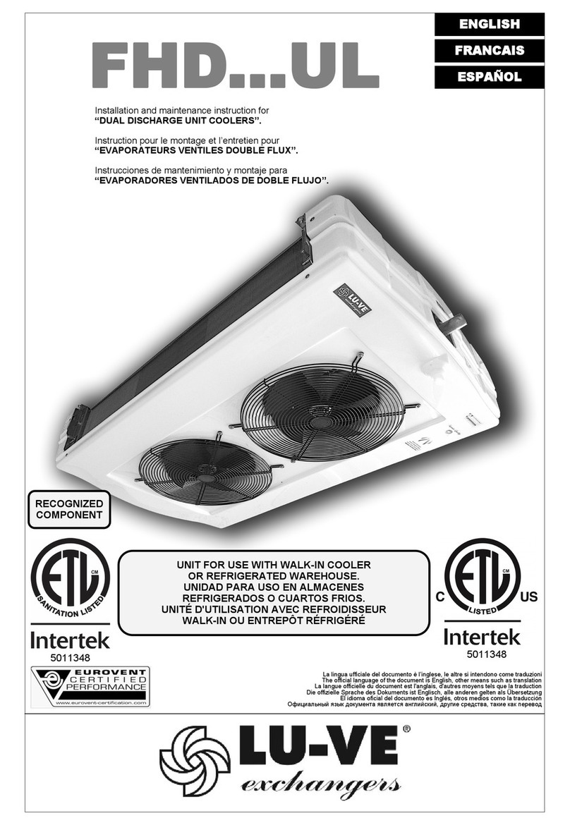
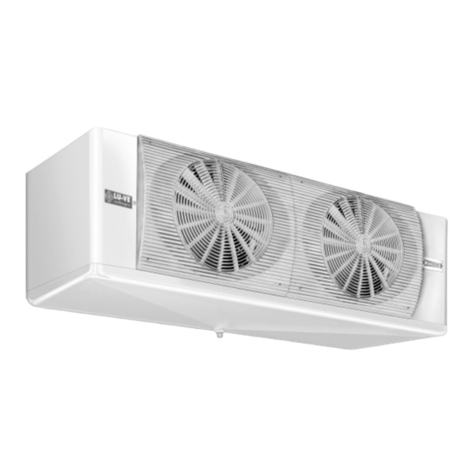
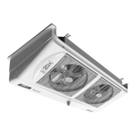
LU-VE BHDN Technical specifications

BHDN - BHDS BENEFIT
SHDN - SHDS SUPER
BMDN - BMDS BENEFIT
SMDN - SMDS SUPER
Istruzione per il montaggio e la manutenzione per
“AEROEVAPORATORI A DOPPIO FLUSSO”.
Installation and maintenance instruction for
“DUAL DISCHARGE UNIT COOLERS”.
Instruction pour le montage et l’entretien pour
“EVAPORATEURS VENTILES DOUBLE FLUX”.
I TA L I A N O
ENGLISH
FRANCAIS
DEUTSCH
P O L S K I
Montage und wartungsanleitung für
“ZWEISEITIG AUSBLASENDE HOCHLEISTUNGSLUFTKÜHLER”.
Instrukcja instalacji, eksploatacji i konserwacji dla
“CHŁODNIC POWIETRZA Z DWUSTRONNYM WYRZUTEM
POWIETRZA”.
BHDN - BHDN
SHDN - SHDS
“SAFESHELL”
BMDN - BMDS
SHDN - SHDS
“STEEL PROTECTED”
1

I TA L I A N O Dichiarazione del fabbricante. ENGLISH MANUFACTURERS DECLARATION OF INCORPORATION.
Riferimento EC Direttiva Macchine 89/392 CEE e successivi emendamenti.
Gli apparecchi sono stati progettati e costruiti per poter essere incorporati in macchine come definito
dalla Direttiva Macchine 89/392 CEE e successivi emendamenti e sono rispondenti alle seguenti
norme:
• EN 60335-1 (CEI 61-50) Sicurezza degli apparecchi elettrici d’uso domestico e similare. Norme
Generali.
• CEI-EN 60335-2-40 Sicurezza degli apparecchi d’uso domestico e similare - parte 2ª. Norme
particolari per le pompe di calore elettriche, per i condizionatori d’aria e per i deumidificatori.
• Direttiva 89/336 CEE e successivi emendamenti. Compatibilità elettromagnetica.
• Bassa tensione - Riferimento Direttiva 73/23 CEE.
Tuttavia non è ammesso mettere i nostri prodotti in funzione prima che la macchina nella quale essi so-
no incorporati o della quale essi sono una parte sia stata dichiarata conforme alla legislazione in vigore.
PRECAUZIONI: Messa in guardia contro eventuali rischi d’infortunio o di danneggiamento
dei materiali in caso d’inosservanza delle istruzioni.
A) Per le operazioni di movimentazione, installazione e manutenzione, è obbligatorio:
1 - Personale abilitato all’uso dei mezzi di movimentazione (gru, carrello elevatore, etc.).
2 - Uso dei guanti di protezione.
3 - Non sostare sotto il carico sospeso.
B) Prima di procedere ai collegamenti elettrici, è obbligatorio:
1 - Personale abilitato.
2 - Assicurarsi che il circuito elettrico d’alimentazione sia aperto.
3 - L’interruttore del quadro generale d’alimentazione sia lucchettato in posizione di aperto.
C) Prima di procedere ai collegamenti dei collettori/distributori, è obbligatorio:
1 - Personale abilitato.
2 - Assicurarsi che il circuito d’alimentazione sia chiuso (assenza di pressione).
3 - Durante l’operazione di saldatura, assicurarsi di indirizzare la fiamma in modo da non investire la
macchina (eventualmente interporre una protezione).
D) SMALTIMENTO: I prodotti LU-VE sono composti da:
Materiali plastici: polistirolo, ABS, gomma.
Materiali metallici: ferro, acciaio inox, rame, alluminio (eventualmente trattati).
Per i liquidi refrigeranti seguire le istruzioni dell’installatore dell’impianto.
E) Togliere la pellicola trasparente di protezione dalle parti metalliche verniciate.
Reference EC Machine Directive 89/392/EEC and successive modifications.
The products are provided for incorporation in machines as defined in the EC Machine
Directive 89/392/EEC and successive modifications according to the following safety
standard references:
• EN 60335-1 (CEI 61-50) Safety of household and similar electrical appliances. General requirements.
• CEI-EN 60335-2-40 Safety of household and similar electrical appliances - Part 2: Particular require-
ments for electrical heat pumps, air-conditioners and dehumidifiers.
• Machine Directive 89/336 EEC and successive modifications. Electromagnetic compatibility.
• Low tension - Reference Directive 73/23 EEC.
However it is not allowed to operate our equipment in advance before the machine incorporating the products
or making part thereof has been declared conforming to the EC Machine Directive.
PRECAUTIONS: Accidents warning to personal injury or equipment damage due to negligence for complying to
instructions.
A) For moving installing and maintenance operations it is mandatory to comply as follows:
1 - Employ authorized personnel only for using moving equipment (cranes, fork elevators, etc.).
2 - Wearing of work gloves.
3 - Never stop below a suspended load.
B) Before to proceed with elestrical wirings it is mandatory to comply as follows:
1 - Authorized personnel only shall be employed.
2 - Make sure the power line circuit is open.
3 - The main switch on the general power panel is open and pad-locked in this setting.
C) Before to proceed with the collectors/distributors connections it is mandatory to com-
ply as follows:
1 - Authorized personnel only shall be employed.
2 - Make sure the supply circuit is closed (no pressure).
3 - When performing welding operations, make sure the flame nozzle is not aimed toward the equip-
ment (insert a shield if required).
D) DISPOSAL: LU-VE products are made of:
Plastic materials: polyethylene, ABS, rubber.
Ferrous materials: iron, stainless steel, copper, aluminium (possibly processed).
Refrigerants liquids: follow the instructions relevant to the equipment installation.
E) Remove the transparent protection film from varnished metallic parts.
DEUTSCH HERSTELLER-ERKLÄRUNG
Hersteller-Erklärung im Sinne der EG-Richtlinie Maschinen 89/392/EWG und nachfolgende
Ergänzungen.
Die Produkte sind in Überreistimmung mit der EG Richtlinie 89/392/EWG und nachtfolgende Ergänzungen
entwickelt, konstruiert und gefertigt und entsprechen folgenden Normen:
• EN 60335-1 (CEI 61-50) Sicherheit elektrischer Geräte für den Hausgebrauch und
ähnliche Zwecke Teil 1: Allgemeine Anforderungen.
• CEI-EN 60335-2-40 Sicherheit elektrischer Geräte für den Hausgebrauch und ähnliche Zwecke. Teil 2:
Besondere Anforderungen für elektrische Wärmepumpen, Klimageräte und Entfeuchtungsgeräte.
• Richtlinie 89/336 EWG und nachfolgende Ergänzungen. Elektromagnetische Kompatibilität.
• Niederspannung - Richtlinie 73/23 EWG.
Die Inbetriebnahme dieser Maschine ist so lange untersagt, bis sichergestellt ist, daß die Anlage, in die sie
eingebaut wurde oder von welcher sie ein Teil ist, den Bestimmungen der EG Richtlinie Maschinen entspricht.
VORSICHTSMASSNAHMEN: Warnung vor Unfall- oder Materialschadensgefahren bei
Vorletzung der Vorschriften.
A) Für den Innerbetrieblichen Transport, die Installation und die Wartung müssen
folgende Vorschriften eingehalten werden:
1 - Das Personal muß für die Bedienung von innerbetrieblichen Transporteinrichtungen (Krane,
Hubkarren usw.) befähigt sein.
2 - Gebrauch von Schutzhandschuhen.
3 - Kein Aufenthalt von Personen unter hängenden Lasten.
B) Vor Ausführung der Elektroanschlüsse müssen folgende Vorschriften eingehalten werden:
1 - Fachkundiges Personal.
2 - Sicherstellen, daß der Stromversorgungskreis offen ist.
3 - Der Schalter am Hauptstromversorgungs-Schaltschrank muß mit einem Schloß
versehen und geöffnet sein.
C) Vor Anschluss der Sammelrohre/Verteilerrohre müssen folgende Vorschriften einge-
halten werden:
1 - Fachkundiges Personal.
2 - Sicherstellen, daß der Speisungskreis geschlossen ist (kein Druck).
3 - Beim Schweißen die Flamme so ausrichten, daß die Maschine nicht getroffen wird (eventuell mit
einem Schutz versehen).
D) ENTSORGUNG: Die LU-VE-Produkte bestehen aus:
Plastmaterialien: Polystyrol, ABS, Gummi.
Metallmaterialien: Eisen, rostfreier Stahl, Kupfer, Aluminium (eventuell behandelt).
Bezüglich der Kühlflüssigkeiten sind die Vorschriften des Anlageninstallateurs zu beachten.
E) Die transparente Plastfolie von den lackierten Metallteilen entfernen.
FRANCAIS DECLARATION D’INCORPORATION DU CONSTRUCTEUR.
(Réference: Directive Machine 89/392/CEEet amendements successifs).
Les produits sont conçus et costruits pour pouvoir être incorporés dans les machines comme défini par
la directive européenne 89/392 CEEet amendements successifs et conformément aux normes suivan-
tes:
• EN 60335-1 (CEI 61-50) Sécurité des appareils électriques d’usage domestique et similaire. Norme
générale.
• CEI-EN 60335-2-40 Sécurité des appareils d’usage domestique et similaire. Norme particulière pour
les pompes à chaleur électriques pour le conditionnement d’air et les déshumidificateurs.
• Directive 89/336 CEE et amendements successifs. Compatibilité électromagnétique.
• Basse tension - Référence Directive 73/23 CEE.
Toutefois, il n’est pas admis de mettre nos produits en fonctionnement avant que la machine dans la-
quelle ils sont incorporés ou de laquelle ils sont une partie, ne soit considérée et déclarée conforme à la
législation en vigueur incluant les produits objet de cette déclaration.
PRECAUTIONS: Mise en garde contre d’éventuels risques d’accident ou d’endommage-
ment des appareils en cas de non-observation des instrustions.
A) Pour les opérations de manutention, installation et maintenance, est obligatoire:
1 - L’intervention d’ un opérateur autorisé à l’ usage des appareils de manutention (grue, chariot élé-
vateur, etc.).
2 - L’utilisation des gants de protection.
3 - De ne pas stationner en dessous d’une charge suspendue.
B) Avant de procéder aux raccordements électriques, est obligatoire:
1 - L’intervention d’un opérateur autorisé.
2 - De s’assurer que le circuit électrique d’alimentation est ouvert.
3 - De s’assurer que l’interrupteur du boîtier général d’alimentation est bloqué par un cadenas en po-
sition ouverte.
C) Avant de procéder aux raccordements des collesteurs/distributeurs, est obligatoire:
1 - L’intervention d’un opérateur autorisé.
2 - De s’assurer que le circuit d’alimentation est fermé (absence de pression).
3 - Durant la soudure, de veiller à diriger la flamme de façon à ne pas toucher la machine (éventuelle-
ment, il conviendra de placer une protection devant la machine).
D) ELIMINATION: Les produits LU-VE sont composés de:
Matériaux plastiques: Polystyrène, ABS, caoutchouc.
Matériaux métalliques: fer, acier inox, cuivre, aluminium (éventuellement traité).
Pour les liquides de refroidissement, suivre les instructions de l’installateur de l’appareil.
E) Ôter la pellicule transparente de protection des parties métalliques peintes.
P O L S K I DEKLARACJA PRODUCENTA
Dokument referencyjny: EC Dyrektywa Maszynowa 89/392 CEE wraz z późniejszymi zmianami.
Urządzenia zostały zaprojektowane i skonstruowane tak, aby mogły byćzastosowane w maszynach według
Dyrektywy Maszynowej 89/392 CEE (wraz z późniejszymi zmianami) i odpowiadająnastępującym normom:
−EN 60335-1 (CEI 61-50) – Bezpieczeństwo urządzeńelektrycznych do użytku domowego
i podobnych. Wymagania ogólne.
−CEI-EN 60335-2-40 - Bezpieczeństwo urządzeńelektrycznych do użytku domowego.
i podobnych – część 2. Wymagania szczególne dla elektrycznych pomp ciepła, dla klimatyzatorów i
osuszaczy.
−Dyrektywa 89/336/ CEE i jej późniejsze zmiany – Kompatybilność elektromagnetyczna.
−Dyrektywa 73/23/CEE – Niskie napięcia
Jednakże niedopuszczalna jest praca urządzeńLU-VE Contardo jako części składowych systemu lub maszyny,
która jest niezgodna z DyrektywąMaszynowąEC.
OSTRZEŻENIA: Nieprzestrzeganie zaleceńzawartych w niniejszej instrukcji grozi wypadkami przy pracy z
urządzeniami, uszkodzeniami ciała i zniszczeniem urządzeń.
A) Transport urządzeń, ich montażi obsługa:
1 – Obsługa wyspecjalizowanego sprzętu typu dźwig, podnośnik powinna byćpowierzona wyłącznie przeszkolonemu
personelowi.
2 – Wymagane jest stosowanie zabezpieczeńbudowlanych typu rękawice, kaski itp.
3 – Zabronione jest przebywanie pod urządzeniami podnoszonymi przez dźwig.
B) Wykonywanie połączeńelektrycznych:
1 – Prace elektryczne mogąbyćwykonywane wyłącznie przez wyspecjalizowany personel
2 – Należy upewnićsię, że zasilanie główne obiegu elektrycznego jest wyłączone w wyłącznik jest zabezpieczony
przed przypadkowym załączeniem.
C) Podłączenie rurociągów:
1 - Prace instalacyjne mogąbyćwykonywane wyłącznie przez wyspecjalizowany personel
2 – Należy upewnićsię, że podłączany rurociąg jest opróżniony lub odcięty od instalacji (nie pozostaje pod
ciśnieniem)
3 – Należy zachowaćszczególnąostrożność przy spawaniu i nie dopuścićdo kontaktu płomienia z urządzeniem.
D) Utylizacja urządzenia:
Materiały plastikowe: polietylen, ABS, guma
Materiały metalowe: stal, stal nierdzewna, miedź, aluminium
Czynniki chłodnicze: należy stosowaćsiędo instrukcji dostawcy urządzeńchłodniczych
E) Części metalowe lakierowane sąchronione na czas transportu i montażu przezroczystąfolią
2
•
T
oglier
e
le
copertur
e
di
testata
(
A
)
allentando
le
viti
(
B
),
(portar
e
i
due
supporti
(
C
)
nella
posizione
di
installazione
svitando
le
viti
(
D
)
solo
per
BHD...SHD
...).
•
Montar
e
i
tiranti
(
E
)
al
sof
fitto
tenendo
conto
dell’asola
dei
suppor-
ti
(
C
-
F
),
e
degli
interassi
di
fissaggio
dell’apparecchio
da
installar
e
(vedi
tabella).
•
Sollevar
e
l’apparecchio,
infilar
e
i
tiranti
(
E
)
nei
supporti
(
C
-
F
),
bloc
car
e
l’apparecchio
a
sof
fitto
con
rondelle
e
dadi.
Usunąć osłony boczne (A), poluzowując śruby (B) (wyciągnąć 2 wsporniki
(C) do pozycji instalacyjnej odkręcając śruby (D) tylko dla BHD..SHD..)
• Zamontowaćszpilki (E) do sufitu zwracając uwagęna otwór wsporników
(C-F) i na rozstaw osi (patrz tabelka).
• Podnieść urządzenie, umieścićszpilki (E) we wspornikach (C-F),
zamocowaćurządzenie pod sufitem za pomocąpodkładek i nakrętek.
BMD...
SMD... BHD...
SHD...
BMD...
SMD...
BHD...
SHD...
• Remove end covers (A) by loosening screws (B), (draw both bra
c
(C) on installation position by unscrewing screws (D) only for
BHD...SHD...).
• Install suitable studs (E) to cold room ceiling taking into account
t
slot size (C-F), and fixing dimensions of unit cooler (Table).
• Lift the unit cooler, lead securing studs/bolts (E) through the cool
e
brackets (C-F), and fixing the unit to cold room ceiling by secure
tightening nuts and washers.
Solo per:
N
ur für:
Only for:
Tylko dla: Seulement pour: BHD... SHD...
ENGLISH
Solo per supporti (C)
Only for brackets (C)
Seulement pour supports (C)
Nur für konsolen (C)
Tylko dla wsporników (C)
*
FRANCAISE
POLSKI
BHD... SHD...
BMD... SMD...
Modello / Type / Modèle / Modell / Model
BHDN - SHDN
BMDN - SMDN
BHDS - SHDS
BMDS - SMDS
Elettroventilat - Fan motor –
Vetilatoren - Wentylatory
57 - 32
37 - 50
25 - 80
52 - 32
34 - 50
21 - 80
1
740
711
485
---
15
Weight /
85 - 32 126 – 32 169 - 32 253 – 32 338 – 32 423 -32
56 - 50
36 - 80
82 – 50 111 - 50 166 - 50 222 - 50 278 - 50
53 - 80 72 - 80 108 – 80 144 - 80 180 - 80
74 - 32 114 - 32 146 – 32 221 - 32 294 – 32 368 - 32
49 - 50
31 - 80
1
740
711
485
---
15
Poids /
73 - 50
46 - 80
1
1040
1011
785
---
15
Gewicht
98 - 50 148 - 50 196 – 50 245 - 50
62 - 80
2
1190
1161
935
---
15
/Waga
93 – 80 124 – 80 155 - 80
3
1640
1611
1385
---
15
4
2090
2061
1835
---
30
5
2540
2511
2285
1143
30
84,0
97,1
A
D
X
Y
mm
mm
mm
mm
mm
Peso /
* (C)
BHD... - SHS...
BMD... - SMD...
kg
kg
21,0
28,2
21,0
29,1
26,0
37,2 37,5
44,8 53,0
64,7
68,5
80,5
(C) (F)
BHDN - SHDN
BHDS - SHDS
BMDN - SMDN
BMDS - SMDS
20 20
(C) (F)
Y
820
(C)
Y
X(F)
10
10
X
820
256
304
3/4” GAS
D
A845
809
3
• Remove end covers (A) by loosening screws (B), (draw both brackets
(C) on installation position by unscrewing screws (D) only for
BHD...SHD...).
• Install suitable studs (E) to cold room ceiling taking into account the
slot size (C-F), and fixing dimensions of unit cooler (Table).
• Lift the unit cooler, lead securing studs/bolts (E) through the cooler
brackets (C-F), and fixing the unit to cold room ceiling by securely
tightening nuts and washers.
•
Remove end covers (A) by loosening screws (B), (draw both brackets
(C) on installation position by unscrewing screws (D) only for
BHD...SHD...).
•
Install suitable studs (E
) to cold room ceiling taking into account the
slot size (C-F), and fixing dimensions of unit cooler (Table).
•
Lift the unit cooler, lead securing studs/bolts (E) through the cooler
brackets (C-F), and fixing the unit to cold room ceiling by securely
tightening nuts and washers.

COLLEGAMENTI /CONNECTIONS /RACCORDEMENTS /ANSCHLÜSSE /CONEXIONES
BHD.... - SHD...
ITALIANO - BMD... - SMD...
DEUTSCH
Prima di procedere ai collegamenti dei collettori/distributori, è obbligatorio
assicurarsi che il circuito d’alimentazione sia chiuso (assenza di pressione).
Sono da collegare: Fig. 1
• La linea di aspirazione (H), la valvola termostatica (I) al distributore (L), la linea
del liquido (M), accostandola alla linea di aspirazione.
• Il manometro per la verifica (Te, Fig. 5); gli apparecchi sono muniti di apposita
valvola per attacco del manometro.
• Il tubo di scarico dell’acqua (P) all’attacco (N) dopo aver chiuso la bacinella (F)
Fig. 2.
ENGLISH
Before to proceed with the collectors/distributors connections it is mandato-
ry to comply as follows make sure the supply circuit is closed (no pressure).
To connect: Fig. 1
• The suction line (H), the thermostatic valve (I) to distributor (L), the liquid line
(M) to put it near the suction line.
• Pressure check (Te, Fig.5); all units are fitted with a shrader valve on the suc-
tion pipe, so that the suction pressure can be measured for correct operation.
• The water drain tubing connection (P) after drain pan is closed (F) Fig. 2.
FRANCAISE
Vor Anschluss der Sammelrohre/Verteilerrohre müssen folgende Vorschrif-
ten eingehalten werden Sicherstellen, daß der Speisungskreis geschlossen
ist (klein Druck).
Es sind anzuschliessen: Fig. 1
• Die Saugleitung (H), das thermostatische Einspritzventil (I) auf den Mehrfachver-
teiler (L), die Flüssigkeitsleitung (M) zusammengeführt mit der Saugleitung.
• Prüfmanometer (Te, Fig.5); Die Verdampfer sind mit einem Schraderventil ausge-
stattet, wo ein Prüfmanometer angeschlossen werden kann. Zuletzt sind die
Seitenteile wieder zu montieren.
• Tropfwasserablauf (P) montieren nach dem die Tropfshale (F) geschlossen wur-
de Fig.2.
POLSKI
Avant de procéder aux raccordements des collecteurs/distributeurs, est obli-
gatoire de s’assurer que le circuit d’alimentation est fermé (absence de
pression).
Sont à raccorder: Fig. 1
• La ligne d’aspiration (H); la valve thermostatique (I) au distributeur (L), la ligne
liquide (M) à côté de la ligne d’aspiration.
• Contrôler la pression (Te, Fig. 5); tous les évaporateurs sont équipés avec une
valve shrader sur le tube d’aspiration pour mesurer si la pression d’aspiration
est bien conforme.
• Le tube d’écoulement d’eau (P) après avoir refermé l’égouttoir (F) Fig. 2.
Przed rozpoczęciem wykonywania podłączenia rurociągów (kolektorów/ rozdzielaczy)
obowiązkowo należy upewnićsię, że podłączony rurociąg jest opróżniony lub odcięty od
instalacji (nie pozostaje pod ciśnieniem).
Przy wykonywaniu podłączeńnależy: (rysunek 1)
•przyspawaćlinięssawną(H); zawór termostatyczny (I), rozdzielacz (L), linia cieczową
(M). Obie linie; ssawnąi cieczowąprowadzićblisko koło siebie.
•przewidziećmanometr kontrolny (Te, rys.. 5) ; urządzenia sąwyposażone we właściwy
zawór do podłączenia manometru.
•podłączyćrurkęspustowa wody (P) do przyłączy (N) po zamknięcia tacy (F) (rys.2)
Rys. 1
•
•
•
•
•
Durante l’operazione di saldatura, assicurarsi
di indirizzare la fiamma in modo da non inve-
stire la macchina (eventualmente interporre
una protezione).
Rys. 2
When performing welding operations, make
sure the flame nozzle is not aimed toward the
equipment (insert a shield of required).
Durant la soudure, de veiller à diriger la flamme
de façon à ne pas toucher la machine (éven-
tuellement, il conviendra de placer une protec-
tion devant la machine).
Beim Schweißen die Flamme so ausrichten,
daß die Maschine nicht getroffen wird
(eventuell mit einem Schutz versehen).
Podczas spawania zadbać, aby płomieńpalnika
nie byłskierowany w stronęurządzenia
(ewentualnie zastosowaćosłonęognioodporną).
ATTACCHI /CONNECTIONS /RACCORDS /ANSCHLÜSSE /PRZYŁĄCZA
SHD-SMD
BHD-BMD
“JET-O-MATIC”
SHD-SMD
NO - NO - NON
NEIN - NIE
4
• Non adattare la posizione dei collettori alla linea
• Do not adapt headers position to the suction line
• Ne pas adapter la position du collecteurs à la ligne.
• Sammlerposition nicht an Leitung anpassen !
• Nie wolno doginaćkolektorów wymienników.
Pozycja rurociągów powinna byćdostosowana do
kolektorów.
SI - YES - OUI
JA - TAK
90°
BHD-BMD
JET-O-MATIC

COLLEGAMENTI /CONNECTIONS /RACCORDEMENTS /ANSCHLÜSSE /POŁĄCZENIA
BHD... SHD...
ITALIANO -BMD... SMD...
DEUTSCH
Prima di procedere ai collegamenti elettrici, è obbligatorio assicurarsi che
il circuito elettrico d’alimentazione sia aperto.
Sono da collegare: Fig. 3 - 4
• Gli apparecchi vanno connessi alla linea di alimentazione elettrica secondo le
regole dettate dal locale fornitore di energia e/o dalle norme vigenti nel paese.
• L’installatore deve frapporre fra l’apparecchio e la linea di alimentazione elettri-
ca un interruttore onnipolare, in posizione ben visibile, con apertura tra i con-
tatti minimo 3 mm, secondo norme vigenti.
• Rimuovere la copertura di protezione (O), passare i cavi negli appositi passa-
cavi (U) fissarli serrando il corrispondente pressacavo e collegare secondo gli
schemi indicati sulla copertura di protezione. Alla fine di questa operazione ri-
montare la copertura di protezione.
N
.B.: Impiegare controllo di sbrinamento con termostato di fine sbrinamen-
to tarato a 10 °C ÷ 20 °C, da posizionare su una curva nella parte alta
dell’evaporatore (Q) o in altra posizione con equivalente funzione.
ENGLISH
Bevor mit dem elektrischen Anschluß begonnen wird, ist es ratsam wie folgt
vorzugehen Stellen Sie sicher, daß die Zuleitung abgeschaltet ist.
Welche anzuschließen sind: Fig. 3 - 4
• Die Geräte müssen entsprechend den Vorschriften der örtlichen EVU’s und der
VDE verdrahtet werden.
• Es sollte ein einpoliger Schalter an einer leicht zugänglichen Stelle in die Zulei-
tung eingebaut werden.
• Entfemen Sie den Klemmdosendeckel (O) und führen Sie das Kabel durch die
Gummitülle (U) und befestigen Sie diese mit den Kabelbinder. Schließen Sie die
Kabel an die Klemmen wie im Schaltplan (im Klemmdosendeckei eingeklebt ist)
beschrießen.
• Nach dem Abklemmen der Kabel ist der Deckel wieder zu schließen an.
N
.B.: Abtauthtermostat mit Abtaubegrenzung im Bereich von 10°C montie-
ren, anzulegen an einen Bogen im oberen Bereich des Verdampfers (Q)
oder an anderer Stelle mit gleichwertiger Wirkung.
POLSKI
Before proceeding with the electrical wiring it is mandatory to comply as
follows make sure the power line circuit is open (disconnected).
To be connected: Fig. 3 - 4
• The units have to be connected to the electric supply according to the rules of
the local energy supplier and / or according to the current standards in force in
that country.
• The installer should mount a single pole terminal in a visible position, between
the unit and the electric supply, which should have a minimum 3 mm opening
between the terminals, in accordance with current legislation.
• Remove the terminal cover (O) feed the cables through grommets (U) and block
them with their respective gland attaching them to the terminals in accordance
with the wiring diagrams shown on the cover.
• When all connections are made refit the terminal block cover.
N
.B.: For systems using electric/hot gas defrost, a defrost termination
thermostat should be used, having a range of 10 deg C to 20 deg C
with a sensor attached to the top return bends of the coil block or
buried in the top of the coil block fins (Q).
FRANCAISE
Przed rozpoczęciem wykonywania połączeńelektrycznych należy obowiązkowo:
•upewnićsię, że zasilanie główne jest wyłączone.
Ponadto (rys. 3 – 4):
•urządzenia powinny byćpodłączane do linii zasilania elektrycznego zgodnie z
zasadami ustalonymi przez lokalnego dostawcęenergii i/lub zgodnie z prawem
obowiązującym w kraju.
•.pomiędzy urządzeniem a liniązasilania elektrycznego instalator powinien zainstalować
wyłącznik jednobiegunowy, w dobrze widocznym miejscu, z minimalnąszczeliną
między stykami 3 mm, zgodnie z obowiązującym prawem.
•usunąć pokrywy puszek (O) i wprowadzićkable do puszek poprzez dławiki (U).
Podłączyćkable zgodnie ze schematem na pokrywie puszki (O).
•zamontowaćpokrywy puszek.
Uwaga: W chłodnicach z rozmrażaniem elektrycznym lub za pomocągorącego gazu,
należy zastosowaćtermostat rozmrażania z zakresem nastaw 10°C -20°C. Czujnik
termostatu powinien zostaćzamontowany na najwyższym kolanku powrotnym lub
wspawany w górnej części bloku lamel parownika (N)
Attention: Avant de procéder aux raccordements électriques, il est obliga-
toire de s’assurer que le circuit électrique d’alimentation est ouvert.
Sont à raccorder: Fig. 3 - 4
• Que les appareils vont être raccordés à la ligne d’alimentation conformément
aux règles établies par le fournisseur local d’énergie électrique et/ou à la legis-
lation et normes en vigueur dans la zone considérée.
• Installer un interrupteur unipolaire en position visible entre l’appareil et la ligne
d’alimentation avec ouverture entre contacts d’au moins 3 mm suivant les nor-
mes en vigueur.
• Retirer le couvercle (O), passer les câbles à travers les passe-fils (U), les fixer
en serrant le serr-câble correspondant, et les raccorder selon le schéma figu-
rant sur le couvercle.Remonter le couvercle.
N
.B.: Utiliser le système de contrôle de dégivrage avec thermostat de fin de
dégivrage étalonné de 10 degrés à 20 degrés et le positionner sur un
coude dans la partie haute de l’evaporateur (Q), ou a tout autre endroit
ayant une fonction equivalente.
Rys. 3 BHD.... - SHD... Rys. 4 BMD.... - SMD...
C1-C2-C3-C4-
C5-
MMOTORI
MOTOREN
RESISTENZE
ABTAUUNG
MOTORS
SILNIKI MOTEURS
HEATERS RESISTANCES
GRZAŁKI
C1
C2
C3
C4
C5
5

VERIFICHE /COOLER CAPACITY CHECKS /CONTROLES /LEISTUNGSUBERPRUFUNG /KONTROLA PRACY CHŁODNICY
BHD... SHDN
ITALIANO -BMD... SMD...
POLSKI
Rilevare le seguenti temperature e pressioni: (Fig. 5)
- Temperatura di cella nella zona aria ingresso all’evaporatore.
- Temperatura di evaporazione, corrispondente alla pressione refrigerante all’uscita dell’e-
vaporatore.
Trs - Temperatura di surriscaldamento del refrigerante, sulla linea di aspirazione in prossimità
del bulbo della valvola termostatica.
N
.B. - Per un uso ottimizzato dell’evaporatore il surriscaldamento (Trs-Te) non dovrà su-
perare 0,7 x (Ts’-Te).
Accertato che la valvola termostatica sia adeguata alle condizioni di impianto, compatibilmente
alle pendolazioni del sistema, mantenere il più basso surriscaldamento possibile al fine di otte-
nere dall’aeroevaporatore la massima potenza.
Ts’
Te
Należy dokonaćnastępujących pomiarów temperatury i ciśnienia (rysunek 5) :
Ts’ – Temperatura powietrza w komorze po stronie wejściowej do parownika
Te – Temperatura parowania, odpowiadająca ciśnieniu czynnika chłodniczego na wyjściu z parownika.
Trs – Temperatura przegrzania czynnika chłodniczego, na linii ssawnej w pobliżu czujnika zaworu
termostatycznego.
Uwaga: Dla optymalnej pracy parownika, przegrzanie (Trs-Te) nie powinno przekraczać0,7 x (Ts’-Te).
Po upewnieniu się, że zawór termostatyczny jest prawidłowo zainstalowany i dostosowany do warunków
pracy danego systemu, należy utrzymaćjak najniższe przegrzanie, aby zapewnićmaksymalnąwydajność
parownika
ENGLISH
Take the following temperature and pressures: (Fig. 5)
- Cold room air inlet temperature to the unit.
- Evaporating temperature, relating to the refrigerant pressure on the unit cooler outlet.
- Refrigerant superheat temperature, on suction line near thermostatic valve bulb.
- For optimum unit cooler performance the superheat (Trs-Te) should not be higher
than 0,7 x (Ts’-Te).
The thermostatic valve fitted must be correctly sized for the installation conditions and adjusted
for correct system operation.
N
.B. Keep the superheat as low as possible to obtain maximum unit cooler performance.
Ts’
Te
Trs
N
.B.
FRANCAISE
Relever les températures et pressions suivantes: (Fig.5)
- Témperature de la chambre froide dans la zone d’entrée d’air de l’évaporateur.
- Témperature d’évaporation, correspondante à la pression du réfrigérant à la sortie de l’é-
vaporateur.
Trs - Témperature de surchauffe du réfrigérant, sur la ligne d’aspiration à proximité du bulbe
de la vanne thermostatique.
N
.B. - Pour utiliser l’aéroévaporateur dans les conditions optimales, la surchauffe (Trs-Te)
ne doit pas être supérieure à 0,7 x (Ts’-Te).
Si l’on s’assure que la vanne thermostatique est conforme aux conditions d’installation établies
et compatible avec les conditions de fonctionnement du système, le rendement de l’évapora-
teur sera d’autant plus grand que la surchauffe sera plus faible.
Ts’
Te Rys. 5
DEUTSCH
Folgende Temperaturen und Drücke sind zu messen: (Fig. 5)
- Kühlraumtemperatur an der Lufteintrittsseite des Verdampfers.
- Verdampfungstemperatur über Druck am Verdampferende.
- Fühlertemperatur an der Saugleitung nahe beim Fühler des Expansionventils.
- Für eine optimale Verdampferarbeitsweise darf die Überhitzung (Trs-Te) nicht höher
sein als 0,7 x (Ts’-Te).
Das Expansionventil muß entsprechend der installerten Leistung und Betriebsbedingungen ausge-
wählt werden.
N
.B. Die Uberhitzung soll möglichst klein gehalten werden, um die maximale Verdampferleistung zu
erreichen.
Ts’
Te
Trs
N
.B. Pe
Ts1Trs
/Modell /
Te
/ROZMRAŻANIE ELEKTRYCZNESBRINAMENTO ELETTRICO /ELECTRIC DEFROST /DEGIVRAGE ELECTRIQUE / ELEKTRISCHE ABTAUUNG
Modello /Type /Modèle Model
338 – 32
222 – 50
144 - 80
294 – 32
196 – 50
124 - 80
2
DE10
230
2380
4760
BHDN...E - SHDN...E
BMDN...E - SMDN...E
BHDS...E - SHDS...E
BMDS...E - SMDS...E
Resistenze elettriche
Eletric heaters
Résistances electriques
Helzstäbe
Grzałki elektryczne
57 – 32
37 – 50
25 - 80
52 – 32
34 – 50
21 - 80
85 – 32
56 – 50
36 - 80
74 – 32
49 – 50
31 - 80
2
DE6
230
650
1300
126 – 32
82 – 50
53 - 80
114 – 32
73 – 50
46 - 80
2
DE7
230
1000
2000
169 – 32
111 – 50
72 - 80
146 – 32
98 – 50
62 - 80
2
DE8
230
1200
2400
/
253 – 32
166 – 50
108 - 80
221 – 32
148 – 50
93 - 80
2
DE9
230
1770
3540
423 – 32
278 – 50
180 - 80
368 – 32
245 – 50
155 - 80
2
DE11
230
2900
5800
N
°
Mod./ Typ
2
DE6
230
650
1300
V
W (x1)
Razem W
Collegamenti elettrici / Electric connections / Connexions électriques / Anschlüsse Połączenia elektryczne
AAA A B B B
ABBB
DE DE
L
N
PE
N
R S TPE
N
RS T PE
1 - 230 V 50-60 Hz 1 - 230 V 50-60 Hz
Resistenze elettriche
Electric heaters
Résistance électriques
Heizstäbe
Grzałki elektryczne
3 ~ 400 V 50-60 Hz
STANDARD R S T
63 ~ 230 V 50-60 Hz

Modello /Type /Modèle /Modell /Model
BHDN - SHDN
BMDN- SMDN
BHDS - SHDS
BMDS- SMDS
N
°
57
37
25
52
34
21
-
-
-
-
-
-
1
32
50
80
32
50
80
85
56
36
74
49
31
-
-
-
-
-
-
1
32
50
80
32
50
80
126
82
53
114
73
46
-
-
-
-
-
-
32
50
80
32
50
80
169
111
72
146
98
62
/
-
-
-
-
-
-
32
50
80
32
50
80
253
166
108
221
148
93
- 32
- 50
- 80
-32
-50
-80
-
-
338-
222-
144-
294-
196-
124-
32
50
80
32
50
80
423 - 32
278 - 50
180 - 80
368 - 32
245 - 50
155 - 80
ELETTROVENTILATORI / FAN MOTORS / VENTILATEURS / VENTILATOREN WENTYLATORY
2 3
(cond. 5 µ F 400 V) 45
1~ 230 V 50-60 Hz
1~ 230 V 50-60 Hz
BHDN - BMDN - SHDN- SMDN Modello / Type / Modèle / Modell / Model
- BHDS -BMDS- SHDS-SMDS Modello / Type / Modèle / Modell / Model
Assorbimento motore x 1 / Motor power consump. x 1 / Puissance moteur x 1 / Motorleistung x 1 / Pobór mocy / prądu silnika x 1
Batteria libera
Batterie non givrée
Czysty wymiennik
Clean Coil
Bei nicht bereiftem Verdampf.
V330/4P
V330/6P (cond. 2,5µF400V)
Motori / Motors
Moteurs / Motoren
Silniki /
Batteria brinata
Batterie givrée
Oszroniony wymiennik
Frosted coil
Bei bereiftem Verdampf.
Corrente di spunto
Courant de démarrage
Prąd rozruchowy
Starting current
Anlaufstrom
BHDN - SHDN
BMDN - SMDN
0,60 A
135 W
0,85 A
195 W
BHDS - SHDS
BMDS - SMDS
0,31 A
85 W
0,45 A
100 W
BHDN - SHDN
BMDN - SMDN
0,67 A
150 W
0,90 A
200 W
BHDS - SHDS
BMDS - SMDS
0,35 A
90 W
0,50 A
110 W
BHDN - SHDN
BMDN - SMDN
1,60 A
1,2 A
BHDS - SHDS
BMDS - SMDS
0,60 A
0,70 A
1~ 230 V 50 Hz
1~ 230 V 60 Hz
COLLEGAMENTO DEI MOTORI / MOTORS CONNECTION / CONNEXION DES MOTEURS / MOTORSCHALTUGEN / CONEXIÓN DE LOS MOTORES / PODŁĄCZENIE SILNIKÓW WENTYLATORÓW
C1-C2-C3-C4-C5
BHD... SHD...
C5
BMD... SMD...
M5
C4 C4
M4 M4
C3 C3
w
C1
C3
C
M
w
Marrone
Brown
Marron
Braun
Brązowy
k
y
y
Blu
Blue
Bleu
Blau
N
iebieski
M1 M3
C2
M3
C2
M3
C2
L
N
PE M2
C1
M2
C1
M2
C1
k
N
ero
Black
N
oire
Schwarz
Czarny
1 ~ 230 V 50-60 Hz
STANDARD
M1 M1 M1
N
R S T PE
N
R S TPE
N
RSTPE
C2
M2
C1
M1 M1 M2 M1 M2
M1 M2 M3 M3 M4 M3
M4
M5
N
R S T
N
R S T
N
R S T
1 ~ 230 V 50-60 Hz
STANDARD 3 ~ 400 V 50-60 Hz
STANDARD
C5
3 ~ 400 V 50-60 Hz
STANDARD
M5
C4 C4
M4
C3
M4
C3 C3
M1
M1
M2 M3
M4
M3
C2 M1 M2 M3
C2 M2 M3
M3
C2
M2
C1 M3
M2
C1 M4
M2
C1
M5
M1 M1
N R S T
N
R S TM1
N
R S T
N
RSTPE
N
R S T PE
N
RSTPE
3 ~ 230 V 50-60 Hz 3 ~ 230 V 50-60 Hz
M5
3 ~ 230 V 50-60 Hz
C5
C4
C4
C3 M4
C3
M4
C3
M3
C2 M3
C2
M3
C2
M2 M2
C1
M2
C1
M1 C1
M1 M1
N
RSTPE
N
RSTPE
N
RSTPE
1~ 230 V 50-60 Hz 121~ 230 V 50-60 Hz 121~ 230 V 50-60 Hz 7

•
Per
sostituir
e
le
r
esistenze
elettriche,
“DE”
è
necessario
aprir
e
la
ba
-
cinella
(
F
)
sganciar
e
le
mollette
(
T
),
scollegar
e
i
terminali
dalla
morset
-
tiera
(O)
.
•
T
o
replace
electric
heaters,
“DE”
,
it
is
necessary
to
open
the
drai
n
pan
(
F
)
remove
fixing
clips
(
T
),
disconnect
cables
from
termina
l
block
(O)
.
•
Pour
remplacer
les
résistances
électriques
“DE”
,
il
est
nécessair
e
d’ouvrir
l’égouttoir
(
F
)
d’enlever
les
clips
de
fixation
(
T
),
de
debran
-
cher
les
fils
des
bor
nes
du
boîtier
(O)
.
•
Zum
Auswechseln
der
Heiztäbe
“DE”
Tr
opfschale
(
F
)
öf
fnen,
Klips
(
T
),
entfer
nen
und
Anschlusskabel
auf
Klemmenbr
ett
lösen
(O)
.
•
Aby wymienićgrzałki elektryczne “DE” należy otworzyćtacę(F),
usunąć klamry mocujące (T), a następnie odłączyćzaciski od
skrzynki zaciskowej.
MANUTENZIONE /MAITENANCE /ENTRETIEN /VARTUNG / ZALECENIA EKSPLOATACYJNE
•
•
•
Prima di effettuare interventi è imperativo staccare l’alimentazione
elettrica dell’apparecchio.
Before any service operations are performed switch off the electricity
supply to the cooler.
Avant d’effectuer une intervention de maintenance sur l’appareil il est
imperatif de couper l’alimentation électrique sur l’évaporateur.
Vor jeglicher Tätigkeit am Verdampfer ist die Stromzuführung zu un-
terbrechen!
• Przed wykonaniem jakiegokolwiek czynności serwisowych należy wyłączyćzasilanie elektryczne.
•
SOSTITUZIONE RESISTENZA / HEATER REPLACEMENT / REMPLACEMENT DE LA RESISTANCE / HEIZUNGSAUSTAUSCH / WYMIANA GRZAŁEK
BHD... SHD... BMD... SMD...
SOSTITUZIONE MOTORE / MOTOR SOSTITUTION / SOSTITUTION MOTEUR / ERSETZUNG MOTOR / WYMIANA SILNIKA
Il mancato funzionamento dei motori può essere dovuto ai conden-
satori, nella Fig. 3 - 4 è visibile la loro locazione.
Per sostituire l’elettroventilatore è necessario aprire la bacinella, (F) sfi-
lare lo spinotto (R) e svitare le viti ((S).
If motors are not working, this could be caused by a faulty capacitor
(Fig. 3 - 4 shows clearly their location).
To replace the electric fan motor it is necessary to open the drain pan (F),
take off the plug (R) unscrew screws (S).
Si les moteurs ne fonctionnent pas cela peut-être dû a une défaillan-
ce du condensateur. Sur la Fig. 3 - 4 son emplacement est indiqué.
Pour remplacer les moto-ventilateurs, il est nécessaire d’ouvrir l’égout-
toir (F) désacoupler la fiche (R) et devisser les vis (S).
tor sein. In Fig. 3 - 4 ist die Anordnung gezeigt.
Zum Auswechseln des Ventilators Tropfschale (F) öffnen, Steckverbin-
dung (R) trennen und die Schrauben (S) lösen.
•BHD... SHD... - BMD... SMD...
•
•SI - YES - OUI
JA - TAK
• Sollten die Motoren ni0aufen, kann der Grund ein defekter Kondensa-
Brak pracy silników może byćspowodowany niesprawnym kondensatorem.
Na rysunku 3 – 4 pokazano lokalizacjękondensatorów.
Aby wymienićwentylator należy otworzyćtacę(F), wyciągnąć wtyczkę( R )
i odkręcićśruby (S).
•
N
O - NO - NON
N
EIN - NIE
•
Tutte le caratteristiche tecniche sono
indicate sui cataloghi dei prodotti. • All technical characteristics are stated in the
products catalogues.
• Todas las caracteristicas tecnicas sono in-
All rangers BHD- SHD - BMD -SMD
are EUROVENT certified.
Certified data:
• Capacities (ENV 328)
• Air quantities
• Motor power consumption
• External surfaces
dicadas en los cátalogos de los productos.
• Wszystkie charakterystyki techniczne
sąpodane w katalogach produktów.
.
Toutes les gammes des BHD- SHD - BMD -SMD
sont certifiées EUROVENT.
Données certifiées:
• Puissances (ENV 328)
• D’ebits d’air
• Puissances absorbées moteurs
• Surfaces externes
• Alle technischen Eingenschaften sind in den
Katalogen der Erzeugnisse angegeben.
Tutte le gamme dei BHD- SHD - BMD -SMD
sono certificati EUROVENT.
Dati certificati:
• Potenze (ENV 328)
• Portate d’aria
• Assorbimento motori
• Superfici esterne
CERTIFY-ALL
DX AIR COOLERS
LU-VE CONTARDO
FRANCE
69321 LYON Cedex 05
4, quai des Etroits
Tel. +33 4 727 798 68
Fax +33 4 727 798 67
LU-VE CONTARDO
DEUTSCHLAND GmbH
70597 STUTTGART
Bruno - Jacoby - Weg 10
Tel. +49 711 7272 11.0
Fax +49 711 7272 11.29
E-mail: zentrale@luve.de
LU-VE CONTARDO
IBERICA S.L.
28230 LAS ROZAS (MADRID) - ESPAÑA
Valle de Alcudia, 3 - 2a Pta Ofic. 9
Edif. Fiteni VIII
Tel. +34 917 21 63 10
Fax +34 917 21 91 92
LU-VE CONTARDO
UK-EIRE OFFICE
FAREHAM HANTS
P.O. Box 3 PO15 7YU
Tel. +44 1 489 881 503
Fax +44 1 489 881 504
E-mail: info@luveuk.com
LU-VE CONTARDO
RUSSIA OFFICE
115419 MOSCOW
2nd Roschinskij proezd
D8, str 4, uff. 3 post 130
Tel. & Fax +7 095 23 299 93
Fax +7 095 43 059 29
E-mail: luve_russia@hotmail.com
LU-VE CONTARDO
CARIBE, SA
SAN JOSE - COSTA RICA
Calle 38, Avda. 3,
Tel. +506 258 7103 +506 394 7573
Fax +506 258 7103
E-mail: luvecar@ice.co.cr
LU-VE PACIFIC PTY. LTD.
3074 AUSTRALIA
THOMASTOWN - VICTORIA
84 Northgate Drive
Tel. +61 3 946 414 33
Fax +61 3 946 408 60
E-mail: sales@luve.com.au LU-VE S.p.A.
21040 UBOLDO VA ITALY
Via Caduti della Liberazione, 53
Tel. +39 02 96716.1
Fax +39 02 96780560
8http://www.luve.it
Code 230079639
Alle Reihen der BHD- SHD - BMD -SMD
sind EUROVENT zertifiziert.
Zietifizierte Daten:
• Leistugen (ENV 328)
• Luftdurchsätze
• Motorleistung Aufnahmen
• Außere Flächen
Wszystkie chłodnice serii BHD-SHD–BMD-SMD
sącertyfikowane przez EUROVENT.
Certyfikowane parametry:
• Wydajności (ENV 328)
• Strumienie powietrza
• Pobór mocy przez silniki wentylatorów
• Powierzchnie zewnętrzne
05/07
This manual suits for next models
7
Table of contents
Other LU-VE Accessories manuals

LU-VE
LU-VE AlfaSolar S User manual

LU-VE
LU-VE BMA benefit 111 Technical specifications

LU-VE
LU-VE FHD UL Series Technical specifications

LU-VE
LU-VE F30HC Technical specifications

LU-VE
LU-VE AlfaSolar S User manual

LU-VE
LU-VE F31HC Series Installation and user guide

LU-VE
LU-VE F30HC User manual

LU-VE
LU-VE F31HC UL Series User manual

LU-VE
LU-VE FHA Technical specifications

LU-VE
LU-VE CDH Series Technical specifications