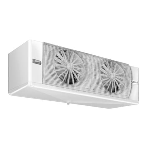
LU-VE CDH Series Technical specifications

CDH
Istruzione
per
il
montaggio
e
la
manutenzione
per
“AEROEV
APORA
TORI
INDUSTRIALI
A
DOPPIO
FLUSSO
Installation
and
maintenance
instruction
for
“DUAL
DISCHARGE
INDUSTRIAL
UNIT
COOLERS”.
I
T
A
L
I
A
N
O
E
N
G
L
I
S
H
F R A N C A I S
D E U T S C H
P O L S K I
Instruction
pour
le
montage
et
l’entretien
pour
“E
V
APOR
A
TEURS
VENTILES
INDUSTRIELS
DOUBLE
FLUX”.
Montage
und
wartungsanleitung
für
“INDUSTRIE
ZWEISEITIG
AUSBLASENDE
HOCHLEISTUNGSLUFTK
Ü
HLER”.
Instrukcja instalacji, eksploatacji i konserwacji dla
„
CHŁODNIC PRZEMYSŁOWYCH Z DWUSTRONNYM WYRZUTEM
POWIETRZA”
1

I T
A L I A N O
D i c h i a r a z i o n e
d e l
f a b b r i c a n t e .
N O R M E
-
Gli
apparecchi
sono
stati
pr
ogettati
e
costruiti
per
poter
essere
incorporati
in
macchine
co-
me
definito
dalla
Dir
ettiva
Macchine
2006/42CE
e
successivi
emendamenti.
•
EN
60335-1
(CEI
61-50)
Sicurezza
degli
apparecchi
elettrici
d’uso
domestico
e
similare.
Norme
Generali.
•
Dir
ettiva
2004CE
e
successivi
emendamenti.
Compatibilità
elettromagnetica.
•
Bassa
tensione
-
Riferimento
Dir
ettiva
2006/95CE
-
EN
294
Griglie
di
pr
otezione
T
uttavia
non
è
ammesso
metter
e
i
nostri
prodotti
in
funzione
prima
che
la
macchina
nella
quale
essi
sono
incorporati
o
della
quale
essi
sono
una
parte
sia
stata
dichiarata
conforme
alla
legislazione
in
vi
-
gore.
PRECAUZIONI:
Messa
in
guardia
contr
o
eventuali
rischi
d’infortunio
o
di
danneggia-
mento
dei
materiali
in
caso
d’inosservanza
delle
istruzioni.
A)
Per
le
operazioni
di
movimentazione,
installazione
e
manutenzione,
è
obbligatorio:
1
-
Personale
abilitato
all’uso
dei
mezzi
di
movimentazione
(gru,
carr
ello
elevator
e,
etc.).
2
-
Uso
dei
guanti
di
pr
otezione.
3
-
Non
sostar
e
sotto
il
carico
sospeso.
B)
Prima
di
pr
ocedere
ai
collegamenti
elettrici,
è
obbligatorio:
1
-
Personale
abilitato.
2
-
Assicurarsi
che
il
circuito
elettrico
d’alimentazione
sia
aperto.
3
-
L’interruttor
e
del
quadr
o
generale
d’alimentazione
sia
lucchettato
in
posizione
di
aperto.
C)
Prima
di
pr
ocedere
ai
collegamenti
dei
collettori/distributori,
è
obbligatorio:
1
-
Personale
abilitato.
2
-
Assicurarsi
che
il
circuito
d’alimentazione
sia
chiuso
(assenza
di
pr
essione).
3
-
Durante
l’operazione
di
saldatura,
assicurarsi
di
indirizzare
la
fiamma
in
modo
da
non
investi-
re
la
macchina
(eventualmente
interporr
e
una
pr
otezione).
D)
SMALTIMENTO:
I
pr
odotti
LU-VE
sono
composti
da:
Materiali
plastici:
polistirolo,
ABS,
gomma.
Materiali
metallici:
ferr
o,
acciaio
inox,
rame,
alluminio
(eventualmente
trattati).
Per
i
liquidi
r
efrigeranti
seguire
le
istruzioni
dell’installator
e
dell’impianto.
E)
T
oglier
e
la
pellicola
trasparente
di
pr
otezione
dalle
parti
metalliche
verniciate.
E N G L I S
H
M A N U FA C T U R E R S
D E C L A R A
T I O N
O F
I N C O R P O R AT I O N .
S TANDADS
-
The
products
are
pr
ovided
for
incorporation
in
machines
as
defined
in
the
EC
Machine
Dir
ective
2006/42CE
and
subsequent
modifications.
•
Machine
Dir
ective
2004/108/CE
and
subsequent
modifications.
Electr
omagnetic
compatibility
.
•
Low
tension
-
Refer
ence
Dir
ective
2006/95/CE
-
EN
294
Fan
guar
ds.
However
it
is
not
allowed
to
operate
our
equipment
in
advance
befor
e
the
machine
incorporating
the
prod-
ucts
or
making
part
thereof
has
been
declared
conforming
to
the
EC
Machine
Dir
ective.
PRECAUTIONS:
Accidents
warning
to
personal
injury
or
equipment
damage
due
to
neg-
ligence
for
complying
to
instructions.
A)
For
moving
installing
and
maintenance
operations
it
is
mandatory
to
comply
as
fol-
lows:
1
-
Employ
authorized
personnel
only
for
using
moving
equipment
(cranes,
fork
elevators,
etc.).
2
-
W
earing
of
work
gloves.
3
-
Never
stop
below
a
suspended
load.
B)
Befor
e
to
pr
oceed
with
elestrical
wirings
it
is
mandatory
to
comply
as
follows:
1
-
Authorized
personnel
only
shall
be
employed.
2
-
M
ake
sur
e
the
power
line
circuit
is
open.
3
-
The
main
switch
on
the
general
power
panel
is
open
and
pad-locked
in
this
setting.
C)
Befor
e
to
pr
oceed
with
the
collectors/distributors
connections
it
is
mandatory
to
comply
as
follows:
1
-
Authorized
personnel
only
shall
be
employed.
2
-
M
ake
sur
e
the
supply
circuit
is
closed
(no
pr
essur
e).
3
-
When
performing
welding
operations,
make
sur
e
the
flame
nozzle
is
not
aimed
towar
d
the
equipment
(insert
a
shield
if
r
equir
ed).
D)
DISPOSAL:
LU-VE
pr
oducts
ar
e
made
of:
Plastic
materials
:
polyethylene,
ABS,
rubber
.
Ferrous
materials
:
ir
on,
stainless
steel,
copper,
aluminium
(possibly
pr
ocessed).
Refrigerants
liquids
:
follow
the
instructions
relevant
to
the
equipment
installation.
E)
Remove
the
transparent
protection
film
fr
om
varnished
metallic
parts.
F R A N C A I
S
Declaration
d’incorporation
du
constructeu
r
.
NORMES
-
Les
pr
oduits
sont
conçus
et
costruits
pour
pouvoir
êtr
e
incorporés
dans
les
machines
comme
défini
par
la
directive
eur
opéenne
2006/42CE
et
amendements
successifs.
•
Dir
ective
2004/108/CE
et
amendements
successifs.
Compatibilité
électromagnétique.
•
Basse
tension
-
Référ
ence
Dir
ective
2006/95CE
-
EN
294
Grilles
de
pr
otection.
T
outefois,
il
n’est
pas
admis
de
mettr
e
nos
pr
oduits
en
fonctionnement
avant
que
la
machine
dans
la-
quelle
ils
sont
incorporés
ou
de
laquelle
ils
sont
une
partie,
ne
soit
considérée
et
déclarée
conforme
à
la
législation
en
vigueur
incluant
les
pr
oduits
objet
de
cette
déclaration.
PRECAUTIONS:
Mise
en
garde
contr
e
d’éventuels
risques
d’accident
ou
d’endommage-
ment
des
appar
eils
en
cas
de
non-observation
des
instrustions.
A)
Pour
les
opérations
de
manutention,
installation
et
maintenance,
est
obligatoir
e:
1
-
L’intervention
d’
un
opérateur
autorisé
à
l’
usage
des
appar
eils
de
manutention
(grue,
chariot
élévateur
,
etc.).
2
-
L’utilisation
des
gants
de
pr
otection.
3
-
De
ne
pas
stationner
en
dessous
d’une
charge
suspendue.
B)
A
vant
de
pr
océder
aux
raccor
dements
électriques,
est
obligatoir
e:
1
-
L’intervention
d’un
opérateur
autorisé.
2
-
De
s’assur
er
que
le
circuit
électrique
d’alimentation
est
ouvert.
3
-
De
s’assur
er
que
l’interrupteur
du
boîtier
général
d’alimentation
est
bloqué
par
un
cadenas
en
position
ouverte.
C)
A
vant
de
pr
océder
aux
raccor
dements
des
collesteurs/distributeurs,
est
obligatoi-
re
:
1
-
L’intervention
d’un
opérateur
autorisé.
2
-
De
s’assur
er
que
le
circuit
d’alimentation
est
fermé
(absence
de
pr
ession).
3
-
Durant
la
soudure,
de
veiller
à
diriger
la
flamme
de
façon
à
ne
pas
toucher
la
machine
(éventuellement,
il
conviendra
de
placer
une
pr
otection
devant
la
machine).
D)
ELIMINATION:
Les
pr
oduits
LU-VE
sont
composés
de:
Matériaux
plastiques:
Polystyrène,
ABS,
caoutchouc.
Matériaux
métalliques:
fer
,
acier
inox,
cuivre,
aluminium
(éventuellement
traité).
Pour
les
liquides
de
r
e
fr
oidissement,
suivre
les
instructions
de
l’installateur
de
l’appar
eil.
E)
Ôter
la
pellicule
transparente
de
protection
des
parties
métalliques
peintes.
D E U T S C
H
HERSTELLER
-
ERKL
Ä
RUNG
NORMEN
-
Die
Pr
odukte
sind
in
Überreistimmung
mit
der
EG
Richtlinie
2006/42CE
und
nachtfolgende
Ergänzungen
entwickelt,
konstruiert
und
gefertigt.
•
Richtlinie
2004/108/CE
und
nachfolgende
Ergänzungen.
Elektr
omagnetische
Kompatibilität.
•
Niederspannung
-
Richtlinie
2006/95/CE
-
EN
294
Schutzgitter.
Die
Inbetriebnahme
dieser
Maschine
ist
so
lange
untersagt,
bis
sichergestellt
ist,
daß
die
Anlage,
in
die
sie
eingebaut
wurde
oder
von
welcher
sie
ein
T
e
il
ist,
den
Bestimmungen
der
EG
Richtlinie
Maschinen
ent-
spricht.
VORSICHTSMASSNAHMEN:
W
arnung
vor
Unfall-
oder
Materialschadensgefahren
bei
V
orletzung
der
V
orschriften.
A)
Für
den
Innerbetrieblichen
T
ransport,
die
Installation
und
die
W
a
rtung
müssen
folgende
V
orschriften
eingehalten
wer
den:
1
-
Das
Personal
muß
für
die
Bedienung
von
innerbetrieblichen
T
ransporteinrichtungen
(Krane,
Hubkarr
en
usw
.)
befähigt
sein.
2
-
Gebrauch
von
Schutzhandschuhen.
3
-
Kein
Aufenthalt
von
Personen
unter
hängenden
Lasten.
B)
V
or
Ausführung
der
Elektr
oanschlüsse
müssen
folgende
V
orschriften
eingehalten
wer
den:
1
-
Fachkundiges
Personal.
2
-
Sicherstellen,
daß
der
Stromversorgungskr
eis
of
fen
ist.
3
-
Der
Schalter
am
Hauptstromversorgungs-Schaltschrank
muß
mit
einem
Schloß
versehen
und
geöffnet
sein.
C)
V
or
Anschluss
der
Sammelr
ohr
e/V
erteilerr
ohr
e
müssen
folgende
V
orschriften
ein-
gehalten
wer
den:
1
-
Fachkundiges
Personal.
2
-
Sicherstellen,
daß
der
Speisungskr
eis
geschlossen
ist
(kein
Druck).
3
-
B
eim
Schweißen
die
Flamme
so
ausrichten,
daß
die
Maschine
nicht
getrof
fen
wir
d
(eventuell
mit
einem
Schutz
versehen).
D)
ENTSORGUNG:
Die
LU-VE-Pr
odukte
bestehen
aus:
Plastmaterialien
:
Polystyrol,
ABS,
Gummi.
Metallmaterialien
:
Eisen,
r
ostfr
eier
Stahl,
Kupfer
,
Aluminium
(eventuell
behandelt).
Bezüglich
der
Kühlflüssigkeiten
sind
die
V
orschriften
des
Anlageninstallateurs
zu
beachten.
E)
Die
transparente
Plastfolie
von
den
lackierten
Metallteilen
entfernen.
POLSKI DEKLARACJA PRODUCENTA
Dokument referencyjny: EC Dyrektywa Maszynowa 2006/42/CE wraz z późniejszymi
zmianami.
Urządzenia zostały zaprojektowane i skonstruowane tak, aby mogły byćzastosowane w
maszynach według Dyrektywy Maszynowej 2006/42/CE (wraz z późniejszymi zmianami) i
odpowiadająnastępującym normom:
•Dyrektywa PED 97/23/CE
•Dyrektywa 204/108/CE i jej późniejsze zmiany – Kompatybilność elektromagnetyczna.
•Dyrektywa 2006/95/CE – Niskie napięcia
Jednakże niedopuszczalna jest praca urządzeńLU-VE Contardo jako części składowych
systemu lub maszyny, która jest niezgodna z DyrektywąMaszynowąEC.
OSTRZEŻENIA: Nieprzestrzeganie zaleceńzawartych w niniejszej instrukcji grozi
wypadkiem przy pracy z urządzeniami, uszkodzeniami ciała i zniszczeniem urządzeń.
A) Transport urządzeń, ich montażi obsługa:
1– Obsługa wyspecjalizowanego sprzętu typu dźwig, podnośnik powinna byćpowierzona
wyłącznie przeszkolonemu personelowi.
2– Wymagane jest stosowanie zabezpieczeńbudowlanych typu rękawice, kaski itp.
3– Zabronione jest przebywanie pod urządzeniami podnoszonymi przez dźwig.
B) Wykonywanie połączeńelektrycznych:
1– Prace elektryczne mogąbyćwykonywane wyłącznie przez wyspecjalizowany personel
2– Należy upewnićsię, że zasilanie główne obiegu elektrycznego jest wyłączone w wyłącznik
jest zabezpieczony przed przypadkowym załączeniem.
C) Podłączenie rurociągów:
1- Prace instalacyjne mogąbyćwykonywane wyłącznie przez wyspecjalizowany personel
2– Należy upewnićsię, że podłączany rurociąg jest opróżniony lub odcięty od instalacji (nie
pozostaje pod
ciśnieniem)
3– Należy zachowaćszczególnąostrożność przy spawaniu i nie dopuścićdo kontaktu
płomienia z urządzeniem.
D) Utylizacja urządzenia:
Materiały plastikowe: polietylen, ABS, guma
Materiały metalowe: stal, stal nierdzewna, miedź, aluminium
Czynniki chłodnicze: należy stosowaćsiędo instrukcji dostawcy urządzeńchłodniczych
E) Części metalowe lakierowane sąchronione na czas transportu i montażu
przezroczystąfolią
2

SOLLE
V
AMENTO
/
LIFTING
SKETCH
/
SOULEVEMENT
/
ANHEBEN
/
PODNOSZENIE W
POZ. PIONOWEJ
NO
-
NO
-
NON
NEIN
-
NIE
SI
-
YES
-
OUI
JA
-
TAK
•
Smontar
e
il
coperchio
“
1
”,
sollevar
e
la
cassa
al
sof
fitto
“
2
-
3
”usando
un
carrello
a
forche
facendo
passar
e
negli
appositi
fori
i
tiranti
di
sostegno”
4
”
.
Bloccar
e
i
dadi
dei
tiranti
di
sostegno
“
5
”
inter-
ponendo
una
rondella
di
bloccaggio.
T
oglier
e
i
bulloni
“
6
”.
Abbassar
e
la
cassa“
7
”.
•
Lift
the
crate
to
the
ceiling
“
1
”,
pr
eferably
by
use
of
forklift
truck
“2-3”.
Feed
securing
coach
bolts
through
pr
oper
holes
in
the
supporting
bars
of
the
unit
cooler
”
4
”.
Secur
ely
tighten
the
nuts
on
th-
rough
bolts
“
5
”,
interposing
a
washer.
Remove
bolts
“
6
”.
Lower
empty
crate
“
7
”.
•
Enlever
ensuite
le
couvercle
“
1
”,
élever
la
caisse
au
plafond
“
2
-
3
”,
au
moyen
d’un
char
ot
éléva-
teur,
et
placer
les
tirants
d’appui
dans
les
tr
ous
appropriés
”
4
”.
Serrer
les
écrous
des
tirants
d’ap-
pui
“
5
”en
y
interposant
une
rondelle
di
fixation.
Enlever
les
boulons
“
6
”.
Baisser
la
caisse
“
7
”.
•
Der
V
erschlag
ist
mit
Hilfe“
1
”
eines
Hubstaplers
zur
Dekke
zu
heben
“
2
-
3
”.
Die
Bolzen
für
die
Be-
festigung
sind
durch
die
entsprechenden
Löcher
der
Kühleraufhängung
zu
führ
en”
4
”.
Die
Muttern
“
5
”
sind
unter
V
erwendung
einer
Beilagscheibe
festzuziehen.
Die
Bolzen
“
6
”
sind
zu
entfernen.
Der
leere
verschlag
ist
herabzulassen
“
7
”.
•
Usunaćosłonę“1”, podnieść skrzyniędo sufitu “2-3” przy użyciu wózka widłowego,
mocując szpilki w odpowiednich otworach „4”. Zablokowaćnakrętki szpilek „5”
wstawiając pdokładkęblokująca. Usunąć śruby „6”, opuścićskrzynię„7”.
5
•
È
importante
che
l’apparecchio
sia
sistemato
in
modo
da
lasciare
uno
spazio
laterale
pari
alla
sua
lun-
ghezza.
Ciò
per
consentir
e
l’eventuale
sostituzione
delle
r
esistenze
elettriche
(ES)
.
•
It’
s
important
that
the
unit
cooler
is
installed
so
as
to
leave
space
to
the
left
of
cooler
(i.e.
facing
fans)
for
(ES)
electric
heaters
removal.
•
Il
est
important
de
noter
que
l’appar
eil
de-
vra
toujours
êtr
e
installé
avec
un
espace
latéral
lib
r
e
égal
a
sa
longueu
r
,
ceci
pour
6
6
l’eventue
l
r
emplacemen
t
de
s
résistance
électriques
(ES
).
•
Die
V
e
rdampfer
müssen
mit
einem
Seite-
nabstand,
der
genauso
Groß
ist
wie
die
Ve
rdampfer
lang
sind,
montiert
werde,
um
den
Austausch
der
Abtauheizstäbe
zü
gewährleisten
(ES)
.
•
Ważne jest, aby urządzenie zostało zamontowane
w taki sposób, aby było wolne miejsce z boku na całąjego długość
Pozwala to na ewentualnąwymianęgrzałek elektrycznych (ES)
6
7
6
6
INSTALLAZIONE
/
INST
ALLA
TION
/
INST
ALLA
TION
/
MONT
AGE
/
MONTAŻ
A
Modello
-
T
ype
-
Mod
è
le
-
Modell
Model
Elett
r
oventilatori
-
Fans
motor
-
V
entilateurs
V
entilator
en
-
Wentylatory
n°
1
2
3
4
A
mm
1250 2050 2850 3650
1”1/4
GAS
30
x
20
CD45H
B
mm
800
1600
2400
3200
C
mm
–
-
800 1600
D
mm
1355 1355 1355 1355
A
mm
1650 2850 4050 5250
CD63H
B
mm
1200 2400 3600 4800
CD64H
C
mm
–
-
1200 2400
D
mm
1775 1775 1775 1775
CD45H
225
C
B
225
D
CD63
-
64H
1”1/4
GAS
3
D
395
475
2000
mim.

A
T
T
ACCHI
/
CONNECTIONS
/
RACCORDS
/
ANSCHL
Ü
SSE
/
PRZYŁĄC
ZA
NO
-
NO
-
NON
NEIN
-
NIE
SI
-
YES
-
OUI
JA
-
TAK
•
Prima
di
p
r
ocede
r
e
ai
collegamenti
dei
collettori/distributori,
è
obbligatorio:
assicurarsi
che
il
cir
-
cuito
d’alimentazione
sia
chiuso
(assenza
di
pr
essione).
Durante
l’operazione
di
saldatura,
assicurarsi
di
indirizzar
e
la
fiamma
in
modo
da
non
investir
e
la
macchina
(eventualmente
interporr
e
una
pr
otezione).
•
Before
to
proceed
with
the
collectors/distributors
connections
it
is
mandatory
to
comply
as
follows:
Make
sur
e
the
supply
cir
c
uit
is
closed
(no
pr
essure).
When
performing
welding
operations,
make
sur
e
the
flame
nozzle
is
not
aimed
towar
d
the
equipment
(in-
sert
a
shield
of
requir
ed).
•
A
vant
de
proc
é
der
aux
raccordements
des
collesteurs/distributeurs,
est
obligatoir
e:
De
s’assur
er
que
le
cir
cuit
d’alimentation
est
ferm
é
(absence
de
pr
ession).
Durant
la
soudur
e,
de
veiller
à
diriger
la
flamme
de
façon
à
ne
pas
toucher
la
machine
(éventuellement,
il
conviendra
de
placer
une
pr
otection
devant
la
machine).
•
V
or
Anschluss
der
Sammelr
ohr
e/V
erteilerr
ohr
e
m
ü
ssen
folgende
V
orschriften
eingehalten
wer
den:
•
Non
adatta
r
e
la
posizione
dei
collettori
alla
linea.
•
Do
not
adapt
headers
position
to
the
suction
line
•
Ne
pas
adapter
la
position
du
collecteurs
à
la
ligne.
•
Sammlerposition
nicht
an
Leitung
anpassen
!
•
Nie wolno doginaćkolektorów wymienników. Pozycja
rurociągów powinna byćdostosowana do kolektorów.
Sicherstellen,
daß
der
Speisungsk
r
eis
geschlossen
ist
(kein
Druck).
Beim
Schweißen
die
Flamme
so
ausrichten,
daß
die
Maschine
nicht
getr
of
fen
wir
d
(eventuell
mit
einem
Schutz
versehen).
•
Przed rozpoczęciem wykonywania podłączenia rurociągów (kolektorów/ rozdzielaczy)
obowiązkowo należy:
• upewnićsię, że podłączony rurociąg jest opróżniony lub odcięty od instalacji (nie pozostaje pod
ciśnieniem).
• Zadbać, aby płomieńspawania nie był skierowany w stronęurządzenia (ewentualnie
zastosowaćosłonęognioodporną).
COLLEGAMENT
I
/
CONNECTION
S
/
RACCORDEMENT
S
/
ANSCHL
Ü
SS
E
/
PRZYŁĄCZA
•
COLLEGAMENTO
TUBAZIONI
SCARICO
ACQUA
:
avvita
r
e
allo
scarico
delle
ba
-
cinelle
un
gomito
a
60°
(
A
).
È
necessario
che,
sia
la
valvola
solenoide
che
l’eventuale
rubinetto
a
mano
per
il
co
-
mando
della
mandata
dell’acqua,
siano
installati
all’esterno
della
cella,
ad
un
livello
più
basso
dell’evaporator
e.
Su
questa
linea
verrà
installato
inoltr
e
un
(
T
),
all’estr
emità
del
quale
si
collegherà
un
tubetto
disperdente
che
servirà
a
mantener
e
scarico
il
trat
-
to
di
tubazione
che
va
dalla
solenoide
all’evaporatoe
per
evitar
e
il
congelamento
del
-
l’acqua.
•
W
A
TER
DRAIN
TUBING
CONNECTION
:
fit
a
60°
elbow
(
A
),
to
the
drain
tra
y
.
It’
s
essential
that
the
contr
ol
valve,
either
hand
or
automatic,
be
fitted
outside
the
cold
room
and
at
a
lower
level
than
the
evaporator,
and
a
drain
off
(
TEE
)
piece
should
be
fitted
with
a
bleed
tube
to
allow
water
left
in
the
feed
pipe
to
the
cooler
to
drayn
away
when
the
contr
ol
valve
close.
•
CONNECTION
TUBE
É
V
ACUA
TION
D’EAU
:
visser
e
une
coude
filetée
de
60°
(
A
)
a
la
sortie
des
egout-
toirs.
La
vanne
solénoide
et
éventuellement
la
vanne
à
main
pour
la
commande
de
l’eau
ser
ont
installées
a
l’extérieur
de
la
chambr
e
froide
à
un
nuveau
plus
bas
que
celui
de
l’évaporateur.
On
installera
en
outr
e
sur
cette
conduite
un
(
T
)
à
l’extrémité
duquel
un
tube
déperditeur
servira
de
vidange
à
la
partie
de
la
condui-
te
située
entr
e
la
vanne
solenoide
et
l’évaporateur;
ceci
pour
eviter
le
danger
de
gel
de
l’eau.
•
TROPFWASSERANSCHLUSS
:
montier
e
einen
60°
Bogen
(
A
).
Es
ist
wichtig,
dass
das
Wasser
-Regel-Ventil
(hand
oder
automatisch)
ausserhalb
del
Kühlraums
un
Tie-
fer
als
der
V
e
rdampfer
installiert
wir
d
und
dass
ein
T
-Stück,
wie
nachstehend
abgebildet,
eingebaut
wir
d,
der
eine
abzweig
am
T
-Stück
sollte
stark
reduziert
sein,
sodass
wahrend
des
Abtauens
nur
wenig
Wa
s-
ser
ausfliessen
kann
und
sich
nach
schliessen
des
V
entils
die
W
asserzuleitung
entleer
en
kann.
•
Połączenie instalacji rurowej skroplin: zamontowaćkolanko 60° (A) do odpływu z tacy skroplin.
Istotne jest, aby zawór regulacyjny, ręczny lub automatyczny został zainstalowany na zewnątrz
komory oraz niżej niżparownik. Należy równieżzamontowaćelement zwrotny (T) wraz z
fragmentem rurki odpływowej, który umożliwi opróżnienie z wody linii zasilającej za zaworem
natychmiast po zamknięciu zaworu.
VERIFICH
E
/
COOLER
CA
P
ACITY
CHECKS
/
CONTROLES
/
LEISTUNGSUBERPRUFUN
G
/
TESTY
VERIFICHE
-
Rileva
r
e
le
seguenti
temperatu
r
e
e
p
r
essioni:
Ts
’
-
T
emperatura
di
cella
nella
zona
aria
ingresso
all’evaporator
e.
Te
-
T
emperatura
di
evaporazione,
corrispondente
alla
pr
essione
del
refrigerante
all’uscita
dell’eva-
porator
e.
Tr
s
-
T
emperatura
di
surriscaldamento
del
refrigerante,
sulla
linea
di
aspirazione
in
prossimità
del
bul-
bo
della
valvola
termostatica.
N.B.
-
Per
una
utilizzazione
ottimizzata
dell’evaporatore
il
surriscaldamento
(T
rs-T
e)
non
dovr
à
supera
r
e
0,7
x
(
T
s’
-
T
e).
•
CONTROLES
-
Relever
les
températu
r
es
et
p
r
essions
suivantes:
Ts
’
-
Témperature
de
la
chambr
e
froide
dans
la
zone
d’entrée
d’air
de
l’évaporateur
.
Te
-
Témperature
d’évaporation,
correspondante
à
la
pr
ession
du
réfrigérant
à
la
sortie
de
l’évapo-
rateur.
Tr
s
-
Témperature
de
sur
chauf
fe
du
réfrigérant,
sur
la
ligne
d’aspiration
à
proximité
du
bulbe
de
la
vanne
thermostatique.
N.B.
-
Pour
utiliser
l’a
é
ro
é
vaporateur
dans
les
conditions
optimales,
la
sur
chauffe
(T
rs-T
e)
ne
doit
pas
ê
t
r
e
sup
é
rieu
r
e
à
0,7
x
(
T
s’
-
T
e).
•
COOLER
CAPACITY
CHECKS
-
T
ake
the
following
temperatu
r
e
and
p
r
essu
r
es:
Ts
’
-
Cold
r
oom
air
inlet
temperatur
e
to
the
unit.
Te
-
Evaporating
temperatur
e,
relating
to
the
refrigerant
pr
essure
on
the
unit
cooler
outlet.
Tr
s
-
Refrigerant
superheat
temperatur
e,
on
suction
line
near
thermostatic
valve
bulb.
N.B.
-
For
otimum
unit
cooler
performance
the
superheat
(T
rs-T
e)
shoud
not
be
higher
than
0,7
x
(T
s’-T
e).
•
LEISTUNGSUBERPRUFUNG
-
Folgende
T
emperatu
r
en
und
Drücke
sind
zu
messen:
Ts
’
-
Kühlraumtemperatur
an
der
Lufteintrittsseite
des
V
er
dampfers.
Te
-
V
er
d
ampfungstemperatur
über
Druck
am
V
er
dampfer
ende.
Tr
s
-
Fühlertemperatur
an
der
Saugleitung
nahe
beim
Fühler
des
Expansionventils.
N.B.
-
F
ü
r
eine
optimale
V
erdampferarbeitsweise
darf
die
Ü
berhitzung
(T
rs-T
e)
nicht
h
ö
her
sein
als
0,7
x
(T
s’-T
e).
4
T
s
’
T
r
s
Te
•
KONTROLA PRACY CHŁODNICY
Należy dokonaćnastępujących pomiarów temp. i ciśnienia:
Ts’ – temp. powietrza w komorze po stronie wejściowej do parownika
Te - Temperatura, odpowiadająca ciśnieniu czynnika chłodniczego na wyjściu z
parownika
Trs - Temperatura przegrzania czynnika chłodniczego, na linii ssawnej w pobliżu
czujnika zaworu termostatycznego.
Uwaga: Dla optymalnej pracy parownika, przegrzanie (Trs-Te) nie powinno
przekraczać0,7 x (Ts’-Te).
Po upewnieniu się, że zawór termostatyczny jest prawidłowo zainstalowany i
dostosowany do warunków pracy danego systemu, należy utrzymaćjak najniższe
przegrzanie, aby zapewnićmaksymalnąwydajność parownika.

E
SBRINAMENTO
ELETTRICO
/
ELECTRIC
DEFROST
/
DEGIVRAGE
ELECTRIQUE
/
ELEKTRISCHE
AB
T
AUUNG
/
ROZMRAŻANIE ELEKTRYCZNE
CD45H
8100
-
4
8102
-
4
8104
-
4
8106
-
4
8108
-
4
8110
-
4
8112
-
4
8114
-
4
CD45H...E
CD45H
8200-6
8202-6
8204-6
8206-6
8208-6
8210-6
8212-6
8214-6
CD45H
8300-7
8302-7
8304-7
8306-7
8308-7
8310-7
8312-7
8314-7
Elett
r
ovent.
Fans
V
entilateurs
V
entilatoren
Wentylatory
n°
1
1
2
2
3
3
4
4
(1*)
N°
4
4
4
4
4
4
4
4
Batteria
Coil
Batterie
Block
Wymiennik
Bacinella
Drain
tray
Égouttoir
Tr
ofwanne
Taca
Mod.
/
Type
RCL8
RCL8
RCL16
RCL16
RCL24
RCL24
RCL32
RCL32
(
230
V
x
n°
1)
W
850
850
1585
1585
2300
2300
3020
3020
(2*)
N°
---
2
---
2
---
2
--
2
Mod.
/
Type
---
FCL8
---
FCL16
---
FCL24
---
FCL32
(230
V)
x
n°
1)
W
---
850
---
1585
---
2300
---
3020
TOT.
(1*+
2*)
=
W
3400
5100
6340
9510
9200
13800
12080
18120
(3*)
N°
2
2
2
2
2
2
2
2
Mod.
/
Type
FCL8
FCL8
FCL16
FCL16
FCL24
FCL24
FCL32
FCL32
(
230
V
x
n°
1)
W
850
850
1585
1585
2300
2300
3020
3020
(4*)
N°
1
1
1
1
1
1
1
1
Mod.
/
Type
EB1
EB1
EB1
EB1
EB1
EB1
EB1
EB1
(
230
V
x
n°
1)
W
200
200
200
200
200
200
200
200
T
O
T
.
(3*+
4*)
=
W
1900
1900
3370
3370
4800
4800
6240
6240
CD45H...E
TOT.
(1*+2*+3*+4*)
=
W
5300
7000
9710
12880
14000
18600
18320
24360
Schema
di
collegamento
/
Connection
wiring
/
Schema
de
raccor
dement
/
Schaltbilder
Zeichenerkl
ä
rung
/
Schemat elektryczny
01
02
01
02
01
02
01
02
Prim
a
d
i
p
r
ocede
r
e
a
i
collegament
i
elettrici
,
è
obbligatori
o
assicurarsi
che
il
ci
r
cuito
elettrico
d’alimentazione
sia
aperto.
Befor
e
to
proceed
with
electrical
wirings
it
is
mandatory
to
comply
as
follows
make
su-
re
the
power
line
circuit
is
open.
A
vant
de
proc
é
der
aux
raccordements
é
lectriques,
est
obligatoir
e
d
e
s’assur
er
que
le
ci
r
cuit
é
lectrique
d’alimentation
est
ouvert.
V
o
r
Ausf
ü
hrung
der
Elekt
r
o
anschl
ü
sse
m
ü
ssen
folgende
V
orschriften
eingehalten
wer
den
Sicherstellen,
daß
der
Stromversorgungskr
eis
offen
ist.
Przed rozpoczęciem wykonywania połączeńelektrycznych należy
obowiązkowo:
Upewnićsię, że zasilanie główne jest wyłączone.
Schema
di
collegamento
Connection
wiring
Schema
de
racco
r
dement
Schaltbilder
Zeichenerklärung
Schemat elektryczny
RCL
RCL
Z
X
Y
Z
X
Y
U1
V1
W1
FCL
FCL
EB1
U
V
W
U
V
W
U2
V2
W2
1
2
3
N
Schema
di
collegamento
Connection
wiring
Schema
de
racco
r
dement
Schaltbilder
Zeichenerklärung
Schemat elektryczny
S
T
ANDARD
3~400
V
50-60
Hz
RCL
FCL
FCL
RCL
Z
X
Y
Z
X
Y
U1
V1
W1
U
V
W
U2
V2
W2
U
V
W
3~230
V
50
-
60
Hz
FCL
FCL
EB1
5
Resistenze elettriche Electric heaters
Résistances électriques Heizstäbe
Grzałki elektryczne
01
02
EB1
FCL
FCL
RCL
RCL
RCL
RCL
EB1
FCL
FCL
FCL
FCL
RCL
RCL
RCL
RCL

E
SBRINAMENTO
ELETTRICO
/
ELECTRIC
DEFROST
/
DEGIVRAGE
ELECTRIQUE
/
ELEKTRISCHE
AB
T
AUUNG
/
ROZMRAŻANIE ELEKTRYCZNE
CD63H
8500
-
4
8502
-
4
---
8506
-
4
8508
-
4
---
8512
-
4
8514
-
4
---
8518
-
4
8520
-
4
---
CD63H...E
CD63H
8600
-
6
8602
-
6
8604
-
6
8606
-
6
8608
-
6
8610
-
6
8612
-
6
8614
-
6
8616
-
6
8618
-
6
8620
-
6
8622
-
6
CD63H
8700-7
8702-7
8704-7
8706-7
8708-7
8710-7
8712-7
8714-7
8716-7
8718-7
8720-7
8722-7
CD63H
8800-10
8802-10
8804-10
8806-10
8808-10
8810-10
8812-10
8814-10
8816-10
8818-10
8820-10
8822-10
CD64H
9000
-
4
9002
-
4
---
9006
-
4
9008
-
4
---
9012
-
4
9014
-
4
---
9018
-
4
9020
-
4
---
CD64H...E
Elettrovent.
Fans
V
entilateurs
CD64H
9100
-
6
9102
-
6
9104
-
6
9106
-
6
9108
-
6
9110
-
6
9112
-
6
9114
-
6
9116
-
6
9118
-
6
9120
-
6
9122
-
6
CD64H
9200-7
9202-7
9204-7
9206-7
9208-7
9210-7
9212-7
9214-7
9216-7
9218-7
9220-7
9222-7
CD64H
9300-10
9302-10
9304-10
9306-17
9308-10
9310-10
9312-10
9314-10
9316-10
9318-10
9320-10
9322-10
V
entilatoren
wentylatory
n°
1
1
1
2
2
2
3
3
3
4
4
4
(1*)
N°
4
4
8
4
4
8
4
4
8
---
---
---
Batteria
Coil
Batterie
Block
Wymiennik
Bacinella
Drain
tray
Égouttoir
Mod.
/
Type
RCL12
RCL12
RCL12
RCL24
RCL24
R
CL24
RCL36
RCL36
RCL36
---
---
---
(230
V
x
n°1)
W
1215
1215
1215
2300
2300
2300
3375
3375
3375
---
---
---
(2*)
N°
---
2
---
---
2
---
---
2
---
4
6
8
Mod.
/
Type
---
FCL12
---
---
FCL24
---
---
FCL36
---
FCL48
FCL48
FCL48
230
V
x
n°1)
W
---
1215
---
---
2300
---
---
3375
---
4450
4450
4450
TOT.
(1*+2*)
=
W
4860
7290
9720
9200
13800
18400
13500
20250
27000
17800
26700
35600
(3*)
N°
2
2
2
2
2
2
2
2
2
2
2
2
Mod.
/
Type
FCL12
FCL12
FCL12
FCL24
FCL24
FCL24
FCL36
FCL36
FCL36
FCL48
FCL48
FCL48
230
V
x
n°1)
W
1215
1215
1215
2300
2300
2300
3375
3375
3375
4450
4450
4450
(4*)
N°
1
1
1
1
1
1
1
1
1
1
1
1
T
r
ofwanne
Taca
Mod.
/
Type
EB1
EB1
EB1
EB1
EB1
EB1
EB1
EB1
EB1
EB1
EB1
EB1
230
V
x
n°1)
W
200
200
200
200
200
200
200
200
200
200
200
200
TOT.
(3*+4*)
=
W
2630
2630
2630
4800
4800
4800
6950
6950
6950
9100
9100
9100
CD...H
...E
TOT.
(1*+2*+3*+4*)
=
W
7490
9920
12350
14000
18600
23200
20450
27200
33950
26900
35800
44700
Schema
di
collegamento
/
Connection
wiring
/
Schema
de
raccor
dement
/
Schaltbilder
Zeichenerkl
ä
rung
/
S
chemat elektryczny
01
02
03
01
02
03
01
02
03
04
05
06
Prim
a
d
i
p
r
ocede
r
e
a
i
collegament
i
elettrici
,
è
obbligatori
o
assicurar
-
si
che
il
circuito
elettrico
d’alimentazione
sia
aperto.
Befor
e
to
proceed
with
electrical
wirings
it
is
mandatory
to
comply
as
follows
make
sur
e
the
power
line
circuit
is
open.
A
vant
de
proc
é
der
aux
raccordements
é
lectriques,
est
obliga
-
toir
e
d
e
s’assur
er
que
le
circuit
é
lectrique
d’alimentation
est
ou
-
vert.
V
o
r
Ausf
ü
hrung
der
Ele
kt
r
oanschl
ü
sse
m
ü
ssen
folgende
V
orsch
-
riften
eingehalten
wer
den
Sicherstellen,
daß
der
Stromversor
-
gungskr
eis
offen
ist.
Przed rozpoczęciem wykonywania połączeńelektrycznych
należy obowiązkowo:
Upewnićsię, że zasilanie główne jest wyłączone.
Z
X
Y
U1
V1
W1
U
V W
U2
V2
W2
1
2
3
N
Schema
di
collegamento
Connection
wiring
Schema
de
raccordement
RCL
RCL
Schaltbilder
Zeichenerklärung
Schemat elektryczny
Z
X
01
Y
S
T
ANDARD
3~400
V
50-60
Hz
Z
X Y
U1
V1
W1
FCL
FCL
EB1
U
V
W
U
V
W
U2
V2
W2
3~230
V
50-60
Hz
Schema
di
collegamento
Connection
wiring
Schema
de
raccordement
RCL
FCL
FCL
RCL
S
chaltbilder
Zeichenerklärung
Schemat elektryczny
Schema
di
collegamento
Connection
wiring
Schema
de
raccordement
RCL
RCL
Schaltbilder
Zeichenerklärung
Schemat elektryczny
03
Z
X
Y
Z
X
Y
FCL
FCL
EB1
U
V
W
FCL
FCL
EB1
U
V
W
Schema
di
collegam
ento
Connection
wiring
Schema
de
raccordement
FCL
FCL
FCL
FCL
EB1
Schema
di
collegamento
Connection
wiring
Schema
de
raccordement
FCL
FCL
Schaltbilder
Zeichenerklärung
Schemat elektryczny
Z
X
U
V
Schaltbilder
Zeichenerklärung
Schemat elektryczny
04
W
05
Y
solo
per:
Only
for:
Seulement
pour:
Nur
für:
Tylko dla
:
Schema
di
collegamento
Connection
wiring
Schema
de
raccordement
FCL
FCL
CD63H
8518
-
4
8520
-
4
---
CD63H
8618-6
8620-6
8622-6
CD63H
8718-7
8720-7
8722-7
CD63H
8818-10
8820-10
8822-10
CD64H
9018-4
9020-4
---
CD64H
9118-6
9120-6
9122-6
CD64H
9218-7
9220-7
9222-7
CD64H
9318-10
9320-10
9322-10
Schaltbilder
Zeichenerklärung
Schemat elektryczny
Z
X
Y
Z
X
Y
6
FCL
FCL
EB1
U
V
W
FCL
FCL
EB1
U
V
W
02
Resistenze elettriche Electric heaters
Résistances électriques Heizstäbe
Grzałki elektryczne
EB1
FCL
FCL
RCL
RCL
RCL
RCL
EB1
FCL
FCL
FCL
RCL
RCL
RCL
RCL
RCL
EB1
FCL
FCL
RCL
RCL
RCL
RCL
RCL
RCL
RCL
RCL
EB1
FCL
FCL
RCL
FCL
FCL
FCL
EB1
FCL
FCL
FCL
FCL
FCL
FCL
FCL
FCL
EB1
FCL
FCL
FCL
FCL
FCL
FCL
FCL
FCL
FCL
FCL

G
SBRINAMENTO
MISTO
GAS
CALDO
-
ELETTRICO
HOT
GAS
-
ELECTRIC
MIXED
DEFROS
DEGIVRAGE
MIXTE
GAZ
CHAUD-ELECTRIQUE
HEIßGAS-ELEKTRISCHE
GEMISCHT
ABT
AUUNG
ROZMARAŻANIE MIESZANE CIEPŁYM GAZEM-ELEKTRYCZNE
CD45...G
8100
-
4
8102
-
4
8104
-
4
8106
-
4
8
108
-
4
8110
-
4
8112
-
4
8114
-
4
---
---
---
---
CD45H...G
CD45...G
8200-6
8202-6
8204-6
8206-6
8208-6
8210-6
8212-6
8214-6
---
---
---
---
CD45...G
8300-7
8302-7
8304-7
8306-7
8308-7
8310-7
8312-7
8314-7
---
---
---
---
Elettrovent. Fans
Ventilateurs
Ventilatoren wentylatory.
n°
1 1 2 2 3 3 4 4
Attacchi Connect. Raccords
Anschlüsse Przyłącza
Ø
A/B
mm
16/28
16/28
16/42
6/42
6/42
28/64
28/54
28/64
---
---
---
---
(1*)
N°
2
2
2
2
2
2
2
2
---
---
---
---
Resistenza
elettrica
Electric
heater
Résistance
électrique
Heizstäbe
T
ropfwanne
Grzałki elektr.
Mod.
/
Type
FCL8
FCL8
FCL16
FCL16
FCL24
FCL24
FCL32
FCL32
---
---
---
---
(230
V)
x1
=
W
850
850
1585
1585
2300
2300
3020
3020
---
---
---
---
(2*)
N°
1
1
1
1
1
1
1
1
---
---
---
Mod.
/
Type
EB1
EB1
EB1
EB1
EB1
EB1
EB1
EB1
---
---
---
---
(
230
V
x
n°
1)
W
200
200
200
200
200
200
200
200
---
---
---
---
CD45H...G
TO
T
.
(1*+2*)
=
W
1900
1900
3370
3370
48
00
4800
6240
6240
---
---
---
---
CD63...G
8500
-
4
8502
-
4
---
8506
-
4
8508
-
4
---
8512
-
4
8514
-
4
---
8518
-
4
8520
-
4
---
CD63H...G
CD63...G
8600-6
8602-6
8604-6
8606-6
8608-6
8610-6
8612-6
8614-6
8616-6
8618-6
8620-6
8622-6
CD63...G
8700-7 8702-7 8704-7 8706-7 8708-7 8710-7 8712-7 8714-7 8716-7 8718-7 8720-7 8722-7
CD63...G
8800-10
8802-10
8804-10
8806-10
8808-10
8810-10
8812-10
8814-10
8816-10
8818-10
8820-10
8822-10
CD64...G
9000-4
9002-4
---
9006-4
9008-4
---
9012-4
9014-4
---
9018-4
9020-4
---
CD64H...G
Elettrovent.
Fans
V
entilateurs
CD64...G
9100
-
6
9102
-
6
9104
-
6
9106
-
6
9108
-
6
9110
-
6
9112
-
6
9114
-
6
9116
-
6
9118
-
6
9120
-
6
9122
-
6
CD64...G
9200-7
9202-7
9204-7
9206-7
9208-7
9210-7
9212-7
9214-7
9216-7
9218-7
9220-7
9222-7
CD64...G
9300-10
9302-10
9304-10
9306-17
9308-10
9310-10
9312-10
9314-10
9316-10
9318-10
9320-10
9322-10
V
entilatoren
W
entyatory.
n°
1
1
1
2
2
2
3
3
3
4
4
4
Anschlüsse
Przyłącza
Ø
A/B
mm
16/35
16/42
28/54
28/54
28/54
35/76
28/64
35/76
35/89
3
5/89
3
5/89
35/89
Resistenza
elettrica
Electric
heater
Résistance
électrique
Heizstäbe
T
ropfwanne
Grzałki elektr.
(1*)
N°
2
2
2
2
2
2
2
2
2
2
2
2
Mod.
/
Type
FCL12
FCL12
FCL12
FCL24
FCL24
FCL24
FCL36
FCL36
FCL36
FCL48
FCL48
FCL48
(230
V)
x1
=
W
1215
1215
1215
2300
2300
2300
3375
3375
3375
4450
4450
4450
(2*)
N°
1
1
1
1
1
1
1
1
1
1
1
1
Mod.
/
Type
EB1
EB1
EB1
EB1
EB1
EB1
EB1
EB1
EB1
EB1
EB1
EB1
(230
V
x
n°1)
W
200
200
200
200
200
200
200
200
200
200
200
200
CD63H/64H...G
TO
T
.
(1*+2*)
=
W
2630
2630
2630
4800
4800
4800
6950
6950
6950
9100
9100
9100
Prim
a
d
i
p
r
ocede
r
e
a
i
collegament
i
elettrici
,
è
obbligatori
o
assicurarsi
che
il
ci
r
cuito
elettrico
d’alimentazione
sia
aperto.
Befor
e
to
proceed
with
electrical
wirings
it
is
mandatory
to
comply
as
follows
make
su-
re
the
power
line
circuit
is
open.
A
vant
de
proc
é
der
aux
raccordements
é
lectriques,
est
obligatoir
e
d
e
s’assu-
r
er
que
le
ci
r
cuit
é
lectrique
d’alimentation
est
ouvert.
V
o
r
Ausf
ü
hrung
der
Elekt
r
oanschl
ü
sse
m
ü
ssen
folgende
V
o
rschriften
eingehalten
wer
den
Sicherstellen,
daß
der
Stromversorgungskr
eis
offen
ist.
Przed rozpoczęciem wykonywania połączeńelektrycznych należy
obowiązkowo:
Upewnićsię, że zasilanie główne jest wyłączone.
FCL
EB1
FCL
Ø
A
Ø
B
COLLEGAMENTO
RESISTENZA
HEA
TER
CONNECTION
CONNEXION
RESISTANCE
ANSCHL
Ü
SSE
PODŁĄCZENIE GRZAŁKI
1
2
3
N
Z
X
U
V
S
T
ANDARD
Y
W
3~400
V
50
-
60Hz
AT
TACCHI
/
CONNECTIONS
/
RACCORDS
/
ANSCHL
Ü
SSE
/
PRZYŁĄCZA
NO
-
NO
-
NON
NEIN
-
NIE
NO
-
NO
-
NON
NEIN
-
NIE
SI
-
YES
-
OUI
JA
-
TAK
SI
-
YES
-
OUI
JA
-
TAK
7
SI
-
YES
-
OUI
JA
-
TAK
NO
-
NO
-
NON
NEIN
-
NIE
EB1
FCL
FCL
EB1
FCL FCL

GB
SBRINAMENT
O
A
GA
S
CALD
O
NELL
A
B
A
TTERI
A
E
BACINELL
A
COI
L
AN
D
DRAIN
-
TR
A
Y
HO
T
GA
S
DEFROST
DEGIVRAGE
A
GAS
CHAUD
DANS
LA
BA
TTERIE
ET
L
’EGOUTTOIR
HEIßGASABTAUUNG
DER
BA
TTERIE
UND
TROPFWANNE DR
ROZMRAŻANIE CIEPŁYM GAZEM W WYMIENNIKU I TACY
CD45...GB
8100
-
4
8102
-
4
8104
-
4
8106
-
4
8108
-
4
8110
-
4
8112
-
4
8114
-
4
---
---
---
---
CD45H...GB
CD45...GB
8200-6
8202-6
8204-6
8206-6
8208-6
8210-6
8212-6
8214-6
---
---
---
---
CD45...GB
8300-7
8302-7
8304-7
8306-7
8308-7
8310-7
8312-7
8314-7
---
---
---
---
Elettrovent. Fans Ventilateurs
Ventilatoren Wentylatory n° 1 1 2 2 3 3 4 4 ---- ---- ---- ----
Attacchi Connect. Raccords
Anschlüsse
P
rzył cza
Ø G mm
28 28
28 28 28 28
28
28
--
---
---
---
Ø
G
Ø
G
Ø
G
CD63...GB
8500
-
4
8502
-
4
---
8506
-
4
8508
-
4
--
-
8512
-
4
8514
-
4
---
8518
-
4
8520
-
4
---
CD63H...G
CD63...GB
8600-6
8602-6
8604-6
8606-6
8608-6
8610-6
8612-6
8614-6
8616-6
8618-6
8620-6
8622-6
CD63...GB
8700-7
8702-7
8704-7
8706-7
8708-7
8710-7
8712-7
8714-7
8716-7
8718-7
8720-7
8722-7
CD63...GB
8800-10
8802-10
8804-10
8806-10
8808-10
8810-10
8812-10
8814-10
8816-10
8818-10
8820-10
8822-10
CD64...GB
9000-4
9002-4
---
9006-4
9008-4
---
9012-4
9014-4
---
9018-4
9020-4
---
CD64H...G
Elettrovent.
Fans
V
entilateurs
CD64...G
B
9100
-
6
9102
-
6
9104
-
6
9106
-
6
9108
-
6
9110
-
6
9112
-
6
9114
-
6
9116
-
6
9118
-
6
9120
-
6
9122
-
6
CD64...GB
9200-7
9202-7
9204-7
9206-7
9208-7
9210-7
9212-7
9214-7
9216-7
9218-7
9220-7
9222-7
CD64...GB
9300-10
9302-10
9304-10
9306-17
9308-10
9310-10
9312-10
9314-10
9316-10
9318-10
9320-10
9322-10
V
entilatoren
Wentylatory
n°
1
1
1
2
2
2
3
3
3
4
4
4
Connect raccords
A
nschlüsse
P
rzyłącza
Ø
G
mm
28
28
28
28
28
28
35
35
35
35
35
35
8

ELETTROVENTIL
A
TORI
/
F
AN
MOTORS
/
VENTIL
A
TEURS
/
VENTIL
A
TOREN
/
WENTYLATORY
Modello
T
ype
Modèle
Modell
Model
Elettr
oventilator
Fans
V
entilateurs
V
entilator
en
CD45H
8100
-
4
8102
-
4
8104
-
4
8106
-
4
8108
-
4
8110
-
4
8112
-
4
8114
-
4
---
---
---
---
CD45H
8200-6
8202-6
8204-6
8206-6
8208-6
8210-6
8212-6
8214-6
---
---
---
---
CD45H
8300-7
8302-7
8304-7
8306-7
8308-7
8310-7
8312-7
8314-7
---
---
---
---
n°
1
1
2
2
3
3
4
4
---
---
---
---
Wentylatory
Mod.
/
Type
A4D450-AO14-02
(4P)
3~400
V
50/60 Hz
Assorbimento
motori
x
1
Motors
power
consumption
x
1
Puissance
moteur
x
1
Motorleistungaufnahme
x
1
Pobór mocy/prądu silnika
x1
S
T
ANDARD
OPTIONAL
3~400
V
50
H
z
N
=
455
W
1,0
A
M
=
...
W
...
A
S
=
...A
3~400
V
50
H
z
N
=
335
W
0,7
A
M
=
...
W
...
A
S
=
...A
3~400
V
60
H
z
N
=
...
W
...
A
M
=
...
W
...
A
S
=
...A
3~400
V
60
H
z
N
=
...
W
...
A
M
=
...
W
...
A
S
=
...A
Modello
T
ype
Modèle
Modell
Model
Elettr
oventilator
Fans
V
entilateurs
V
entilator
en
CD63H
8500
-
4
8502
-
4
---
8506
-
4
8508
-
4
---
8512
-
4
8514
-
4
---
8518
-
4
8520
-
4
---
CD63H
8600-6
8602-6
8604-6
8606-6
8608-6
8610-6
8612-6
8614-6
8616-6
8618-6
8620-6
8622-6
CD63H
8700-7
8702-7
8704-7
8706-7
8708-7
8710-7
8712-7
8714-7
8716-7
8718-7
8720-7
8722-7
CD63H
8800-10
8802-10
8804-10
8806-10
8808-10
8810-10
8812-10
8814-10
8816-10
8818-10
8820-10
8822-10
n°
1
1
1
2
2
2
3
3
3
4
4
4
Wentylatory
Mod.
/
Type
A6D630
-
AN01
-
02
(6P)
3~400
V
50/60
Hz
Assorbimento
motori
x
1
Motors
power
consumption
x
1
Puissance
moteur
x
1
Motorleistungaufnahme
x
1
Pobór mocy/prądu silnika
x1
S
T
ANDARD
OPTIONAL
3~400
V
50
H
z
N
=
590
W
1,3
A
M
=
...
W
...
A
S
=
...
A
3~400
V
50
H
z
N
=
400
W
0,7
A
M
=
...
W
...
A
S
=
A
3~400
V
60
H
z
N
=
...
W
...
A
M
=
...
W
...
A
S
=
A
3~400
V
60
H
z
N
=
...
W
...
A
M
=
...
W
...
A
S
=
A
Modello
T
ype
Modèle
Modell
Model
Elettr
oventilator
Fans
V
entilateurs
V
entilator
en
CD64H
9000
-
4
9002
-
4
---
9006
-
4
9008
-
4
---
9012
-
4
9014
-
4
---
9018
-
4
9020
-
4
---
CD64H
9100-6
9102-6
9104-6
9106-6
9108-6
9110-6
9112-6
9114-6
9116-6
9118-6
9120-6
9122-6
CD64H
9200-7
9202-7
9204-7
9206-7
9208-7
9210-7
9212-7
9214-7
9216-7
9218-7
9220-7
9222-7
CD64H
9300-10
9302-10
9304-10
9306-17
9308-10
9310-10
9312-10
9314-10
9316-10
9318-10
9320-10
9322-10
n°
1
1
1
2
2
2
3
3
3
4
4
4
Wentylatory
Mod.
/
Type
A4D630
-
AR05
-
02
(4P)
3~400
V
50/60
Hz
Assorbimento
motori
x
1
Motors
power
consumption
x
1
Puissance
moteur
x
1
Motorleistungaufnahme
x
1
Pobór mocy/prądu silnika
x1
S
T
ANDARD
OPTIONAL
3~400
V
50
H
z
N
=
1280
W
2,6
A
M
=
...
W
...
A
S
=
...
A
3~400
V
50
H
z
N
=
850
W
1,45
A
M
=
...
W
...
A
S
=
A
3~400
V
60
H
z
N
=
...
W
...
A
M
=
...
W
...
A
S
=
A
3~400
V
60
H
z
N
=
...
W
...
A
M
=
...
W
...
A
S
=
A
N=
Batteria
libera
Clean
coi
M=
Batteria
brinata
Fr
osted
coi
Cor
r
ente
di
spunto
Starting
current
T
=
Motori
p
r
otetti
termicamente
Overload
protected
motors
Batterie
non
givrée
Bei
nicht
bereiftem
V
e
rdampfer
Wymiennik czysty
Batterie
givrée
Bei
bereiftem
V
e
rdampfer
Wymiennik oszroniony
Courant
de
demarrage
Anlaufst
rom
Prąd rozruchowy
K
Moteurs
avec
p
r
otection
thermique
Motor
en
mit
überlastungsschutz
Silniki z zabezpieczeniem
przeciążeniowym
COLLEGAMENTO
DEI
MOTORI
/
MOTORS
CONNECTION
/
CONNEXION
DES
MOTEURS
/
MOTORSCHA
L
TUGEN
/
POŁĄCZENIE SILNIKÓW
•
Pr
ima
di
p
r
ocede
r
e
ai
collegamenti elettrici,
è
obbligatorio:
Assicurarsi
che
il
cir
cuito
elettrico
d’alimentazione
sia
aperto.
•
A
vant
de
pr
oc
é
der
aux
raccor
dements
é
lectriques,
est
obligatoir
e:
De
s’assur
er
que
le
cir
cuit
électrique
d’alimentation
est
ouvert.
•
Befor
e
to
proceed
with
electrical
wirings
it
is
mandatory
to
comply
as
follows:
Make
sur
e
the
power
line
cir
cuit
is
open.
•
V
or
Ausf
ü
hrung
der
Elekt
r
oanschl
ü
sse
m
ü
ssen
folgende
V
orschriften
ein
-
gehalten
wer
den:
Sicherstellen,
daß
der
Str
omversor
gungskr
eis
of
fen
ist.
•
Przed rozpoczęciem wykonywania połączeńelektrycznych należy
obowiązkowo:
Upewnićsię, że zasilanie główne jest wyłączone.
Alta
velocità
a
collegamento
High
speed
-
connection
Grande
vitesse
-
couplage
HÖhe
Drehzahl
–
Schaltung
Połączenie dla wysokiej prędkości
TK
TK
W2
U1
U2
V1
V2
W1
L1
L2
L3
PE
3 ~ 400
V
50
Hz
ST
ANDARD
Bassa
velocità
a
collegamento
Low
speed
-
connection
Petite
vitesse
-
couplage
Bieder
e
Drehzahl
-
Schaltung
Połączenie dla niskiej prędkości
TK
TK
W2
U1
U2
V1
V2
W1
L1
L2
L3
PE
3
~
400
V
50Hz
Mar
r
one
B
r
own
Marr
on
Braun
Brązowy
Rosso
Red
Rouge
Rot
Czerwony
Azzurr
o
Blue
Azur
e
Bleu
clair
Hellblau
Niebieski
Grigio
Grey
Gris
Grau
Szary
Ner
o
Black
Noir
Schwarz
Czarny
Arancio
Orange
Orange
Orange
Pomarańczowy
9
S=
U1
U2
V1
V2
W1
W2

MANUTENZIONE
/
MAITENANCE
/
ENTRETIEN
/
V
A
R
TUNG
/
ZALECENIA EKSPLOATACYJNE
•
SOSTITUZIONE
RESISTENZA
La
sostituzione
delle
r
esistenze
elettriche
della
batteria
RCL
deve
essere
ef
fettuata
sfilandole
lateralmente
dal
loro
alloggiamento.
La
molletta
di
fissaggio
(
U
)
si
dovrà
sganciar
e
e
rimontar
e
sulla
nuova
r
esistenza
e
riposizionar
e
nella
sede
(
V
)
al
fine
di
evitare
possibili
migrazioni
della
r
esistenza
elettrica.
•
HEATER
REPLACEMENT
Coil
electric
heaters
RCL
must
be
withdrawn
from
the
tubed
holes.
The
fixing
clip
(
U
)
must
be
removed
and
reassembled
on
the
new
electric
heater
in
the
corr
ect
posi-
tion
(
V
)
to
avoid
movement.
•
REMPLACEMENT
DE
LA
RESISTANCE
Les
résistances
chauffantes
de
la
batterie
RCL
doivent
êtr
e
latéralement
de
leur
eplacement
pour
êtr
e
r
e
mplacées.
Le
clip
de
fixatioon
(
U
)
doit
êtr
e
retiré,
remonté
sur
la
nouvelle
résistance
chauffante
électrique
et
remis
en
place
dans
son
logement
(
V
)
pour
empêcher
tout
déplacement
de
cette
résistance
chauffante.
•
HEIZUNGSAUSTAUSCH
Die
Heizstäbe
RCL
im
Block
müssen
aus
den
Öffnungen
herausgezogen
werden.
Die
Klipse
(
U
)
müssen
von
den
defekten
Heizstäben
abgenommen
und
auf
die
neuen
Heizstäbe
wieder
in
der
richtigen
Stellung
angebracht
werden
(
V
).
•
WYMIANA GRZAŁKI
Wymiana grzałek elektrycznych wymiennika RCL musi nastąpićpoprzez wyjęcie ich z otworów, spinacze (U) muszązostać
ściągnięte z uszkodzonych grzałek i umocowane ponownie na
nowych grzałkach, we właściwej pozycji (V).
RCL
NO
-
NO
NON
-
N
IE
≥
1300
mm
Scambiato
r
e
di
calo
r
e
Heat
exchanger
U
Ø
8,5
mm
Ø
9
mm
T
ubo
-
T
ubes
-
T
ubes
Rohre
-
T
ubo
SI
-
YES
OUI
-
JA-TAK
FCL
≥
1300
mm
Echangeur
de
chaleur
Wymiennikk
Resistenze
elettriche
(B
A
TTERIA)
Electric
heaters
(COIL)
Résistances
électriques
(BA
TTERIE)
Heizstäbe
(BLOK)
Grzałki elektryczn.
(WYMIENNIK
)
Resistenze
elettriche
(BACINELLA)
Electric
heaters
(DRAIN
TRAY
Résistances
électriques
(ÉGOUTTOIR)
Hei
zstäbe
(TROPF
W
ANNE)
Grzałki elektryczne (TACA)
FCL
•
T
utte
le
caratteristiche
tecniche
sono
indicate
sui
cataloghi
dei
prodotti.
•
Alle
technischen
Eingenschaften
sind
in
den
Katalogen
der
Erzeugnisse
angegeben.
•
All
technical
characteristics
ar
e
stated
in
the
products
catalogues.
•
Wszystkie charakterystyki techniczne
sąpodane w katalogach produktów.
•
T
outes
les
caract
é
ristiques
techniques
sont
indiqué
es
dans
les
catalogues
des
pr
oduits
.
Branches:
Headquarters:
10
LU
-
VE
CON
T
ARDO
FRANCE
s.a.r
.l.
69002
LYON
132
Cours
Charlemagne
Tel.
+33
4
72779868
Fax
+33
4
72779867
E-mail:
luve@luve.fr
LU-VE
CONT
ARDO
DEUTSCHLAND
GmbH
70597
STUTTGART
Bruno
-
Jacoby
-
Weg
10
Tel.
+49
711
727211.0
Fax
+49
711
727211.29
E-mail:
zentrale@luve.de
LU
-
VE
CON
T
ARDO
IBERICA
s.l.
28230
LAS
ROZAS
(MADRID)
-
ESP
AÑA
Edif.
Fiteni
VIII
-
Valle
de
Alcudia.
3
-
2a
Plta.,
Of.9
Tel.
+34
91
721
6310
Fax
+34
91
721
9192
E-mail:
luveib@luve.com.es
LU-VE
CONT
ARDO
UK-EIRE
OFFICE
F
AREHAM
HANTS
P.O.
Box
3
PO15
7YU
Tel.
+44
1
489881503
Fax
+44
1
489881504
E-mail:
info@luveuk.com
LU
-
VE
CON
T
ARDO
RUSSIA
OFFICE
MOSCOW
115419
2nd
Roschinskij
pr
oezd
D8,
st.
4
off.
3,
post
130
Tel.
&
Fax
+7
095
2329
993
E-mail:
office@luve-russia.com
LU-VE
SPB
REF
ST
.
PETERSBURG
194100
Pir
ogovskaja
Nab.
17,
Korp
1-A
Tel.
&
Fax
+7
812
320
49
02
E-mail:
luve.spb@luve-russia.com
LU-VE
POLSKA
OFFICE
44-109
GLIWICE
ul.
Wyczolkowskiego
30
Tel.
+48
32
330
40
50
Fax
+48
32
330
40
30
E-mail:
diegobof@sest.pl
slawomir.kalbar
czyk@luve.it
LU
-
VE
CON
T
ARDO
CARIBE
s.a.
SAN
JOSE
-
COSTA
RICA
Calle
38,
Avda
3
Tel.
&
Fax
+506
2
336141
LU-VE
P
ACIFIC
PTY
.
L
td.
3074
AUSTRALIA
THOMASTOWN
-
VICTORIA
84
Northgate
Drive
Tel.
+61
3
94641433
Fax
+61
3
94640860
E-mail:
sales@luve.com.au
LU
-
VE
S.p.A.
21040
UBOLDO
V
A
IT
ALY
V
ia
Caduti
della
Liberazione,
53
T
el.
+39
02 96716.1
Fax
+39
02 96780560
E-mail:
http://www
.luve.it
Ø 9,35 mm
Code 30102663 12
/09
This manual suits for next models
3
Table of contents
Other LU-VE Accessories manuals

LU-VE
LU-VE FHA Technical specifications

LU-VE
LU-VE FHD UL Series Technical specifications

LU-VE
LU-VE AIA NEX30 Technical specifications

LU-VE
LU-VE BMA benefit 111 Technical specifications

LU-VE
LU-VE F31HC Series Installation and user guide

LU-VE
LU-VE BHDN Technical specifications

LU-VE
LU-VE AlfaSolar S User manual

LU-VE
LU-VE F30HC User manual

LU-VE
LU-VE AlfaSolar S User manual

LU-VE
LU-VE F31HC UL Series User manual