LUCCI Air CALI 209121 User manual

Installation Instructions
1 | P a g e v 2 . 0 ( 1 1 / 2 0 2 3 )
CALI 3 IN 1 BATHROOM HEATER, EXHAUST FAN & LIGHT
SKU# 209121
Rated Voltage 230-240V~ 50Hz
To ensure correct function and safety, please read and follow all instructions carefully before assembly, installation and
use of this product. Please keep instructions for future reference.
Warranty
•This product is covered by a 3-year warranty. The warranty is from the date of purchase, not the date of installation.
•If the product is not assembled and installed by a licensed electrician, the warranty will be void.
•Please retain the proof of purchase and evidence of installation by a licensed electrician for any warranty enquiries.
•Warranty will be void if there is any damage due to improper usage or modification to the product.
•This product is not suitable for use with dimmer switches. Warranty will be void if this product is used on the same
circuit which has a dimmer switch.
•Failure to comply with the instructions in this manual may increase the risk of damage or injury and will void the
warranty.
Installation Requirements
•This product must be assembled and installed by a licensed electrician.
•All wiring and installation of the luminaire must adhere to the latest local and national wiring rules.
e.g. AS/NZS 3000 Electrical Installations.
•An isolation switch must be included in the wiring installation. A circuit breaker can be classified as an isolation
switch. The isolation switch allows disconnecting of the product and loads from the mains 240V AC power during
maintenance and cleaning of the connected product and connected loads.
•This is a Class I product and must be earthed during wiring and installation.
•Do not exceed the maximum wattage rating.
•Select a suitable location for installation:
–The mounting point must support 2 times the weight of the product.
–This product is rated at IPX4. This must be maintained during wiring and installation of this product.
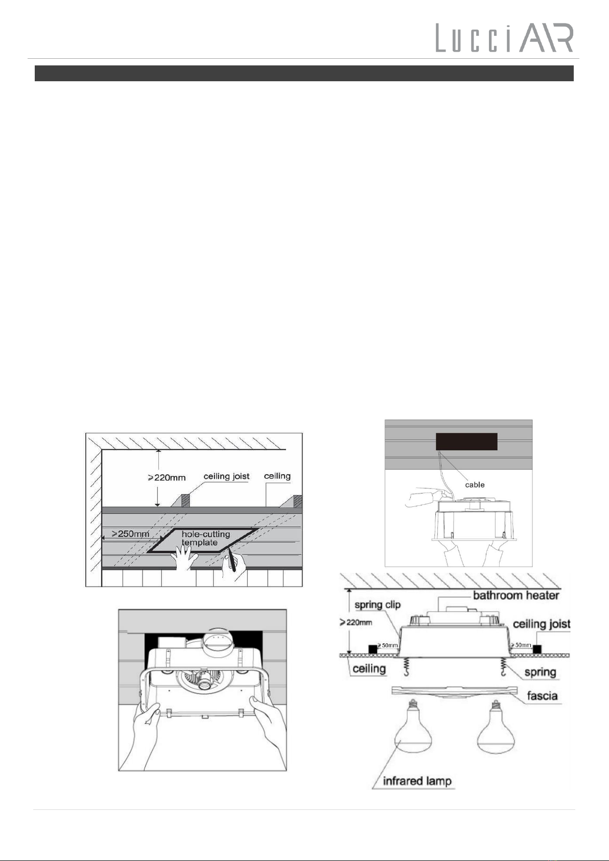
–The unit can be installed in flat ceilings with a minimum height of 2 metres. At least 220mm height clearance
in the ceiling cavity is required to ensure sufficient ventilation for moisture to disperse. The unit must also be
installed at least 250mm away from the walls.
–This product has an insulating ceiling type do-not-cover rating. This product can be used where normally
flammable materials, including building insulation, are or may be present, but cannot be abutted against any
material and cannot be covered in normal use. (Please refer to the Clearance Information section (page 3)
and the do-not-cover rating section (page 4) in this instruction manual for further details.)
–If loose fill insulation or thermal insulation is not fixed into position or if there are loose combustible materials
(e.g. leaves or combustible materials stored in the roof space), a barrier or guard is required as per the
Clearance Information section in this instruction manual.
–Ensure adequate inlets exist through windows, vents or under the door for air flow.
•This appliance is not intended for use by persons (including children) with reduced physical, sensory or mental
capabilities, or lack of experience and knowledge, unless they have been given supervision or instruction
concerning use of the appliance by a person responsible for their safety.
•Children should be supervised to ensure that they do not play with the appliance.
•Lay out all the components on a smooth surface and make sure there are no components missing before
assembling. If parts are missing, return the complete product to the place of purchase for inspection or replacement.
•Check whether the product has been damaged during transport. Do not operate/install any product which appears
damaged in any way. Return the complete product to the place of purchase for inspection, repair or replacement.

Installation Instructions
2 | P a g e v 2 . 0 ( 1 1 / 2 0 2 3 )
Installation Directions
WARNING: Ensure power to the circuit you are working on has been switched OFF before commencing
any electrical work.
1. Remove the heat globes and LED lamp from the lamp holders.
2. Remove the fascia from the body by loosening the spring hooks from the holes of the fascia.
3. The unit may be mounted either between joists using the in-built clip fasteners.
Use this card in its open state as a template. Place in the required location and mark the cut-out hole. Please
refer to the specifications table (Page 4) for the cut-out size.
NOTE: Before cutting, ensure that the area behind the intended location is clear of all cables, pipes and
joists. Ensure all the clearance values (see page 3 & 4) are maintained during and after installation of the
product, thermal insulation, loose fill insulation, loose combustible materials and any structural members.
Once clear, cut out the section along the previously marked lines. (Fig. A).
4. Connect the mains supply wire to the product. See the wiring section (Page 3) for more information. (Fig. B)
5. Install the duct cover on the wall; make sure the blind shutters facing down.
6. Install the vent duct to exhaust hole on the fan body and fix it by a tie cable.
7. Install the other end of vent duct to duct cover and fix it by a tie cable.
8. Insert the unit into the cut-out hole, ensuring to pull the side springs inward so that the body can pass through the
hole without damaging the plaster. Use the four clips to fix to the housing. Ensure that the unit is held securely in
place by the clips. (Fig. C)
9. Hold the fascia against the body of the unit and attach the spring clips to hold the fascia in place. (Fig. D).
10. Install the heat globes and LED lamp into the lamp holders. The globes should be screwed up firmly to ensure a
good electrical contact but don’t over tighten. Next fit the small centre globe in the same way ensuring that it is
positioned centrally. (Fig. D & E & F).
Fig. A
Fig. B
Fig. C
Fig. D

Installation Instructions
3 | P a g e v 2 . 0 ( 1 1 / 2 0 2 3 )
Wiring
NOTE: An isolation switch must be included in the wiring installation. A circuit breaker can be classified as an
isolation switch. The isolation switch allows disconnecting of the product and loads from the mains
240V AC power during maintenance and cleaning of the connected product and connected loads.
•Remove the terminal cover on the fan body by loosening the screws and wire according to the label adjacent to the
terminal block. Make sure all cables are securely connected and reinstall the terminal cover.
•Connect the wiring to the switches as shown in the below electrical diagram.
•Install the plate of wall switch on the wall.
NOTE: This is a Class I product, and must be earthed during wiring and installation.
Clearance Information –AS/NZS 3000 Wiring Rules - Figure 4.9
NOTE: If loose fill insulation or thermal insulation is not fixed into position or if there are loose combustible
materials (e.g. leaves or combustible materials stored in the roof space), a barrier or guard is required.
LOCATION
DISTANCE
DESCRIPTION
HCB
15mm
(Minimum)
Clearance between the top of the product and any structural members, building
elements or objects above it.
Fig. E
Fig. F

Installation Instructions
4 | P a g e v 2 . 0 ( 1 1 / 2 0 2 3 )
Do-not-cover Rating – AS/NZS 60598.2.2 : 2016
This product can be used where normally flammable materials, including building insulation,
are or may be present, but cannot be abutted against any material and cannot be covered in
normal use.
Safety Tips
NOTE: Always ensure the power is switched OFF from the isolation switch/mains before
performing any maintenance cleaning or making any adjustment to the product.
•The supplied LED lamp is NOT dimmable. DO NOT connect the LED lamp with dimming circuits.
•To avoid injury or damage to the luminaire, ensure that power leads and screws are secure before connecting
the power.
•To clean, wipe with a soft damp cloth. Do NOT soak or immerse the luminaire in water or other liquids.
•Ensure that the luminaire does not come in contact with corrosive chemicals/solvents or abrasive cleaners etc
Specifications
SKU #
209121
Colour
White
Rated Voltage
230-240V~ 50Hz
Total Rated Power
1143W
Exhaust Fan - Rated Wattage
35W
Heat Globe - Rated Wattage
1100W Max. (4x Max. 275W)
ES, R125, (Reflector type globe included)
LED lamp - Rated Wattage
8W Max.
ES, R63 (Cool White 4000K LED globe included)
Cut Out Size
320mm x 320mm
Exhaust Fan Duct Diameter
Ø 125mm
IP Rating
IPX4
Luminaire Rating
Do-not-cover
Dimensions
H:275mm W:420mm L:370mm
Weight
3.98kg
SCB
50mm
(Minimum)
Clearance between the side of the product and any structural members, building
elements or objects.
SCI
50mm
(Minimum)
Insulation cannot be abutted against the side of the product and cannot be covered in
normal use.
RISK OF FIRE – BUILDING INSULATION MUST NOT COVER THIS LUMINAIRE
HCB = 15 mm SCB = 50 mm SCI = 50 mm

Installation Instructions
5 | P a g e v 2 . 0 ( 1 1 / 2 0 2 3 )
BATHROOM HEATER WARRANTY CARD
Every Lucci Air Cali 3 in 1 Bathroom Heater, Exhaust Fan & Light is thoroughly inspected and tested before being released for sale. In addition to
any warranties or conditions implied by applicable Statue or Regulation, Lucci Design warrants all of it’s bathroom heaters against defective
workmanship and faulty materials for thirty six (36) months from the original date of purchase. Lucci Design undertakes, at it’s option, to repair or
replace, free of charge, each product or part thereof subject to the below warranty conditions;
1) The fan or relevant part has not been modified, subjected to misuse, neglect, or been involved in an accident.
2) The repairs are not required as a result of normal wear and tear.
3) The product was installed by a licenced electrical contractor in accordance with this instruction manual.
4) No solid state speed control device has been used with the appliance.
5) A copy of the original receipt of purchase is presented.
6) Globes supplied are not covered by this warranty
Lucci Design cannot be held responsible for any repair other than those carried out by it or one of it’s Authorised Service Agents. Please
keep this warranty card in a safe place. This card must be produced in the event of service being required.
IN THE EVENT OF SERVICE BEING REQUIRED, PLEASE CALL
THE LUCCI FAN WARRANTY HOTLINE ON 1800 602 243 BETWEEN
9AM & 5PM (E.S.T) MONDAY TO FRIDAY ENSURING THAT YOU
HAVE THE FOLLOWING DETAILS ON HAND:
MODEL (SKU) NUMBER: __________________________________________________________
DATE OF PURCHASE: ____________________________________________________________
RETAILER: _____________________________________________________________________
RECEIPT NUMBER: ______________________________________________________________
INSTALLED BY: _________________________________________________________________
LICENCE # : ______________________________ PH: __________________________________
DESCRIPTION OF FAULT: _________________________________________________________
______________________________________________________
Table of contents
Popular Heater manuals by other brands

ELMEKO
ELMEKO ML 150 Installation and operating manual

Ecopower Heating
Ecopower Heating VANTAGE NEHV06 Installation and user manual

EOS
EOS 43.FN Assembly and operating instruction

Yoer
Yoer INFERNO OFR1025 manual

Vectra Fitness
Vectra Fitness FM-3510-L/Y user manual

S&P
S&P EMIBLUE - DP Installation manual and instructions for use

uniwatt
uniwatt UGH4002 user guide

Charnwood
Charnwood SLX20 Operating and installation instructions

EQUATION
EQUATION NF05B Assembly manual

Dru
Dru STYLE 3-01 Instructions for installation and operation

Thermoscreens
Thermoscreens CS 1000 Installation, operation and maintenance instructions

CMT
CMT L Series Use, Installation and Maintenance Manual