LUCLAR MANITOBA ENSILER 2400 User guide

USO E MANUTENZIONE
USE AND MAINTENANCE
USO Y MANUTENCION
MODE D’EMPLOI ET ENTRETIEN

DICHIARAZIONE CE DECLARATION CE
EG-ERKLÄRUNG CE DECLARATION
PRODUTTORE CONSTRUCTEUR
HERSTELLER MANUFACTURER
LUCLAR INTERNATIONAL S.r.l.
Via Corvione, 20 - 25010 Isorella - (Brescia) Italy
DESCRIZIONE DELLE MACCHINE PRODOTTE
Macchina per l’insilamento tubolare MANITOBA
NORMATIVE DI RIFERIMENTO AI FINI DELLA SICUREZZA
LE MACCHINE SONO CONFORMI AI REQUISITI DI SICUREZZA STABILITI DALLA DIRETTIVA 89/392/CEE COME MODIFICATA
DALLE DIRETTIVE 91/368/CEE, 93/44/CEE E 93/68/CEE
DESCRIPTION OF MACHINES PRODUCED
MACHINE FOR THE TUBOLAR ENSILAGING MANITOBA
SAFETY REGULATIONS
THE MACHINES COMPLY WITH THE REQUISITES OF DIRECTIVE 89/392/EEC AS MODIFIED WITH DIRECTIVES 91/368/EEC,
93/44/EEC AND 93/68/EEC
BESCHREIBUNG DER HERGESTELLTEN MASCHINEN
MASCHINE FÜR SCHLAUCHEINLAGERN MANITOBA
SICHERHEITSNORMEN
DIE MASCHINEN ENTSPRECHEN DEN VON DER RICHTLINIE 98/37/EWG FESTGESETZTEN SICHERHEITSANFORDERUNGEN
ALS MIT RICHTLINIEN 91/368/EWG, 93/44/EWG UND 93/68/EWG GEÄNDERT
MODELLI MODELLE MODELES MODELS
¾MANITOBA ENSILER 2400
¾------------------------
¾MANITOBA ENSILER 2700
¾------------------------
¾MANITOBA ENSILER 3000
¾------------------------
I

TIMBRO E FIRMA DELL’IMPORTATORE
STEMPEL UND UNTERSCHRIFT DES IMPORTEURS
CACHET ET SIGNATURE DE L’IMPORTATEUR
STAMP AND SIGNATURE OF IMPORTER
SELLO Y FIRMA DEL IMPORTADOR
HANDTEKENING EN STEMPEL VAN DE IMPORTEUR
CANIMBO E ASSINATURA DO IMPORTADOR
6)5$*,'$ .$, 832*5$)+ 72Ȋ(,6$*:*($
TIMBRO E FIRMA DEL VENDITORE
STEMPEL UND UNTERSCHRIFT DES HÄNDLERS
CACHET ET SIGNATURE DU VENDEUR
STAMP AND SIGNATURE OF SELLER
SELLO Y FIRMA DEL VENDEDOR
HANDTEKENING EN STEMPEL VAN DE VERKOPER
CANIMBO E ASSINATURA DO FORNECEDOR
6)5$*,'$ .$, 832*5$)+ 72Ȋ3:/+7+
ELENCO DEI RIPARATORI PIU’ VICINI AL LUOGO DI UTILIZZO DELLA MACCHINA
LISTE DER MECHANIKER, DIE IN DER NÄHE DES EINSATZORTES DER MASCHINE ZU FINDEN SIND
LISTE DES REPARATEURS LES PLUS PROCHES DE L’ENDROIT D’UTILISATION DE LA MACHINE
LIST OF EXPERT REPAIR MEN CLOSEST TO PLACE OF USE
LISTA DE LOS TECNICOS REPARADORES MAS CERCANOS DEL LUGAR EN QUE SE USA LA MAQUINA
LIJST VAN REPARATEURS IN DE DIRECTE OMGEVING VAN DE PLAATS VAN GEBRUIK VAN DE MACHINE
LISTA DOS TÉCNICOS MAIS PRÓXIMOS DO LOCAL DE UTILIZAÇÃO DA MÁQUINA
.$7$/2*26 7:1 3/+6,(67(5:1 681(5*(,:1 Ȉ7+ȃ3(5I2&Ǿ2328 &5+6,0232,(,7$, 72 0+&$1+0$
...............................................................................................................................................................................................
...............................................................................................................................................................................................
...............................................................................................................................................................................................
...............................................................................................................................................................................................
...............................................................................................................................................................................................
II

LEVE DI COMANDO STEUERHEBEL LEVIERS DE COMMANDE CONTROLS
PALANCAS DE MANDO BEDIENINGSHENDELS ALAVANCAS DE COMANDO ȃȆȌȂȆȀ ǽȂǽĬȌȆȋ
Comando espulsore
Die knĦppelsteuerung auswerfer
Lerver motion of expeller
Comando avvolgimento cavo
Die knĦppelsteuerung der kabelauwicklung
Lever motion of the cable winding
Comando rotazione ruote posteriori / anteriori
Die knĦppelsteuerung der hinterräder / vorderräder
Lever motion of the cable winding
Comando posizionamento tappetino
Die knĦppelsteuerung der stellung des förderteppichs
Lever motion of the positioning of the conveyor belt feeder
Comando sollevamento tappetino
Die knĦppelsteuerung der anheben des förderteppichs
Lever motion of the raising of the conveyor belt feeder
Comando movimentazione catena tappetino
Die knĦppelsteuerung der betätigung der förderteppichs
Lever motion of the control of the conveyor bekt feeder chain
PITTOGRAMMI DI SICUREZZA SICHERHEITSSYMBOLE PICTOGRAMMES DE SECURITE SAFETY WARNING SYMBOLS
CARTELES INDICADORES DE SEGURIDAD VEILIGHEIDSPICTOGRAMMEN PICTOGRAMAS DE SEGURANÇA
ȇȀȁȊȆĬȈǺĮȀǽȉ ǺȉĮǺȂǽȀǺȉ
III

Attenzione; leggere le istruzioni per l’uso!
Collocato nella zona frontale, visibile dalla postazione di comando.
Achtung; die Gebrauchsanleitung lesen !
Angebracht im Frontalbereich, ersichtlich von der Steuerstelle aus.
Attention: lire le mode d'emploi!
Placé dans la zone avant, visible du poste de commande.
Important; read the instructions for use!
Placed on the front, visible from the control post.
¡Atención! Leer atentamente el modo de empleo
Situado en la zona delantera, visible desde el puesto de mando.
Let op; lees eerst de gebruiksaanwijzing!
Op de voorkant aangebracht en zichtbaar vanaf de bestuurderspositie.
Atenção; ler as instruções de utilização!
Colocado na zona frontal, visível do posto de comando.
ȇȢȡIJȡȥȓ.ǼțįȖȑIJijı ijțȣ ȡİșȗȔıȣ ȥȢȓIJșȣ!
ȉȠʌȠșİIJȘµȑȞȘ ıIJȘȞ µʌȡȠıIJȚȞȒ ȗȫȞȘ,ȠȡĮIJȒ Įʌȩ IJȘ șȑıȘ İȜȑȖȤȠȣ.
Attenzione alle linee elettriche aeree!
Collocato nella zona frontale, visibile dalla postazione di comando.
Vorsicht bei elektrischen Freileitungen!
Angebracht im Frontalbereich, ersichtlich von der Steuerstelle aus.
Attention aux lignes électriques aériennes!
Placé dans la zone avant, visible du poste de commande.
Watch for overhead electric wires!
Placed on the front, visible from the control post.
¡Atención a las líneas eléctricas aéreas!
Situado en la zona delantera, visible desde el puesto de mando.
Let op: bovengrondse sterkstroomleidingen!
Op de voorkant aangebracht en zichtbaar vanaf de bestuurderspositie.
Atenção às linhas eléctricas aéreas!
Colocado na zona frontal, visível do posto de comando.
ȇȢȡIJȡȥȓ IJijțȣ ıȟįȒȢțıȣ șȝıȜijȢțȜȒȣ ȗȢįµµȒȣ!
ȉȠʌȠșİIJȘµȑȞȘ ıIJȘȞ µʌȡȠıIJȚȞȒ ȗȫȞȘ,ȠȡĮIJȒ Įʌȩ IJȘ șȑıȘ İȜȑȖȤȠȣ.
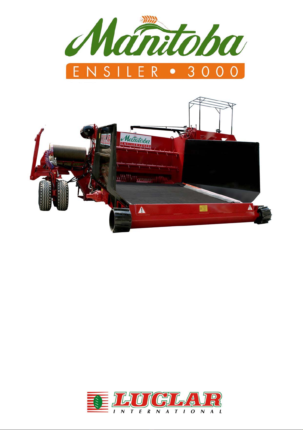
Attenzione. Non sostare nella zona tra il trattore ed il carro!
Collocato nella zona frontale, visibile dalla postazione di comando.
Achtung. Sich nicht zwischen dem Traktor und dem Wagen aufhalten !
Angebracht im Frontalbereich, ersichtlich von der Steuerstelle aus.
Attention: Ne pas stationner dans la zone entre le tracteur et la remorque!
Placé dans la zone avant, visible du poste de commande.
Caution. Do not stand between the tractor and the cart!
Placed on the front, visible from the control post.
¡Atención! No detenerse en la zona entre el tractor y el carro.
Situado en la zona delantera, visible desde el puesto de mando.
Let op: niet in het gebied tussen de tractor en de wagen blijven staan!
Op de voorkant aangebracht en zichtbaar vanaf de bestuurderspositie.
Atenção. Não permanecer na zona entre o tractor e o carro!
IV

Attenzione alle mani – coclee in rotazione!
Collocato sul posteriore della macchina.
Auf die Hände achtgeben – Schnecken in Bewegung!
Angebracht auf der Maschinenrückseite.
Angeb Attention aux mains – Vis en rotation!
Placé à l'arrière de la machine.racht auf der Maschinenrückseite
Watch your hands – screws in motion!
Placed on the back of the machine.
Atención a las manos – ¡Roscas en rotación!
Situado en la parte trasera del equipo.
Let op voor uw handen – roterende schroeven!
Aangebracht op de achterkant van de machine.
Atenção às mãos – cócleas em rotação!
Colocado na parte posterior da máquina.
ȇȢȡIJȡȥȓ IJijį ȥȒȢțį - ȜȡȥȝȔıȣ IJı ʍıȢțIJijȢȡĴȓ!
ȉȠʌȠșİIJȘµȑȞȘ ıIJȠ ʌȓıȦ µȑȡȠȢ IJȠȣ µȘȤĮȞȒµĮIJȠȢ.
Attenzione!
Parti in movimento, allontanare le persone dalla zona pericolosa.
Achtung!
Bewegliche Teile, Personen aus dem Gefahrenbereich verweisen.
Attention!
Pièces en mouvement, éloigner toute personne de la zone dangereuse.
Caution!
Parts in motion, keep people away from danger zone.
¡Atención!
Elementos en movimiento, alejar a todas las personas de la zona peligrosa.
Let op!
Bewegende delen, verwijder alle personen uit het gevaarlijke gebied.
Atenção!
Partes em movimento, afastar as pessoas da zona perigosa.
ȇȢȡIJȡȥȓ!
ȂȑȡȘ İȞ țȚȞȒıİȚ,ĮʌȠµĮțȡȪȞİIJİ IJȠȣȢ ĮȞșȡȫʌȠȣȢ Įʌȩ IJȘȞ İʌȚțȓȞįȣȞȘ ȗȫȞȘ.
Divieto di stazionamento nell’area di lavoro della macchina.
Collocato sul carter fresa e presso il nastro di scarico.
Verbot, sich im Arbeitsbereich der Maschine aufzuhalten.
Angebracht auf dem Gehäuse der Fräsmaschine und beim Auslaßband
Défense de stationnement dans la zone de travail de la machine.
Placé sur le carter de la fraise et près de la bande de déchargement.
Prohibition to stand in the machine operating zone.
Placed on the mill casing and near the discharge belt.
Prohibido detenerse en el área de trabajo de la máquina.
Situado sobre la cubierta de protección de la fresa y a proximidad de la cinta de
descarga.
Verboden binnen het werkgebied van de machine te verblijven.
Aangebracht op de carter van de frees en bij de afvoerband.
É proibido estacionar na área de trabalho da máquina.
Colocado no cárter da fresa e
p
róximo do ta
p
ete de descar
g
a.
Indicazione di PERICOLO.
Collocata presso il nastro di scarico e su tutti i ripari.
GEFAHRENHINWEIS .
Angebracht beim Auslaßband und auf allen Schutzvorrichtungen.
Indication de DANGER.
Placé près de la bande de déchargement et sur tous les protecteurs.
DANGER sign.
Placed near the discharge belt and on all guards.
Indicación de PELIGRO.
Situado cerca de la cinta de descarga y en todas las cubiertas de protección.
GEVAARAANDUIDING
Aangebracht bij de afvoerband en op alle afschermingen.
Indicação de PERIGO.
Colocado próximo do tapete de descarga e em todas as protecções.
dzȟİıțȠș ȁȀȄǼȋȄȆȋ.
ȉȠʌȠșİIJȘµȑȞȘ ıIJȘȞ IJĮȚȞȓĮ İțijȩȡIJȦıȘȢ țĮȚ ı'ȩȜĮ IJĮ țĮȜȪµµĮIJĮ.
V

Segnalazione punti di INGRASSAGGIO.
Hinweis für die SCHMIERSTELLEN.
Signalisation des points de GRAISSAGE.
GREASE POINT marker.
Señalización de los puntos de ENGRASE.
Signalering SMEERPUNTEN.
Assinalação dos pontos de LUBRIFICAÇÃO.
ǽʍțIJȓµįȟIJș IJșµıȔȧȟ ĬȈǺȉǺȈȀȉȃǺȊȆȉ.
Segnalazione punti di aggancio per sollevamento con gru.
Hinweis für die Einhakstellen zum Anheben mit Kran.
Signalisation des points d'attelage pour levage avec grue.
Hoisting point mark for hoisting with crane.
Señalización de los puntos de enganche para el levantamiento con grúa.
Signalering van de hijspunten voor het optillen met een hijskraan.
Assinalação dos pontos de enganche para elevação com grua.
ǽʍțIJȓµįȟIJș IJșµıȔȧȟ įȗȜȔIJijȢȧIJșȣ ȗțį įȟȫȦȧIJș µıȗıȢįȟȪ.
Indicazione velocità massima di traino consentita.
Angabe bezüglich der maximal zugelassenen Zuggeschwindigkeit.
Indication de la vitesse maximum de remorquage autorisée.
Maximum speed with load.
Indicación de la velocidad máxima de remolque autorizada.
Aanduiding voor de maximaal toegestane snelheid met aanhanger.
Indicação da velocidade máxima de reboque consentida.
dzȟİıțȠș µȒȗțIJijșȣ ıʍțijȢıʍijȓȣ ijįȥȫijșijįȣ ȒȝȠșȣ.
Segnalazione di parti sporgenti della macchina.
Hinweis auf hervorragende Maschinenteile
Signalisation d'éléments en saillie de l'équipement.
Indication of protruding parts.
Señalización de partes fuera de gálibo del equipo.
Signalering voor uitstekende delen van de machine.
Assinalação de partes salientes da máquina.
ǽʍțIJȓµįȟIJș ʍȢȡıȠıȥȪȟijȧȟ µıȢȬȟ ijȡȤ µșȥįȟȓµįijȡȣ.
Indicazione pressione massima circuito idraulico.
Collocato presso il blocco comandi.
Angabe bezüglich des maximalen hydraulischen Drucks
Angebracht bei der Steuerungseinheit
Indication de la pression maximum du circuit hydraulique.
Placé à côté du bloc de commandes.
Indication of maximum pressure in hydraulic circuit.
Placed near control panel.
Indicación de la presión máxima del circuito hidráulico.
Situado cerca del bloque de mandos.
Aanduiding voor de maximumdruk van het hydraulische circuit.
Aangebracht bij de besturingsorganen.
Indicação da pressão máxima do circuito hidráulico.
Colocado próximo do bloco de comandos.
dzȟİıțȠș µȒȗțIJijșȣ ʍȔıIJșȣ ȤİȢįȤȝțȜȡȫ ȜȤȜȝȬµįijȡȣ.
ȉȠʌȠșİIJȘµȑȞȘ ıIJȠ ʌȜĮȓıȚȠ İȞIJȠȜȫȞ.
VI

Numero massimo di giri presa di forza trattore e senso di rotazione.
Collocato sul timone della macchina.
Maximale Anzahl der Antriebsdrehungen des Traktors und Drehrichtung.
Angebracht an der Maschinendeichsel
Régime maximum de la prise de force du tracteur et sens de rotation.
Placé sur le timon de l'équipement.
Maximum rpm of power takeoff on tractor and direction of rotation. Placed
on machine rudder.
Número máximo de revoluciones de la toma de fuerza del tractor y
sentido de rotación. Situado sobre la vara del equipo.
Maximum aantal toeren van de aftak-as van de traktor en draairichting.
Aangebracht op het stuurhendel van de machine.
Número máximo de rotações por minuto da tomada de força do tractor e
sentido de rotação. Colocado na cauda da máquina.
ȃȒȗțIJijȡȣ įȢțȚµȪȣ IJijȢȡĴȬȟ ȝȓȦșȣ ıȟȒȢȗıțįȣ ijȢįȜijȒȢ Ȝįț ĴȡȢȑ ʍıȢțIJijȢȡĴȓȣ.
ȉȠʌȠșİIJȘµȑȞȘ ıIJȠ IJȚµȩȞȚ IJȠȣ µȘȤĮȞȒµĮIJȠȢ.
Indicazione pressione di gonfiaggio pneumatici.
Angabe zum maximalen Reifendruck.
Indication de la pression de gonflage des pneumatiques.
Indication of tire inflation pressure.
Indicación de la presión de inflado de los neumáticos.
Aanduiding van de bandenspanning.
Indicação da pressão de enchimento dos pneumáticos.
dzȟİıțȠș ʍȔıIJșȣ įȒȢį ʍȟıȤµįijțȜȬȟ.
VII

CONTENTS
GENERAL RULES AND INSTRUCTIONS............................................................................................................1
MANUFACTURER’S LIABILITY LIMITS .................................................................................................. 1
REFERENCE STANDARDS .................................................................................................................... 1
CONSERVATION OF MANUAL AND CERTIFICATION ......................................................................... 1
DEFINITIONS........................................................................................................................................... 1
IDENTIFICATION OF THE MACHINE ..................................................................................................... 2
OBLIGATIONS AND RESPONSIBILITIES .............................................................................................. 3
DESCRIPTION OF THE MACHINES.....................................................................................................................3
TECHNICAL FEATURES ......................................................................................................................................3
CONDITIONS AND RESTRICTIONS ON USE .....................................................................................................4
SAFETY..................................................................................................................................................................4
GENERAL INSTRUCTIONS .................................................................................................................... 4
SAFETY GUARDS AND DEVICES INSTALLED ON THEMACHINE...................................................... 6
SAFETY SIGNALS ................................................................................................................................... 7
CONTROLS............................................................................................................................................................7
USE OF THE MACHINE ........................................................................................................................................8
RECOMMENDATIONS FOR USE OF THE MACHINE ........................................................................... 8
CONNECTION TO THE TRACTOR......................................................................................................... 8
TOWING................................................................................................................................................... 8
STARTING................................................................................................................................................ 9
USE OF THE MACHINE ....................................................................................................................... 12
JAMMING/OBSTRUCTION.................................................................................................................... 14
TRANSPORT .......................................................................................................................................................15
MAINTENANCE/REPAIRS..................................................................................................................................15
GENERAL INSTRUCTION .................................................................................................................... 15
MAINTENANCE RECOMMENDATIONS .............................................................................................. 15
OPERATIONS AND FREQUENCY .......................................................................................................16
TABLE OF SUGGESTED OILS AND LUBRICANTS ............................................................................ 23
TROUBLESHOOTING .........................................................................................................................................23
ACCESSORIES....................................................................................................................................................24
STANDARD ACCESSORIES SUPPLIED WITH THE MACHINE ......................................................... 24
OPTIONAL ACCESSORIES ................................................................................................................. 24
WARRANTY ……………………………………………………………………………………………………………...24
1

GENERAL RULES AND INSTRUCTIONS
This symbol is a “CAUTION” warning and draws attention to important safety messages.
When you find this symbol, read the message carefully to avoid the risk of serious injury
to yourself or others.
Improper use of the machine or failure to apply the safety regulations can cause serious
injury, even death.
Before starting the machine:
1. Read this manual carefully.
2. Make sure there are no persons within the radius of action of the machine.
3. Be sure you know and apply the safety regulations in effect.
THE INFORMATION AND ILLUSTRATIONS IN THIS PUBLICATION ARE NOT BINDING ON LUCLAR
INTERNATIONAL SRL; THE COMPANY RESERVES THE RIGHT TO AMEND THIS MANUAL WITHOUT
NOTICE WHEN MODIFICATION OF THE PRODUCTION IS DEEMED NECESSARY TO IMPROVE IT.
MANUFACTURER’S LIABILITY LIMITS
Failure to observe the precautions or specific instructions provided in this manual, improper use of the
equipment, wholly or in part, use of unauthorized spare parts and use of the machine by persons without the
necessary qualifications violate all safety regulations concerning design, construction and proper use of the
equipment and relieve Luclar International S.r.l. of any liability in the event of injury or damage to persons or
property.
Luclar International S.r.l. is not liable in case of failure of the user to observe the safety precautions
indicated in this manual.
REFERENCE STANDARDS
In drawing up this manual, the indications provided in the following documents were used:
xEnclosure “I” to EEC Directive 98/EEC: point 1.7.4;
xUNI EN 292/2 - 1992, point 5.5.
xUNI EN 703 - 1997, point 5.1
xUNI EN 982 - 1997, point 7
CONSERVATION OF MANUAL AND CERTIFICATION
This document is an integral part of the machine. It must be kept in a safe place and used throughout the entire
operating life of the machine, even in the event of transfer of the equipment to third parties.
The “Certificate of conformity” issued by the manufacturer must also be conserved.
DEFINITIONS
Pursuant to the EEC 89/392 “Machinery Directive” and subsequent amendments, the following definitions are
provided.
Dangerous areas: any area in and/or near a machine where the presence of an exposed person
constitutes a risk for the safety and health of that person;
Exposed person: any person partially or fully inside a dangerous area;
Operator: the person(s) with the task of operating, adjusting, carrying out ordinary maintenance or
cleaning of the machine.
User: the organization or persons responsible for and/or owners of the machine.
2

IDENTIFICATION OF THE MACHINE
IDENTIFICATION PLATE
For ordering spare parts, requesting information or service, always indicate to your distributor the type and
serial number of your Luclar machine. You will find these information on the identification plate located on the
platform.
TERMINOLOGY USED TO INDICATE MACHINE SIDES
“Right”, “Left”, “Front”, and “Rear” used in this manual, indicate the machine sides, seen from the control
position.
1. Front side
2. Left side
3. Right side
4. Rear side
4
2 3
1
3

OBLIGATIONS AND RESPONSIBILITIES
RESPONSIBILITIES OF THE EMPLOYER
The employer is responsible for disclosure of this document to all the personnel assigned to operate the
machine.
OBLIGATIONS IN THE EVENT OF MEASURES CARRIED OUT ON MACHINES
All persons using or working on the machine in any way should prepare adequately, by consulting the manual
before any action is taken.
OBLIGATION TO OBSERVE REGULATIONS
The operators, in addition to diligently following the instructions in this document, must also apply
and respect any pertinent general accident prevention regulations of EC directives and the legislation of
the country where the machine is used.
OBLIGATIONS IN THE EVENT OF MALFUNCTIONS AND /OR POTENTIAL HAZARDS
The operators should to report any defects and/or potentially hazardous situations, which may arise to their
direct supervisors or managers.
OBLIGATIONS OF THE USER
The user and/or third parties (excluding employees of Luclar International S.r.l. or authorized repair personnel)
are strictly prohibited from making changes of any type or extent to the machine or its functions, or to this
technical document.
DESCRIPTION OF MACHINES
The information written in this manual is valid for the series MANITOBA ENSILER 2400 and
3000.
The Manitoba Ensiler is composed by no.01 coiler, no.02 augers and no.01 feeding conveyor.
The Manitoba Ensiler allows the complete mechanization of the storage operations of the products in the
animal breeding; the tubular bag is suitable for their optimum conservation.
TECHNICAL FEATURES
Rated rotation frequency of the shaft driven on the
machine by the power take-off 540 rpm
Direction of rotation of the shaft driven on the machine
by the power take-off Counter-clockwise (as seen from the control position)
Admissible pressure of hydraulic circuits 210 bar
Admissible capacity of hydraulic circuits 32 l/min
125 l/min
Max. noise level Lw (A) 106.0 dB(A)
Noise level at control position 87.2 dB(A)
4

CONDITIONS AND RESTRICTIONS ON USE
THE MANITOBA ENSILER CAN BE USED FOR PROCESSING ONLY SUCH MATERIALS AS: GRASS,
HAY, STRAW, CORN, SILAGE AND SIMILAR PRODUCTS.
As the machines are designed and manufactured only for processing the above materials, any other
use is to be considered improper.
In particular it is absolutely forbidden to use the machines for moving and handling materials not specifically
envisaged, such as for example: wood, loose chemical substances, combustible, inflammable and explosive
materials, gravel, metallic material, tyres.
In case of improper use Luclar International is not liability in the event of injury or damage to persons
or property and any type of warranty on the machine is invalidated.
In addition, the following instructions are essential for use:
Max. allowed ground slope: 10% transverse, 10% longitudinal
Avoid working on muddy, sandy or soft ground.
For a good functioning and a correct conservation of the machine axles:
Never exceed the maximum speed of 8 km/hr. (except for the models approved for road traffic)
Avoid bumping into obstacles or holes
Avoid violent shifts of the cargo
Never use on saline or highly corrosive soils
Avoid immersing the axles and/or brakes in fluids.
SAFETY
GENERAL INSTRUCTIONS
BEFORE USING THE MACHINE
¾Do not use the machine until the instructions, recommendations, usage restrictions
and warnings contained in this manual have been read and fully understood.
¾The presence of mud, oil, ice (in winter) on the footboards and on the access handles
can cause accidents. Make sure that they are always clean.
¾Inspect the machine daily in order to verify that there are no leakages of oil or
hydraulic fluid. Tighten parts as needed and make all necessary replacements.
¾Make sure that all the controls and safety devices are in perfect working order by
checking them in a safe, secure place before starting any work.
¾Check and make a note of any possible risks before towing the machine to a new work
site.
¾Become very familiar with the symbols on the warning signs fastened to the machine.
Make sure that they are always clean and legible.
¾Regularly check the pressure of the tyres.
¾Always check that the cardanic transmission shaft from the power take-off of the
tractor bears the EC stamp and is equipped with protection in good condition.
5

WORKING WITH THE MACHINE
¾The machine must be operated by a single operator only; nobody else should be
allowed near the machine during its use.
¾The machine can be controlled only from the control platform placed on it.
¾It is absolutely forbidden to stand between the tractor and the machine when it is in
operation. Risk of crash.
¾Do not approach the loading area - chain in motion
¾Do not use the machine for transporting persons, animals or property.
¾Do not stand on the loading devices and use them as lifting devices.
¾Do not remove or tamper with the safety devices, guards and casings on the machine.
PARKING THE MACHINE
After use, to park the machine safely, proceed as follows:
1. Move the machine to a flat place on horizontal ground.
2. Immobilize the machine with the lever of the parking brake (if any) or using the chocks.
3. Stop the tractor and remove the ignition key.
4. Disconnect the pto shaft from the tractor and place it on the machine support.
5. Check that all guards supplied with the machine are correctly positioned.
6. Open the hinged edge (danger of conveyor reduction gear break)
7. Close the loading conveyor
MAINTENANCE AND INSPECTION
¾Do not perform any maintenance work until you are sure you understand the
instructions in this manual.
¾Use personal protection gear suitable for the operations to be carried out and
appropriate apparel.
¾In particular, when carrying out operations on the coiler on the milling cutter, it is
compulsory to wear : OVERALLS MADE OF STRONG FABRIC, SAFETY FOOTWEAR
WITH ANKLE PROTECTION, GLOVES.
¾Before carrying out any maintenance, immobilize the machine as indicated for parking.
¾In case of welding operations, connect the mass of the welding device to the element
to be welded. Never put the welding device on an element of the hydraulic circuit.
¾Never weld near a tyre. Remove the tyre before doing any welding in the vicinity.
¾Check the condition of the tyres periodically and always respect the inflation pressure
defined in relation to the tyre type and nature of the terrain.
¾When checking tyre pressure or during inflation never stand in front of the tyres but
always on the tread side.
¾Improper maintenance or adjustment may cause serious danger.
In case of doubt concerning procedures of maintenance or adjustment, contact your
LUCLAR distributor.
¾Unauthorized modifications made to the machine may cause serious danger. Do not
make any modification to the machine without the prior authorization of LUCLAR.
6

WARNING SIGNS
¾Illegible or missing warning signs are a serious hazard. Check them every day.
¾Make sure all signs are perfectly legible, clean them regularly and replace them with
new ones, if they are damaged, missing or painted over.
In case of replacement of a part on which a sign is attached, apply a new one to the
replaced part.
SAFETY GUARDS AND DEVICES INSTALLED ON THE MACHINE
FIXED GUARDS
The machine is equipped with several fixed guards, to assure an adequate safety level.
The most important are the following.
CE guard on the pto shaft joint.
Protection guard
for the pro shaft
joint
Conveyor
chain casing
Platform
protection
casing
Protection
casing
7

SAFETY VALVES
The hydraulic circuit is equipped with safety valves at the following points:
Hydraulic jacks for lowering of conveyor
The automatic stop valve directly installed on the hydraulic jack prevents the lowering of the conveyor in
case of rupture/breakdown of the hydraulic circuit, until the correct working pressure has been restored.
hydraulic jacks stop valve loading
conveyor lowering
SAFETY SIGNALS
Adhesive signs are applied to the machine to inform the operator
of residual risks connected with the use of the machine;
of correct use procedures;
of the location of parts needing service.
CONTROLS
The machine control actuators consist of levers.
The controls are of “spring return “ type (must be held in position), except for:
The control to start the discharge conveyor motor
Pictogram labels at the base of each lever indicate the functions of each lever.
You will find the explanations on page III.
8

USE OF THE MACHINE
RECOMMENDATIONS FOR USE OF THE MACHINE
¾Make sure that all organs of the machine and devices function regularly during use.
Bear in mind that most of the problems and damages that may arise during use of the machine are caused
by loosening of fasteners.
Since in the first stage of machine life there is a general settling of mechanical parts and hydraulic
connections, it is ESSENTIAL to check the machine with utmost care.
¾All casings must be mounted during use of the machine.
¾The machine is not approved for road traffic.
CONNECTION TO THE TRACTOR
1. Connect the hitch bar eyelet to the tractor by means of a steel bolt with a minimum diameter of 35 mm,
equipped with a transverse safety plug.
2. Clean and grease the tractor PTO and machine shaft, before installing the pto shaft transmission. Make
sure that the pto shaft is equipped with EC stamp and declaration in conformity with the 89/392/EC
directive. The machine is equipped with special support to hold up the pto shaft during inactivity.
3. Check the hydraulic oil level and the transmission oil level (see maintenance instructions).
4. If the machine is equipped with manual mechanic brake installation, connect it to the respective tractor
circuit by means of the kit supplied with the machine.
5. If the machine is equipped with manual mechanic brake installation, install the control lever near the tractor-
driving seat by means of the kit supplied with the machine.
6. Check the fastening of the feeding conveyor and of the back stop.
TOWING
DO NOT MAKE SHARP BENDS, THE HITCH BAR COULD BREAK
Before towing the machine, make sure to have
removed the pins for the steering block.
Steering
block pins
9

STARTING
Before loading the machine, start the power take-off and give it a 2/3-minute warm-up period to heat
the hydraulic oil to the proper temperature for use. In the winter season or in cold climates the warm up
period must be 4 or 5 minutes.
After positioning the machine in the place of use and before starting to work, make sure
that no persons or animals are located in the range of action.
Before using the machine make sure the respect of the “conditions and limitations of use”.
Check the meaning of the labels attaches by the control levers.
HITCH BAR FASTENING
Take the hitch bar from the special hooks located
on the platform.
Fasten the rear hitch bar in the special location
using the pin delivered with the machine.
Hitch bar
10

WHEELS ROTATION
¾Take out the steel pins which stop the rear and
front wheels rotation and rotate them to the
working direction (the front and rear wheels
must be kept parallel).
Steel pins
BAG MOUNTING
A little crane equipped with manual winch to make easier the mounting of the bag is supplied with the Manitoba
Ensiler.
¾Lower the crane to the ground and hook up the bag with the special support; check that the bag is
mounted in the right way (see picture 1).
¾Bring the bag in the right position, hook off the bag support by means of the special lever, put the bag
in and close everything.
Picture 1
BACK-STOP
Hook off the back-stop and bring it to a distance of about 2 metres; the back-stop is equipped with two little
wheels that facilitate this operation.
Fasten with the special hooks
11

Hooks for the back-stop
BAG CLOSING AND BACK-STOP HOOKING
Take off about 1 metre of bag, twist it sometimes and tie it up well with twine, bend the twisted part and tie up
everything again.
Put back the bag against the back-stop making sure
that the side closed with the twine remains below.
Connect the chains of the back-stop to the hooks of
the braking cable.
CONVEYOR
Unscrew the nut (A) that stop the conveyor safety
chain. Lower the conveyor till the wheels lean against
the ground.
Raise the conveyor sides till they lean against the
walls of the machine.
Check that no persons or animals are in the area of conveyor lowering.
DANGER OF DEATH.
12
This manual suits for next models
2
Table of contents
Popular Farm Equipment manuals by other brands

Farmet
Farmet KULTIS 6 operating manual

coloQuick
coloQuick Pasteur II user manual

Raven
Raven Slingshot Field Hub 2.0 Configuration manual

Galcon
Galcon Fertijet Installation guide and user's manual

MacDon
MacDon FlexDraper FD2 Series manual

CUSTOM PRODUCTS
CUSTOM PRODUCTS CozyCab TORO A-10855 Mounting instructions

patura
patura MaxiBox P250 Mounting instructions

Omlet
Omlet Eglu Cube instructions

horsch
horsch Focus 4 TD operating instructions

AgXcel
AgXcel Synergist GX40 System Reference manual

Chore-Time
Chore-Time ATF Installation and operator's manual

FPM Agromehanika
FPM Agromehanika FPM 619 091 assembly, operation and maintenance guide