Visit: www.abisupport.com Call Toll Free: 877-788-7253Email: support@abiattachments.com
45
Safety
WARNING! The SAFETY ALERT SYMBOL indicates there is a potential hazard to personal safety involved and
extra safety precaution must be taken. When you see this symbol, be alert and carefully read the message
that follows it. In addition to design and configuration of equipment, hazard control, and accident prevention
are dependent upon the awareness, concern, prudence, and proper training of personnel involved in the
operation, transport, maintenance, and storage of equipment.
SAFETY AT ALL TIMES
Careful operation is your best assurance against
an accident. All operators, no matter how much
experience they may have, should carefully read
this manual and other related manuals, or have the
manuals read to them, before operating the tow
vehicle and this implement.
SAFETY PRECAUTIONS FOR CHILDREN
Tragedy can occur if the operator is not alert to the presence of
children. Children generally are attracted to implements and
their work.
SHUTDOWN & STORAGE
WARNING! Cancer and reproductive harm- www.P65Warnings.ca.gov
CALIFORNIA PROPOSITION 65
• Thoroughly read and understand the “Safety
Label” section. Read all instructions noted on
them.
• Do not operate the equipment while under the
influence of drugs or alcohol as they impair
the ability to safely and properly operate the
equipment.
• The operator should be familiar with all functions
of the tow vehicle and attached implement and be
able to handle emergencies quickly.
• Make sure all guards and shields appropriate for
the operation are in place and secured before
operating implement.
• Keep all bystanders away from equipment and
work area.
• Start tow vehicle from the driver’s seat with
hydraulic controls in neutral.
• Operate tow vehicle and controls from the driver’s
seat only.
• Never dismount from a moving tow vehicle or leave
tow vehicle unattended with engine running.
• Do not allow anyone to stand between tow vehicle
and implement while backing up to implement.
• Keep hands, feet, and clothing away from power-
driven parts.
• While transporting and operating equipment,
watch out for objects overhead and along side such
as fences, trees, buildings, wires, etc.
• Do not turn tow vehicle so tight as to cause hitched
implement to ride up on the tow vehicle’s rear
wheel.
• Store implement in an area where children
normally do not play. When needed, secure
attachment against falling with support blocks.
• Never assume children will remain where you last saw
them.
• Keep children out of the work area and under the watchful
eye of a responsible adult.
• Be alert and shut the implement and tractor down if
children enter the work area.
• Never carry children on the tractor or implement. There is
not a safe place for them to ride. They may fall o and be
run over or interfere with the control of the tow vehicle.
• Never allow children to operate the tow vehicle or
implement, even under adult supervision.
• Never allow children to play on the tow vehicle or
implement.
• Use extra caution when backing up. Before the tractor
starts to move, look down and behind to make sure the
area is clear.
If engaged, disengage power take-o.
Park on solid, level ground and lower implement to ground
or onto support blocks.
Put tractor in park or set park brake, turn o engine, and
remove switch key to prevent unauthorized starting.
Relieve all hydraulic pressure to auxiliary hydraulic lines
Wait for all components to stop before leaving operator’s
seat.
Use steps, grab-handles and anti-slip surfaces when
stepping on and o the tractor.
Detach and store implement in an area where children
normally do not play. Secure implement using blocks
and supports.
•
•
•
•
•
•
•
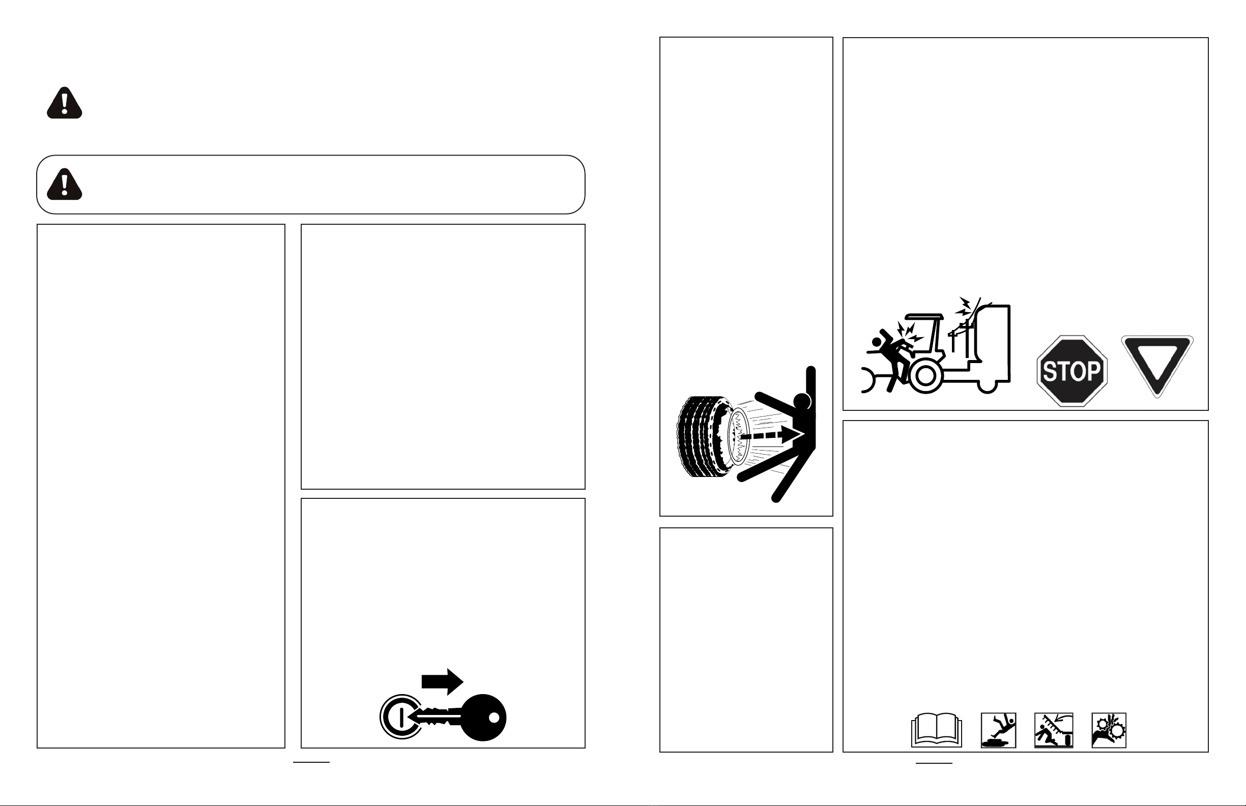
TIRE SAFETY
OPERATION SAFETY
TRANSPORT SAFELY
PRACTICE SAFE MAINTENANCE
• Tire changing can be dangerous
and must be performed by trained
personnel using the correct tools
and equipment.
• Always maintain correct tire
pressure. Do not inflate tires
above recommended pressures
shown in the Operator’s Manual.
• When inflating tires, use a clip-on
chuck and extension hose long
enough to allow you to stand
to one side and NOT in front of
or over the tire assembly. Use a
safety cage if available.
• Securely support the implement
when changing a wheel.
• When removing and installing
wheels, use wheel handling
equipment adequate for the
weight involved.
• Make sure wheel bolts have been
tightened to the specified torque.
• Some attachments may have
foam or sealant inside them and
must be disposed of properly.
• Stay alert for holes, rocks, and
roots in the terrain and other
hidden hazards. Keep away from
drop-os.
• Stop implement immediately
upon striking an obstruction.
Turn engine o, remove key,
inspect and repair any damage
before resuming operation.
• Never operate tractor and
implement under trees with low
hanging limbs. Operators can be
knocked o the tractor and then
run over by implement.
• Comply with federal, state, and
local laws.
• Use towing vehicle and trailer of
adequate size and capacity Secure
equipment towed on a trailer with
tie downs and chains.
• Sudden braking can cause a
towed trailer to swerve and upset.
Reduce speed if towed trailer is
not equipped with brakes.
• Avoid contact with any overhead
utility lines or electrically charged
conductors.
• Always drive with load on end of
loader arms low to the ground.
• Always drive straight up and
down steep inclines with heavy
end of a tow vehicle with loader
attachment on the “uphill” side.
• Understand procedure before doing
work. Refer to the Operator’s Manual
for additional information.
• Work on a level surface in a clean dry
area that is well-lit.
• Lower implement to the ground
and follow all shutdown procedures
before leaving the operator’s seat to
perform maintenance.
• Do not work under any hydraulic
supported equipment. It can settle,
suddenly leak down, or be lowered
accidentally. If it is necessary to
work under the equipment, securely
support it with stands or suitable
blocking beforehand.
• Use properly grounded electrical
outlets and tools.
• Use correct tools and equipment for
the job that are in good condition.
• Allow equipment to cool before
working on it.
• Engage park brake when stopped on
an incline.
• Maximum transport speed for an
attached equipment is 20 mph. DO
NOT EXCEED. Never travel at a speed
which does not allow adequate
control of steering and stopping.
Some rough terrains require a slower
speed.
• As a guideline, use the following
maximum speed weight ratios for
attached equipment:
- 20 mph when weight of attached
equipment is less than or equal
to the weight of machine towing
the equipment.
- 10 mph when weight of attached
equipment exceeds weight of
machine towing equipment but
not more than double the weight.
• IMPORTANT: Do not tow a load that
is more than double the weight of the
vehicle towing the load.
• Disconnect battery ground cable
(-) before servicing or adjusting
electrical systems or before welding
on implement.
• Inspect all parts. Make certain parts
are in good condition & installed
properly.
• Replace parts on this implement
with genuine ABI Attachments parts
only.
• Do not alter this implement in a
way which will adversely aect its
performance.
• Do not grease or oil implement
while it is in operation.
• Remove buildup of grease, oil, or
debris.
• Always make sure any material and
waste products from the repair and
maintenance of the implement are
properly collected and disposed.
• Remove all tools and unused parts
before operation.