Lumel S4AO User manual

1
USERS MANUAL
4 ANALOG OUTPUTS MODULE
S4AO

2

3
Contents
1. APPLICATION ................................................................... 5
2. MODULE SET.................................................................... 6
3. BASIC REQUIREMENTS, OPERATIONAL SAFETY ........................... 7
4. INSTALLATION .................................................................. 8
4.1. Mounting ......................................................................................8
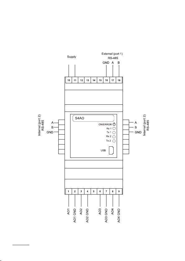
4.2. ExtErnal ConnECtion DiagraMs ...........................................10
4.3. latEral bus................................................................................12
5. OPERATION ................................................................... 13
5.1 Configuration............................................................................13
5.2 slavE opErations ......................................................................13
5.3 MastEr opErations...................................................................14
5.4 CoopEration with othEr DEviCEs (latEral bus)................15
5.5 CountErs .....................................................................................16
5.6 inDiviDual CharaCtEristiC ......................................................18
5.7 short CirCuits ...........................................................................19
5.8 tiMEout ........................................................................................19
5.9 DEviCE Configuration using E-Con prograM......................23
5.9.1 Configuration paraMEtErs ..........................................25
5.9.2 status valuE.....................................................................29
5.9.3 ConfigurED valuEs..........................................................30
6. SERIAL INTERFACES ......................................................... 31
6.1 rs-485intErfaCEs – list of paraMEtErs...............................31
6.2 usb intErfaCE – list of paraMEtErs.....................................32
6.3 Map of s4ao MoDulE rEgistErs..............................................32
7. BEFORE DECLARING A DAMAGE ........................................... 50
8. SOFTWARE UPDATE ......................................................... 51
9. TECHNICAL DATA ............................................................ 53
10. ORDERING CODE ............................................................ 56

4

5
1. APPLICATION
The 4-channels analog outputs module is designed
to convert numerical data to standard (voltage or current) sig-
nals, by means of the MODBUS protocol.
The output signals are divided into 2 sets of 2 outputs, which
are isolated between themselves. RS-485 and USB ports are
isolated from outputs signals and the supply. The module setting
can be done through USB or one of the RS-485 interface using
the available for free eCon program.
The S4AO module performs the following functions:
• analog output (current and / or voltage, according to the or-
dering code),
• 2 independent interfaces RS-485 Modbus. Each can be con-
figured as Slave or Master, which set to output a signal pro-
portionally to a value read from another Slave device,
• short-circuit detection on voltage outputs,
• timer counting time work over an upper threshold and bene-
ath a lower threshold,

6
2. MODULE SET
Complete set of the meter includes:
• S4AO ........................................... 1 pc
• user’s manual .............................. 1 pc
• guarantee card............................. 1 pc
Figure 1: View of the S4AO module

7
3. BASIC REQUIREMENTS, OPERATIONAL
SAFETY
The symbols in the manual mean:
• Warning!
Warning of potentially hazardous situations.
Especially important to be aware of before
connecting the device. Failure to follow the direc-
tions marked by this symbol could result in serious
injuries of the personnel and damage of the device.
• Caution!
Useful notes. The notes should facilitate
the operation of the device. Should pay attention,
if the device is not working as expected.
Possibleconsequencesincaseofignoringin-
formation!
In terms of operational safety the meter meets the requirements
of the EN 61010-1:2011 standard.
Commentsconcerningsafety:
• Assembly and installation of the electrical connections should
be conducted only by people authorized to perform assembly
of electric devices.
• The person installing the device is responsible for ensuring
the safety of the implemented system.
• Always check the connections before turning the device on.
• Opening the device housing gives access to the live parts.
The supply must be switched off and the output circuits
disconnected before removing the device housing.
• Removal of the device housing cover during the warranty
period voids the warranty.

8
4. INSTALLATION
4.1. Mounting
The S4AO module can be installed in modular distribu-
tion devices on the 35 mm rail bracket.
The module enclosure is made of plastic and its dimensions are
53 x 110 x 60.5 mm.
There are pluggable terminal blocks on the outside of the mo-
dule to connect the power supply, the RS-485 port 1 and the
analog outputs signals using leads up to 2.5 mm2. The module
dimensions are shown in Figure 2.
• The device is designed to be installed and used in the indu-
strial electromagnetic environment conditions.
• The building installation should have a switch or a circuit-
-breaker installed. This switch should be located near the
device, easy accessible by the operator and suitably marked.
• In case of damage, the module can to repaired only by
manufacturer’s authorized service.
• Check the correct operation of the device after a repair. befo-
re using it for operation.
• Connection and/or using the device in a way which is not
compliant with the user’s manual, may cause deterioration
of the degree of protection.
• Maintaining a voltage output on short-cicuit state will make
an overheating of the module, and can cause troubles
on RS-485 communications.

9
Figure 2: Module dimensions

10
4.2. External Connection Diagrams
The module connections are shown in Figure 3.
The polarization of the power supply is not needed when the
module is supplied by a d.c. voltage.
Figure 3: Electrical connections of the S4AO module.

11
+-+-+-+-
+-+-+-+-
+-+-+-+-
4 current outputs version 4 voltage outputs version
2 set of 1 voltage +
1 current outputs version
Figure 4: Isolation scheme of the S4AO module.
POWER
SUPPLY
RS-485
PORT 1
RS-485
PORT 2
USB AO 1
AO 2
AO 3
AO 4
Legend:
300 V isolation
50 V isolation
+-+-+-+-
+-+-+-+-
+-+-+-+-
+-+-+-+-
+-+-+-+-
+-+-+-+-

12
Table 1: LED description
LED Description
ON / ERROR
(green / red)
- Light continuously in green: normal operation,
- Blink alternatively in green / red: short-circuit
detected on one or several voltage outputs.
- Light continuously in red: power supply unplug-
ged (self-powered by USB) or error,
- Blink in red: calibration error
Rx 1 (green) Data receive through RS-485 port 1.
Tx 1 (orange) Data transmit through RS-485 port 1.
Rx 2 (green) Data receive through RS-485 port 2.
Tx 2 (orange) Data transmit through RS-485 port 2.
4.3. Lateral bus
To access to the lateral bus, 2 traps must be opened: by mean
of a screwdriver, break the plastic junctions, which maintains
the traps to the rest of the casing.
Figure 5: Lateral bus traps

13
5. OPERATION
5.1. Configuration
The S4AO module can be configured by Modbus protocol
through 3 interfaces:
• USB: the device will reply to all address and does not re-
quires power supply. If only USB is plugged without power
supply, the analog outputs will stay to 0, the RS-485 interfa-
ces will not be available and the POWER / ERROR led will
light continuously in red. This interface is dedicated to confi-
guration and should be unplugged during normal operation.
• RS-485 port 1 and port 2: must be configured
(Table 4: 4000 Modbus registers) and the device must be
powered.
5.2. Slave operations
In order to use the S4AO module as a Slave device on a RS-485
interface, it has to be configured as follow:
• RS-485 port 1 mode (register 4010). (or RS-485 port 2
mode (register 4017)) set to ‚0’ (Slave), set transmission
mode, baudrate address and update changes (register
4016 for port 1, 4023 for port 2),
• The outputs values have to be multiplied by 100 and written
on 4100 to 4103 registers. For example, to get 5,00 V on
a voltage output, write “500” on the corresponding register,
• Note that on start, each output is set to its alarm value (re-
gister 4112 to 4115),
• Eventually, set the high and low value threshold to start
the high and low value counters (registers 4104 to 4111),
and reset them (registers 4162 to 4170).

14
5.3. Master operations
In order to use the S4AO module as a Slave device on a RS-485
interface, it has to be configured as follow:
• RS-485 port 1 mode (register 4010). (or RS-485 port 1
mode.(register 4017)) set to ‚1’ (Master), set transmission
mode, baudrate address, the scanning period and the
timeout (register 4011 to 4022) and update changes
(register 4016 for port 1, 4023 for port 2),
• For each selected output, set the scaling parameters
(register 4116 to 4131), the Master controlled mode
(register 4132 to 4135), the address, the register,
the timeout and the type to read (register 4136 to 4159),
• The read value as displayed as floats on the 6000 to 6003
registers.
• Eventually, set the high and low value threshold to start
the high and low value counters (registers 4104 to 4111),
and reset them (registers 4162 to 4170).

15
5.4. Cooperation with other devices (lateral bus)
Once the traps opened (see chapter 4.3. Lateral bus on page 7),
the S4AO can be connected to to others LUMEL devices which
are also equipped by a lateral bus. All devices can be RS-485
and the Master is connected at an extremity, or one device is
set as RS-485 Master and monitors others devices. In this way,
several S4AO modules can be constitute a multichannel analog
outputs device.
Figure 6: lateral bus connection

16
5.5 Counters
In all version, each output is monitored by 2 counters: one which
is incremented on each second if the output value is below
a defined level (4104, 4106, 4108 and 4110), and a second
which is incremented on each second if the output value
is upper a defined level(4105, 4107, 4109 and 4111).
The value of each counter is displayed on 2 floats registers:
one which show value between 0 and 1,000,000, and a second
which is incremented every 1,000,000.
The registers are addressed from 6072 to 6110 (see Table 6:
Floats Modbus registers p. 27).
As example, if the low level threshold of an output is set to 2
(200 on 41xx register) and the high level threshold is set to 10
(1000 on 41xx register), both counters will set up according
to the output value:
output value
low threshold
high threshold

17
high value counter
low value counter
Figure 7: High / low value timers thresholds

18
5.6 Individual characteristic
When S4AO Master function is enabled, the individual
characteristic allows the conversion of a read value to an ana-
logical value. It is used for imaging the measurements coming
from third Slave device to a standard value which can be ge-
nerated by the S4AO module. The conversion is done by an
approximation of a straight line passing through the characteri-
stic parameters points.
Figure 8: Individual characteristic
Example: Convert a voltage value read from an energy meter
(range 0 to 400 V) to a 0 to 20 mA (20 mA, which tie in to “2000”
in the 4100 to 4103 register) signal.
Set the individual characteristic as follows:
X0 – 0 (lower value of the measuring range Slave meter)
X1 – 400 (upper value of the measuring range Slave meter)

19
Y0 – 0 (lower value of the analog output)
Y1 – 2000 (upper value of the analog output).
After enabling the Master feature, the module read out the value
and issues proportional signal.
5.7 Short circuits
A function is available on SAO-2XXXXX and SAO-
-3XXXXX to report a low impedance plugged to a voltage output.
Itlaunchesiftheimpedanceislessthan430Ω.Ifoneisdisco-
vered, the ON / ERROR led will blink alternatively in green and
red, register 4160 and 4161 will report it and the corresponding
counter register (6072 / 6074) or (6076 / 6078) will be incremen-
ted on each second. These registers can not be reset.
The short-circuit detection is very sensitive and can
also detect a 0 Ohms impedance between a voltage
output and the ground, even if this voltage output is
set to 0 Volts.
5.8 Timeout
Each analog output has a dedicated register which
sets a timeout value (in ms x 100) on 4140, 4146, 4152 and
4158 registers. It is disabled when a ‚0’ is set. When enabled, a
timer is reset after updating (by an external Modbus Master or
when S4AO is set as RS-485 Master). When the counter rea-
ches the set timeout, it switches automatically the output to its

20
Figure 10: Master Modbus - too short timeout
channel 1
receive
RS-485
reply
timeout 1
timer
channel
update 1
set alarm
value 1
channel 1
send
RS-485
request
channel 2
receive
RS-485
reply
channel 2
send
RS-485
request
channel 3
receive
RS-485
reply
channel 3
send
RS-485
request
channel 4
receive
RS-485
reply
channel 4
send
RS-485
request
channel 1
receive
RS-485
reply
channel 1
send
RS-485
request
channel
update 1
Figure 9: Slave timeout example
timeout
timer
channel
update channel
update
set
alarm
value
channel
update channel
update
alarm value, which is set on the 4112 to 4115 registers. When
S4AO is set to Modbus Master, it is important to set the timeout
according to the number of channel to control and to the scan
parameters (registers 4013 and 4014 for Port 1, registers 4020
and 4021 for Port 2).
Other manuals for S4AO
1
Table of contents
Other Lumel Media Converter manuals