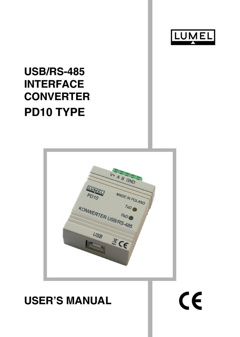
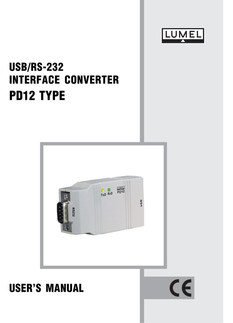
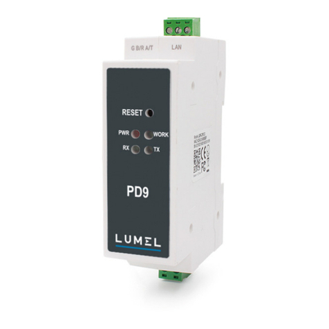
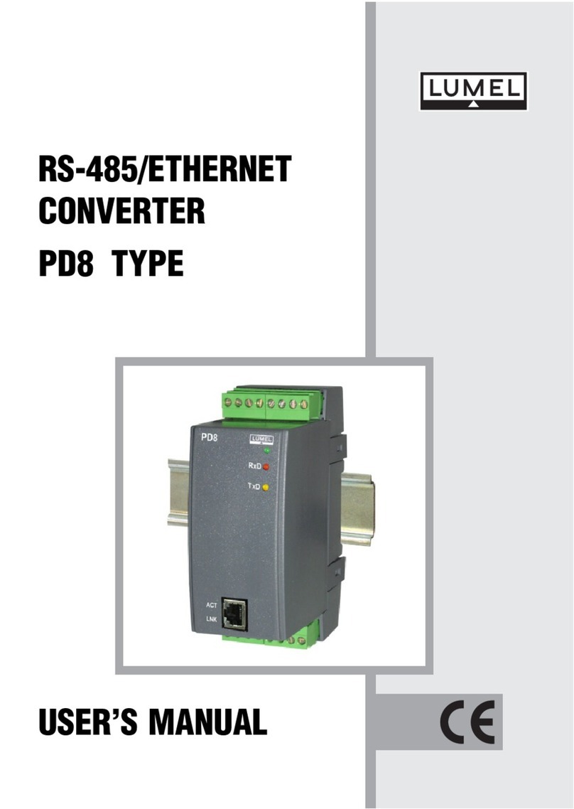
Lumel PD51 User manual

KONWERTER INTERFEJSÓW RS-232/RS-485
CONVERTER OF RS-232/RS-485 INTERFACES
PD51
INSTRUKCJA OBSŁUGI
USER’S MANUAL PL
EN

2
pl
1. ZASTOSOWANIE
Konwerter PD51 jest urządzeniem, które zamienia interfejs
RS-232 na przemysłowy RS-485. PD51 umożliwia zwiększenie zasię-
gu magistrali RS-485 i liczby urządzeń w sieci z magistralą RS-485.
Zapewnia automatyczne sterowanie kierunkiem przepływu danych.
Chociaż interfejs RS232 jest powszechnie akceptowany to
jednak z uwagi na ograniczony zakres i możliwości pracy, nie jest on
wykorzystywany w przemysłowych układach transmisji danych. Interfejs
RS-485 nie posiada takich ograniczeń ponieważ wykorzystuje różnicowy
sposób transmisji danych, co jest jego zaletą.
Konwerter dostępny jest w wykonaniu PD51-A – wykonanie
z optoizolacją do montażu na szynę.
2. ZESTAW KONWERTERA
W skład zestawu konwertera/repeatera PD51-A wchodzą:
• konwerter/repeater PD51-A 1 szt,
• instrukcja obsługi 1 szt,

3
pl
Rys. 1 Rysunek gabarytowy i montażowy konwertera PD51A.
6
PD51
RxD
TxD
12345
120
22,5
100
78910
3. INSTALOWANIE KONWERTERA PD51-A
Konwerter jest przewidziany do mocowania na wsporniku montażowym
35 mm (PN-EN 60715:2002) wg rysunku 1.

4
pl
Zasilanie oraz sygnały zewnętrzne należy podłączyć zgodnie z rysun-
kiem 2 oraz tablicą 1, w której opisano poszczególne wyprowadzenia.
Uwaga:
Należy zwrócić szczególną uwagę na prawidłowe podłączenie
sygnałów zewnętrznych (patrz tablica 1).
Rys. 2. Podłączenia elektryczne konwertera/repeatera PD51-A.
a) dla zasilania 85... 253 V a.c./d.c. oraz 20... 40 V a.c./d.c.
b) dla zasilania 7... 35 V d.c.
6
PD51
RxD
TxD
12345
78910
RS-232 RS-485
RS-485
ZAS.
85... ...253 V230
20... ...40 V24
6
PD51
RxD
TxD
12345
78910
RS-232 RS-485
RS-485
ZAS.
7... ...35 V24
a) b)

5
pl
Na płycie czołowej znajdują się trzy diody:
żółta (TxD) - sygnalizuje nadawanie danych przez RS-232 (w konguracji
konwertera) lub RS-485 (w konguracji repeatera),
czerwona (RxD) - sygnalizuje odbieranie danych przez RS-232
(w konguracji konwertera) lub RS-485 (w konguracji repeatera),
zielona - sygnalizuje załączenie zasilania.
Rysunek 3 przedstawia przykładowy sposób podłączenia konwertera PD51-
-A. Od strony interfejsu RS-485 konwerter może być podłączony do magistrali
RS-485 lub bezpośrednio do urządzenia z interfejsem RS-485.
A
Magistrala
RS-485
zasilanie
B
GND
GND
A
B
7 8 9 10
2345
6
1
PD51
Magistrala
RS-232
GND
GND
RxD TxD
TxD RxD
1
6
7
8
9
2
3
4
5
Rys 3. Przykład podłączenia konwertera PD51-A.
Opis wyprowadzeń konwertera/repeatera PD51-A
Opis wyprowadzenia
1 Linia TxD portu szeregowego RS-232
2 Linia RxD portu szeregowego RS-232
3 Linia GND interfejsów RS-232 i RS-485 (repeatera)
4 Linia A interfejsu RS-485 (repeatera)
5 Linia B interfejsu RS-485 (repeatera)
6, 7 Linie zasilania konwertera/repeatera
8 Linia GND portu szeregowego RS-485 z optoizolacją
9 Linia A interfejsu RS-485 z optoizolacją
10 Linia B interfejsu RS-485 z optoizolacją
Tablica 1
Nr
wyprowadzenia

6
pl
A
Magistrala
RS-485
zasilanie
B
GND
7 8 9 10
2345
6
1
PD51
GND
A
B
GND
A
B
Magistrala
RS-485
GND
A
B
Rys 4. przedstawia przykład podłączenia PD51-A pracującego jako
repeater (wzmacniacz sygnałów sieci).
Rys 4. Przykład podłączenia repeatera PD51-A.
4. OPIS DZIAŁANIA
Standard RS-485 umożliwia wymianę danych typu half duplex. Oznacza
to, że dane mogą być w jednej chwili albo nadawane albo odbierane.
Konstrukcja układu wewnętrznego w konwerterze umożliwia automa-
tyczne sterowanie kierunkiem przepływu danych. Nie ma więc potrzeby
stosowania dodatkowych sygnałów uzgodnień takich jak RTS. Konwer-
ter nie umożliwia klasycznego sterowania nadajnikiem interfejsu RS-485
poprzez dodatkowy sygnał RTS interfejsu RS-232.
Konwerter PD51 może pracować z maksymalną prędkością transmisji do
115,2 kb/s na liniach o długości do 400 m. Przy długości linii powyżej
800 m konwerter pracuje z prędkościami transmisji do 19,2 kb/s. Między
liniami A i B interfejsu RS-485 na końcach magistrali należy stosować
terminatory (rezystory). Wartość terminatorów należy dostosować do
aplikacji.
W środowisku o nieznanym poziomie zakłóceń zaleca się
przestrzeganie następujących zasad:
• nie zasilać konwertera/repeatera z sieci w pobliżu urządzeń wytwa-
rzających duże zakłócenia impulsowe,
• stosować ltry sieciowe dla grupy konwerterów/repeaterów obsługu-
jących ten sam obiekt,

7
pl
• do prowadzenia przewodów zasilających stosować ekrany metalowe
w postaci rurek lub oplotów, w których można prowadzić także przewód
uziemienia i ewentualnie przewody sieciowe,
• przyłączenia obwodów interfejsu komunikacyjnego prowadzić indy-
widualnie w ekranie jw. skręconymi przewodami,
• stosować ogólna zasadę, że przewody (wiązki) wiodące różne sygna-
ły powinny być prowadzone w jak największej odległości od siebie (nie
mniej niż 50 cm), a skrzyżowania takich wiązek wykonane pod kątem
90°.
5. DANE TECHNICZNE
Dane transmisyjne
- prędkość transmisji [bit/s] 1200, 2400; 4800; 9600; 19200;
38400; 57600; 115200
- sterowanie kierunkiem przepływu danych automatyczne
Moc pobierana przez konwerter 1,5 VA (PD51-A)
Znamionowe warunki użytkowania:
- napięcie zasilania PD51-A 7...35 V d.c. lub 20...40 V a.c./d.c.
lub 85...253 V a.c./d.c.
- częstotliwość napięcia zasilania PD51-A 40...50...440 Hz
- temperatura otoczenia 0...23...50°C
- wilgotność względna powietrza < 85%
- zewnętrzne pole magnetyczne < 400 A/m
- położenie pracy dowolne
Warunki magazynowania i transportu:
- temperatura otoczenia -20... 70°C
- wilgotność względna powietrza < 85%
- dopuszczalne wibracje sinusoidalne:
- częstotliwość 10...150 Hz
- amplituda przemieszczenia 0,35 mm

8
pl
Zapewniane stopnie ochrony:
- od strony obudowy IP 40
- od strony wyprowadzeń IP 20
Wymiary:
- PD51-A 22,5 120 98 mm
Masa:
- PD51-A 0,25 kg
Obudowa PD51-A do montażu na szynę
Kompatybilność elektromagnetyczna:
- odporność na zakłócenia według normy PN-EN 61000-6-2;2002(U)
- emisja zakłóceń według PN-EN 61000-6-4;2002(U)
Wymagania bezpieczeństwa wg PN-EN 61010-1:
- kategoria instalacji II
- stopień zanieczyszczenia 2
Maksymalne napiecie pracy względem ziemi:
- dla obwodów zasilania 300 V
- dla pozostałych obwodów 50 V

9
EN
1. APPLICATION
The PD51 converter is a digital device destined to convert the RS-232
interface into the industrial interface RS-485. It enables the increase of
the RS-485 bus range and the number of devices in the network with
a RS-485 bus.
It ensures the automatic steering of the data ow direction.
The RS-232 interface is commonly accepted but since it has a limited
range and restricted working possibilities, it is not used in industrial data
transmission systems. In almost automation systems and advanced
control systems, the RS-485 interface is used because it has not such
limitations and utilises the differential procedure for data transmission,
what is its main feature.
The PD51 converter is produced in version PD51-A - to be assembled
on a rail.
2. CONVERTER SET
The delivered set of PD51-A converter/ repeater includes:
- converter/repeater PD51-A............1 pc
- user’s manual................................1 pc

10
EN
Fig.1 overall and assembly drawing of PD51-A converter
6
PD51
RxD
TxD
12345
120
22.5
100
78910
3. INSTALLATION OF PD51-A CONVERTER
The converter is designed to be xed on a 35 mm rail (EN 60715), acc.
to the g.1.

11
EN
The supply and external signals should be connected in accordance with the
g. 2 and the table 1 in which particular outlets are described.
Note:
Special attention must be paid to the correct connection of
external signals (see table 1).
Fig. 2. Electrical connections of the PD51-A converter/repeater
a) for supply: 85...253 V a.c./d.c. and 20...40 V a.c./d.c.
b) for supply: 7...35 V d.c.
6
PD51
RxD
TxD
12345
78910
SUPPLY
RS-232 RS-485
RS-485
6
PD51
RxD
TxD
12345
78910
SUPPLY
RS-232
RS-485
RS-485
a) b)

12
EN
There are three diodes on the frontal plate:
yellow (TxD) - signalling the data transmission through RS-232 ( in
the converter conguration) or RS-485 (in the repeater conguration),
red (RXD) - signalling the data reception through RS-232 (in the
converter conguration) or RS-485 (in the repeater conguration),
green - signalling the supply connection.
Description of PD51-A converter/repeater outlets
Terminal No Terminal description
1 TxD line of the RS-232 serial port
2 RxD line of the RS-232 serial port
3 GND line of RS-232 and RS-485 interfaces (repeater)
4 A line of RS-485 interface (repeater)
5 B line of RS-485 interface (repeater)
6, 7 Supply line of the converter/repeater
8 GND line of the RS-485 serial port with optoisolation
9 A line of RS-485 interface with optoisolation
10 B line of RS-485 interface with optoisolation
Table 1
The g. 3. presents an exemplary way of PD51-A connection.
From the RS-485 interface side the converter can be connected to the
RS-485 bus or directly to the device with RS-485 interface.
A
RS-485
bus
supply
B
GND
GND
A
B
7 8 9 10
2345
6
1
PD51
RS-232
bus
GND
GND
RxD TxD
TxD RxD
1
6
7
8
9
2
3
4
5
Fig. 3. Example of PD51-A converter connection

13
EN
A
RS-485
bus
supply
B
GND
7 8 9 10
2345
6
1
PD51
GND
A
B
GND
A
B
RS-485
bus
GND
A
B
The g. 4. presents an example of PD51-A connection working as a
repeater
Fig. 4. Example of PD51-A repeater connection
4. DESCRIPTION OF OPERATION
The RS-485 standard enables the exchange of data of half duplex type.
This means that data can be transmitted or received in the same time.
The design of the internal system in the converter enables the automatic
steering of the data ow direction.
It is not necessary to apply additional handshake signals such as RTS. The
converter cannot make possible a classical steering of the RS-485 interface
transmitter through the additional RTS signal of the RS-232 interface.
The PD51 converter can work with a maximal baud rate up to 115.2
kb/s, in lines up to 400 m long. When the line length exceeds 800 m,
the converter works with a baud rate up to 19.2 kb/s.
Between A and B lines of the RS-485 interface, on bus ends, one should
use terminators (resistors). The terminator value should be readjusted
to the application.

14
EN
In the environment with unknown interference level it is
recommended to observe following principles:
• do not supply the converter/repeater from the network near
devices generating high impulse interference,
• use network lters for the converter/repeater group servicing the
same object,
• use metallic screens in the shape of tubes or braids to conduct
supplying wires. In these screens, one can also lead the earth
conductor, and if need be, network conductors,
• one should connect circuits of the communication interface
individually in a screen as above, by means of twisted wires,
• apply the general principle that wires (groups of wires) leading
different signals should be led in the farthest distance between
them (not less than 50 cm), and crossings of such wires or
groups of wires made at right angle.
5. TECHNICAL DATA
Transmision data:
- baud rate 1200, 2400, 4800, 9600, 19200,
38400, 57600, 115200 [bit/s]
- control of the data ow direction automatic
Power consumption by the converter:
- PD51-A 1.5 VA
Rated operating conditions:
- supply voltage of PD51-A 7... 35 V d.c.
or 20... 40 V a.c./d.c.
or 85... 253 V a.c./d.c.
- supply voltage frequency of PD51-A 45...50...440 Hz
- ambient temperature 0...23...50°C
- relative humidity < 85%
- external magnetic eld < 400 A/m
- work position any

15
EN
Storage and transport conditions:
- ambient temperature - 20... 70C
- relative humidity < 85%
- admissible sinusoidal vibrations:
- frequency 10...150 Hz
- displacement amplitude 0.35 mm
Ensured protection degree:
- by the housing IP 40
- from terminals side IP 20
Overal dimensions:
- PD51-A 22.5 120 100 mm
Weight:
- PD51-A 0.25 kg
Housing:
- PD51-A to be assembled on a rail
Electromagnetic compatibility:
- Immunity acc.to EN 61000-6-2
- emission acc.to EN 61000-6-4
Safety requirements acc. to EN 61010-1:
- installation category II
- pollution degree 2
Maximal phase-to-earth working voltage:
- for supply circuits 300 V
- for other circuits 50 V

PD51-07B, PD51-09B
60-006-00-00814
Informacja techniczna:
tel.: (68) 45 75 140, 45 75 141, 45 75 142, 45 75 145, 45 75 146
e-mail: [email protected]
LUMEL S.A.
ul. Słubicka 4, 65-127 Zielona Góra, Poland
tel.: +48 68 45 75 100, fax +48 68 45 75 508
www.lumel.com.pl
Pracownia systemów automatyki:
tel.: (68) 45 75 145, 45 75 145
Export department:
tel.: (+48 68) 45 75 130, 45 75 131, 45 75 132
e-mail: expor[email protected]
Calibration & Attestation:
e-mail: [email protected]
Technical support:
tel.: (+48 68) 45 75 143, 45 75 141, 45 75 144, 45 75 140
e-mail: expor[email protected]
Wzorcowanie:
tel.: (68) 45 75 163
e-mail: [email protected]
Realizacja zamówień:
tel.: (68) 45 75 150, 45 75 151, 45 75 152, 45 75 153, 45 75 154, 45 75 155
fax.: (68) 32 55 650
Table of contents
Languages:
Other Lumel Media Converter manuals
Popular Media Converter manuals by other brands

EEG
EEG HD490 manual

Datalogic
Datalogic ENC58-H14-PROG manual

LDT
LDT Digital-Professional Series Operating instruction

TeddyPardo
TeddyPardo Bluesound Node2i Quick start up guide

Digital Watchdog
Digital Watchdog Compressor DW-CP16 quick start guide

Power Electronics
Power Electronics SD750FR Hardware and installation manual

Optical Systems Design
Optical Systems Design OSD2166M Series Operator's manual

ReQuest Multimedia
ReQuest Multimedia VideoReQuest Protocol guide

HDTV Supply
HDTV Supply HDC-SP918CN user manual

Kramer
Kramer VM-4UHD quick start guide

Ross
Ross DED-8420 user manual

TR-Electronic
TR-Electronic DeviceNet C 65 Series user manual