1
IMPORTANT:
Go to www.extron.com for the complete
user guide, installation instructions, and
specifications before connecting the
product to the power source.
DANGER: This is an All UL Notations style. Use All UL Notations for all regulatory notations including
ATTENTION, NOTES, and TIPS. The word “DANGER” must be 10 points regardless of other font size used.
A statement in 75 bold that “<whatever> may result in Serious injury or death” must start a Danger statement.
WARNING: The word “WARNING” must be 10 points regardless of other font size used.
CAUTION: This is a caution sytle. The word “CAUTION” must be 10 points regardless of other font size used.
ATTENTION: The word “ATTENTION” may be the same font size as the rest of the attention statement.
NOTE: The word “NOTE” may be the same font size as the rest of the note statement.
NAV 10E 401 D and NAV 10E 201 D • Setup Guide
CLASS 1 LASER PRODUCT, see NAV 10E 401 D and NAV 10E 201 D User Guide at www.extron.com.
WARNING: The NAV 10E 401 D and NAV 10E 201 D output continuous invisible light (Class 1 rated), which may be harmful to
the eyes; use with caution.
• Do not look into the ber optic cable connectors or into the ber optic cables themselves.
• Plug the attached dust caps into the optical transceivers when the ber cable is unplugged.
AVERTISSEMENT : Le NAV 10E 401 D and NAV 10E 201 D émettent une lumière invisible en continu (équipement de classe 1)
qui peut être dangereuse pour les yeux ; à utiliser avec précaution.
• Ne pas xer directement les connecteurs optiques ou les câbles bre optique.
• Associez les bouchons anti-poussière à l’ensemble émetteur/récepteur optique lorsque le câble bre optique est débranché.
This guide provides instructions for an experienced installer to install the Extron NAV 10E 401 D and NAV 10E 201 D
streaming encoders and to make all connections. The Extron NAV encoder and one or more compatible decoders form an
AV distribution and switching matrix on a managed 10G IP network. The encoder fits in a standard US three-gang mud ring
or electrical junction box. The encoder ships with a three-gang mud ring and a decorator-style wallplate (white or black,
depending on the version ordered). The front panel faceplates are in white or black, as appropriate.
NOTE: For more information on any subject in this guide, see the NAV 10E 401 D and NAV 10E 201 D User Guide,
available at www.extron.com.
Features
HDMI IN HDMI OUT
E
STRM
HDMI HDCP
PWR
RESET
NAV 10G
ID
LNK
ACT
CONFIG
LAN - EXT
EEE
NAV 10E 401
only
Figure 1. NAV 10E 401 D Front Panel Features
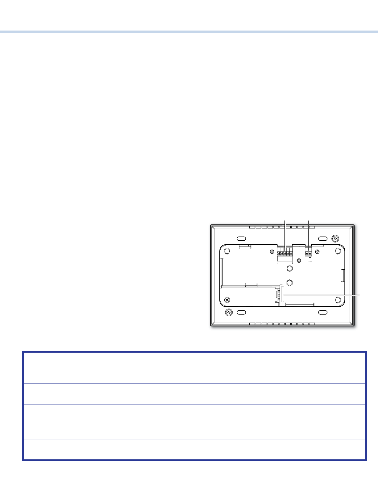
Front Panel
NOTES:
• Figure 1 shows a NAV 10E 401 D. The NAV 10E 201 D
is similar, the exception is lack of a NAV Extension port
(D).
• Items Cand Fare visible only when the faceplate is
removed.
Connectors
AHDMI input (IN) port —Connect an HDMI cable between
this port and the HDMI output port (or DVI port, with an
appropriate adapter) of the digital video source.
BHDMI output (OUT) port — Connect a display to this female
HDMI connector for local loop-through monitoring of the
source signal.
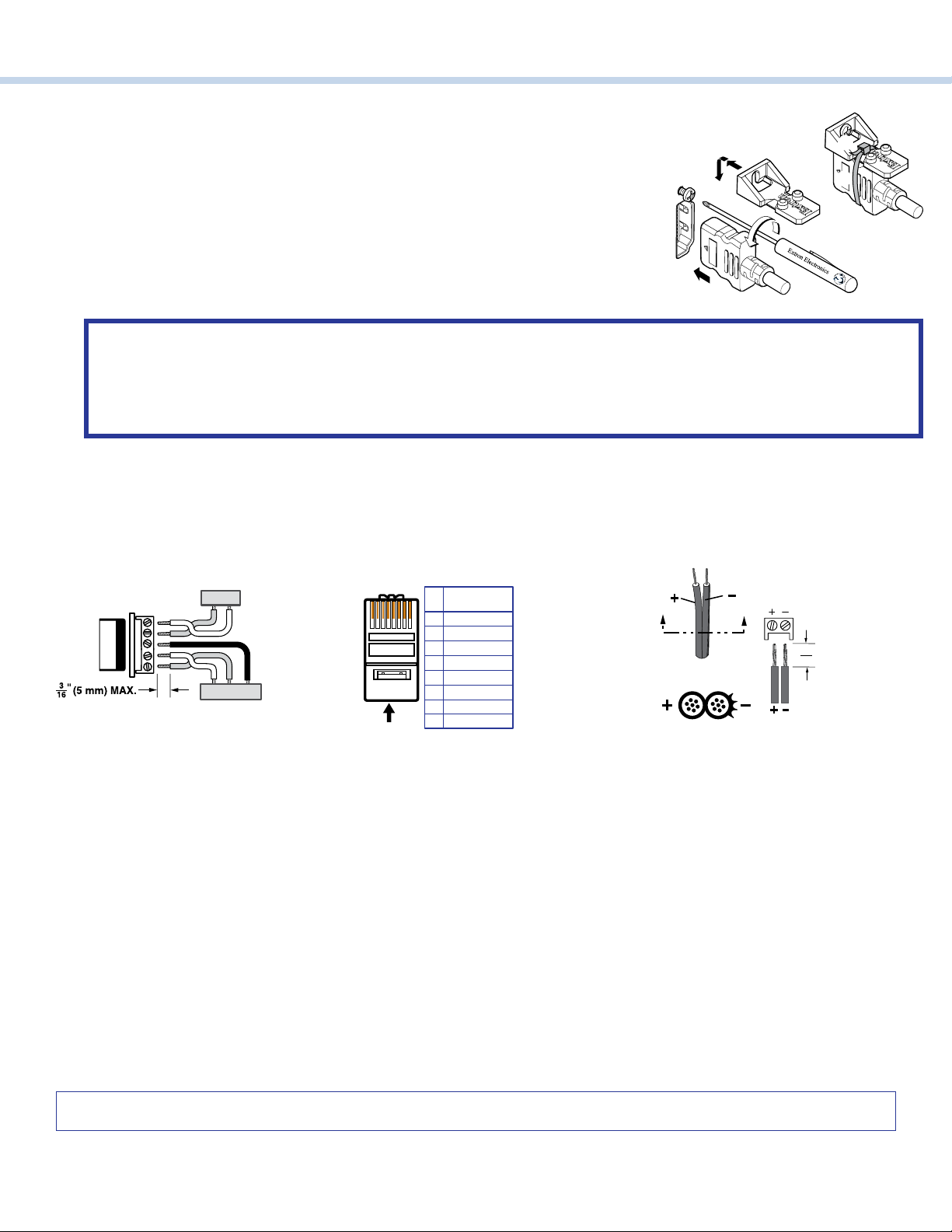
NOTE: See LockIt®Lacing Brackets on page 6 to securely fasten the HDMI connectors to the encoder for Aand B.
CConfiguration (CONFIG) port —Connect a PC into the encoder for configuration of the encoder. The port uses IP over
USB technology; the IP address is always 203.0.113.22 and CANNOT be changed. The Config port is also discoverable via
Toolbelt.
DLAN - Ext(ension) port (NAV 10E 401 D only) — If desired, connect another networked device to this port (see Ext
connector on page 8 to wire the connector). The port acts as a networked switch to the NAV 10G port (see Aon
page 2).