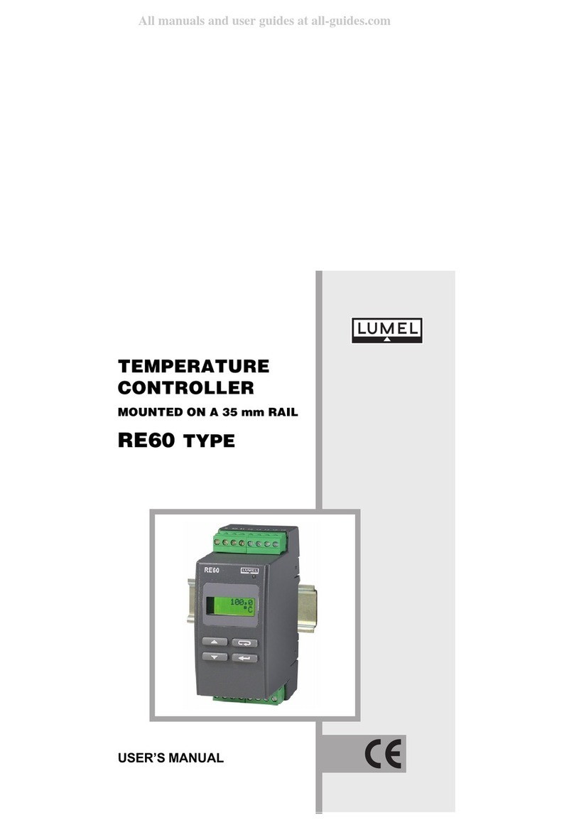
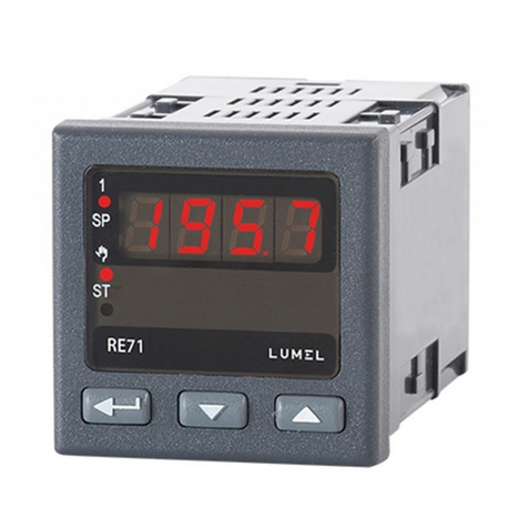
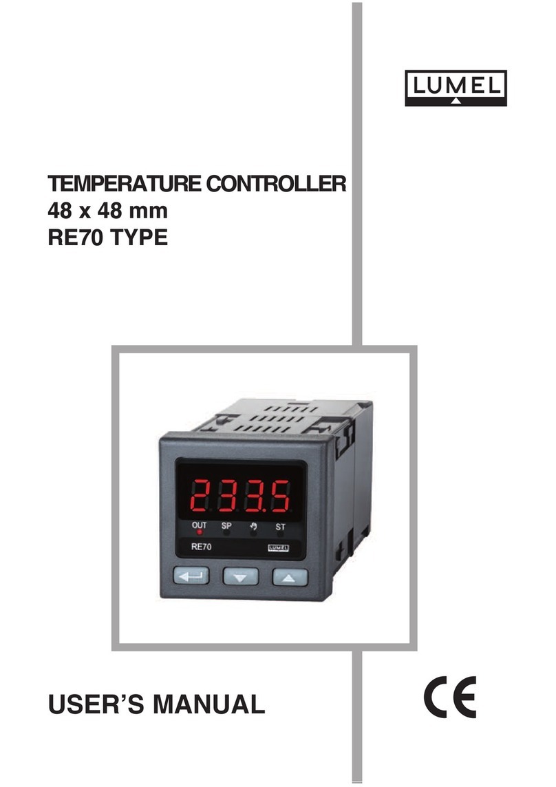
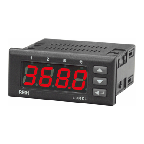
Lumel RE60 User manual

REGULATOR TEMPERATURY NA SZYNĘ 35 mm
TEMPERATURE CONTROLLER FOR DIN RAIL 35 mm
INSTRUKCJA OBSŁUGI - SZYBKI START
Pełna wersja instrukcji dostępna na
Full version of user’s manual available at
www.lumel.com.pl
USER’S MANUAL - QUICK START PL
EN
Zeskanuj mnie
Zeskanuj kod Scan the code

2
pl

3
pl
1. WYMAGANIA PODSTAWOWE,
l
l
l
l
l
l
Przymocowaæ regulator na wsporniku szynowym 35 mm wg
PN-EN 60715. Obudowa regulatora jest wykonana z samogasn¹cego
tworzywa sztucznego. Wymiary regulatora i sposób mocowania przed-
stawiono na rys. 1.

4
pl
Rys.1. Wymiary i sposób mocowania regulatora.
W œrodowisku o nieznanym poziomie zak³óceñ elektromagnetycznych
powinno siê przestrzegaæ nastêpuj¹cych zasad:
- nie zasilaæ regulatora z sieci w pobli¿u urz¹dzeñ wytwarzaj¹cych zak³ócenia
impulsowe i nie stosowaæ wspólnych z nimi obwodów uziemiaj¹cych,
- stosowaæ filtry sieciowe,
- do prowadzenia przewodów zasilaj¹cych stosowaæ ekrany metalowe
w postaci rurek lub oplotów,
- przewody doprowadzaj¹ce sygna³ pomiarowy powinny byæ
skrêcone parami, a dla czujników oporowych w po³¹czeniu
trójprzewodowym skrêcane z przewodów o tej samej d³ugoœci,
przekroju i rezystancji oraz prowadzone w ekranie jw.,
- wszystkie ekrany powinny byæ uziemione lub pod³¹czone do
przewodu ochronnego, jednostronnie jak najbli¿ej regulatora,
- stosowaæ ogóln¹ zasadê, ¿e przewody wiod¹ce ró¿ne sygna³y
powinny byæ prowadzone w jak najwiêkszej odleg³oœci od siebie
(nie mniej ni¿ 30 cm), a skrzy¿owanie tych wi¹zek wykonywane
jest pod k¹tem 90o.

5
pl
Po za³¹czeniu zasilania, co sygnalizuje zielona dioda, regulator
wyœwietla typ i wersjê programu.
Po oko³o trzech sekundach regulator przechodzi do regulacji wed³ug
ustawionych parametrów. Wyœwietla wartoœæ mierzon¹, wartoœæ zadan¹
oraz znaczniki za³¹czonych wyjœæ.
Fabrycznie ustawiony jest algorytm regulacji za³¹cz-wy³¹cz z histerez¹ 2oC.
Na wyœwietlaczu mo¿e byæ komunikat znakowy informuj¹cy o nie-
prawid³owoœciach (tab. 2 - patrz pełna wersja instrukcji obsługi, dostępna
na www.lumel.com.pl).
Zmiana wartoœci zadanej
Wejœcie w tryb zmiany wartoœci zadanej nastêpuje po naciœniêciu przy-
cisku lub . Sposób zmiany wartoœci zadanej jest pokazany
na rys.5. Jeœli wartoœæ zadana nie zostanie zaakceptowana w ci¹gu
30 sekund od ostatniego naciœniêcia przycisku lub regulator
automatycznie przechodzi do trybu normalnej pracy bez wprowadzenia
nowej wartoœci zadanej.

6
pl
PrOGrAMOWANIE PArAMETróW
Rys.5. Zmiana wartoœci zadanej.
lub
Obs³uga regulatora jest przedstawiona na rys. 6. Po naciœniêciu
i przytrzymaniu przez co najmniej 2 sekundy przycisku mo¿liwe
jest programowanie parametrów. Przechodzenie pomiêdzy parametrami
odbywa siê za pomoc¹ przycisków i . Niektóre parametry mog¹
byæ niewidoczne - uzale¿nione jest to od wyboru algorytmu regulacji czy
konfiguracji alarmów. Opis parametrów zawiera tab. 1- patrz pełna wersja
instrukcji obsługi, dostepna na www.lumel.com.pl. Powrót do normalnego
trybu pracy nastêpuje po naciœniêciu przycisku lub automatycznie
po up³ywie 30 sekund od ostatniego naciœniêcia przycisku.

7
pl
rozpoczêcie zmian
anulowanie zmian
lub
zwiêkszenie
wartoœci
zmniejszenie
wartoœci
akceptacja zmian
3sek
poprawny
kod?
N
T
N
T
zwiêkszenie
wartoœci lub
nastêpny parametr
wyliczeniowy
zmniejszenie
wartoœci lub
poprzedni parametr
wyliczeniowy
aktywny
kod dostêpu
rozpoczêcie zmian
anulowanie zmian
akceptacja zmian
nastêpny
parametr
poprzedni
parametr
przytrzymany
podgl¹d sygna³u
steruj¹cego tryb normalnej pracy tryb zmiany
wartoœci zadanej
tryb zmiany
parametrów
Rys.6. Menu obsługi
regulatora

8
pl
5. DANE TECHNICZNE
Natê¿enie pr¹du p³yn¹cego przez Pt100: 220 A
Czas pomiaru: 0,5 s
Wykrywanie b³êdu w obwodzie pomiarowym:
- termoelement, Pt100: przekroczenie zakresu pomiarowego
Rodzaje wyjϾ:
- przekaŸnikowe: styki beznapiêciowe zwierne
obci¹¿alnoœæ maksymalna:
napiêciowa: 250 V a.c., 150 V d.c.
pr¹dowa: 5 A 250 V a.c., 5 A 30 V d.c.
obci¹¿enie rezystancyjne 1250 VA, 150 W
- binarne napiêciowe: napiêcie 5 V
(bez izolacji od strony czujnika) rezystancja ograniczaj¹ca pr¹d 66
Sposób dzia³ania wyjœæ:
- rewersyjne: dla grzania - wprost: dla ch³odzenia
Sygnalizacja:
- aktywnego wyjœcia: symbol na wyœwietlaczu LCD
- aktywnego alarmu: symbol na wyœwietlaczu LCD i dioda LED
Typ czujnika/wejœcia Oznaczenie Zakres B³¹d podstawowy
[°C] [°C]
Pt100
wg PN-EN 60751+A2 Pt100 -50...100 0,8
Pt100 Pt100 0...250 1,3
Pt100 Pt100 0...600 3,0
Fe-CuNi
wg PN-EN 60584-1 J 0...250 3,0
Fe-CuNi J 0...600 4,0
Fe-CuNi J 0...900 5,0
NiCr-NiAl
wg PN-EN 60584-1 K 0...600 4,0
NiCr-NiAl K 0...900 5,0
NiCr-NiAl K 0...1300 6,0
PtRh10-Pt
wg PN-EN 60584-1 S 0...1600 7,0

9
pl
Znamionowe warunki u¿ytkowania:
- napiêcie zasilania: 230 V a.c. ±10%; 110 V a.c. ±10%; 24 V a.c. ±10%;
8...72 V d.c.
- czêstotliwoœæ napiêcia zasilania a.c.: 50/60 Hz
- temperatura otoczenia: 0...23...50 °C
- temperatura przechowywania: -20...+70 °C
- wilgotnoœæ wzglêdna powietrza < 85 % (bez kondensacji pary wodnej)
- zewnêtrzne pole magnetyczne < 400 A/m
- czas wstêpnego nagrzewania: 30 min
- po³o¿enie pracy: dowolne
Pobór mocy < 3 VA
Wymiary: 45 x 100 x 120 mm Masa < 0,3 kg
Mocowanie na wsporniku szynowym 35 mm
Stopieñ ochrony zapewniany przez obudowê: IP40 wg PN-EN 60529
B³êdy dodatkowe w znamionowych warunkach u¿ytkowania
spowodowane:
- zmian¹ temperatury otoczenia 100% b³êdu podstawowego /10 K.
Wymagania bezpieczeñstwa wg PN-EN 61010-1
- kategoria instalacji: III
- stopieñ zanieczyszczenia: 2
- maksymalne napiêcie pracy wzglêdem ziemi:
- dla obwodu zasilania, wyjœcia 300 V
- dla obwodów wejœciowych 50 V
KompatybilnoϾ elektromagnetyczna
- odpornoœæ na zak³ócenia elektromagnetyczne wg normy PN-EN 61000-6-2
- emisja zak³óceñ elektromagnetycznych wg normy PN-EN 61000-6-4

10
EN
SAFETY
Observations Concerning the Operational Safety:
l
l
l
l
l
l
l
Fix the controller on the 35 mm rail acc. to EN 60715.
The controller housing is made of a self-extinguishing plastics.
Dimensions of the controller and the fixing way is presented on the fig.1

11
EN
RE60
120
45
35
100
120,7
93
41
lock
Fig.1. Dimensions and fixing way of the controller
In order to obtain a full fastness against electromagnetic noise in
an environment with unknown noise level, it is recommended to observe
following principles:
- do not supply the controller from the network, in the proximity of devices
generating high pulse noise and do not apply common earthing circuits,
- apply network filters,
- apply metallic shields in the shape of tubes or braids to conduct supplying
wires,
- wires leading measuring signals should be twisted in pairs, and for
resistance sensors in 3-wire connection, twisted of wires of the same
length , cross-section and resistance, and led in a shield as above,
- all shields should be one-side earthed or connected to the protective
wire, the nearest possible to the controller,
- apply the general principle, that wires leading different signals should
be led at the maximal distance between them (no less than 30 cm), and
the crossing of these group of wires made at right angle (90o).

12
EN
After connecting the supply, what is signalled by the green diode,
the controller displays the type and program version.
After ca three seconds, the controller transits to the control acc. to set
parameters. The controller displays the measured value, the set point
and annunciators of connected outputs.
The on-off control algorythm with hysteresis 2oC is set by the
manufacturer.
A character message informing about abnormalities can be shown
on the display (tab. 2 - see version of service manual, available at
www.lumel.com.pl ).
Measured
value (PV)
Set point
(SP)
Annunciator
of alarm 2
Annunciator
of alarm 1
Annunciator
of the control
output
Change of the set point
The entry into the set point change mode follows after pressing the
or push-button. The way to change the set point is shown
on the fig. 5. If the set point is not accepted within 30 seconds from
the last pressure of the or push-button, the controller
transits automatically into the normal working mode without the
introduction of a new set point.

13
EN
PArAMETErS
The controller service is presented on the fig.6. after pressing and hol-
ding the push-button during at least 2 seconds, the programming
of parameters is possible. The transition between parameters is carried
out by means of and push-buttons. Some parameters can be
invisible - it depends on the choice of the control algorythm or the alarm
configuration. The table 1 (see full version of service manual, available
at www.lumel.com.pl) includes the description of parameters. The return
to the normal working mode follows after pressing the push-button
or automatically after 30 seconds from the last push-button pressure.
or
Beginning of changes
Acceptation of changes
Cancellation of
changes
Increase
the value
Decrease
the value

14
EN
Start of changes
Cancellation
of changes
or
Increase
of value
Decrease
of value
Acceptation
of changes
3sec
Correct
code?
N
T
N
T
Increase of value
or next
evaluated parameter
Decrease of value
or previous
evaluated parameter
Active
access code
Start of changes
Cancellation
of changes
Acceptation
of changes
Next
parameter
Previous
parameter
Held up
Monitoring of the
control signal Normal working mode Set point
change mode
Parameter
change mode
Fig.6. Diagram of controller
servicing menu

15
EN
Input signals and measuring ranges for inputs Table A
Sensor type/inputs Marking Range Basic error
[°C] [°C]
Pt100
acc.to EN 60751+A2 Pt100 -50...100 0.8
Pt100 Pt100 0...250 1.3
Pt100 Pt100 0...600 3.0
Fe-CuNi
acc.to EN 60584-1 J 0...250 3.0
Fe-CuNi J 0...600 4.0
Fe-CuNi J 0...900 5.0
NiCr-NiAl
acc.to EN 60584-1 K 0...600 4.0
NiCr-NiAl K 0...900 5.0
NiCr-NiAl K 0...1300 6.0
PtRh10-Pt
acc.to EN 60584-1 S 0...1600 7.0
Current flowing through Pt100: 220 A
Measurement time: 0,5 s
Detection of error in the measuring circuit:
- thermocouple, Pt100: overflow of the measuring range
Kinds of outputs:
- relay: voltageless make contacts
maximal load:
voltage: 250 V a.c., 150 V d.c.
current: 5 A 250 V a.c., 5 A 30 V d.c.
resistance load: 1250 VA, 150 W
- logic voltage: 5 V
(without isolation from the sensor side) resistance limiting the current: 66
Way of output operation:
- reverse for heating - direct for cooling
Signalling:
- active output: symbol on the LCD display
- active alarm: symbol on the LCD display and LED diode

16
EN
Rated operating conditions:
- supply voltage: 230 V a.c. ±10%; 110 V a.c. ±10%; 24 V a.c. ±10%
18...72 V d.c.
- frequency of supply voltage: 50/60 Hz
- ambient temperature: 0...23...50 °C
- storage temperature: -20...+70 °C
- related air humidity < 85 % (without condensation)
- external magnetic field < 400 A/m
- preheating time: 30 min
- work position: any
Power consumption < 3 VA
Dimensions: 45 x 100 x 120 mm Weight < 0,3 kg
Fixing: on a 35mm rail
Protection degree ensuring by the house: IP40 acc. to EN 60529
Additional errors in rated operating conditions:
- changes of the ambient temperature 100% of the basic error /10 K.
Security requirements acc. to EN 61010-1
- installation category III
- pollution level 2
- maximal phase-to-earth working voltage:
- for the supplying circuit, outputs 300 V
- for input circuits 50 V
Electromagnetic compatibility:
- immunity acc. to EN 61000-6-2
- emissions acc. to EN 61000-6-4

PL EN
Wykonaæ pod³¹czenia elektryczne do listew zaciskowych a nastêpnie
listwy wcisn¹æ do gniazd regulatora.
Carry out electrical connections to the terminal strips and next insert strips into
controller sockets.
Rys.2. Widok listew pod³¹czeniowych regulatora.
/supply
/ input signals
Fig.2. View of controller connection strips

pl EN
18
termorezystor Pt100
w uk³adzie 2-przewodowym
Rys.3. Pod³¹czenie sygna³ów wejœciowych.
zasilanie
Rys.4. Pod³¹czenie zasilania i obwodu obci¹¿enia
termorezystor Pt100
w uk³adzie 3-przewodowym termoelement
wyjœcie 1 -
przekaŸnik
wyjœcie
1 - binarne
napiêciowe
do sterowania
SSR
alarm 1 -
przekaŸnik alarm 2 -
przekaŸnik
Jumper
Fig.3. Connection of input signals
Pt100 thermoresistor
in a two-wire system Pt100 thermoresistor in a
three-wire system thermocouple
zasilanie/
supply zasilanie/
supply zasilanie/
supply zasilanie/
supply
odbiornik / load
odbiornik / load
odbiornik / load
odbiornik / load
Supply Output 1
- relay
Output 1 - logic
voltage for
SSR control
Output 1
- relay
Alarm 2
- relay
Fig.4. Connection of the supply and load circuit

19
EN

RE60-07A
RE60-09A
Informacja techniczna:
tel.: (68) 45 75 306, 45 75 180, 45 75 260
e-mail: [email protected]
Realizacja zamówień:
tel.: (68) 45 75 207, 45 75 209, 45 75 218, 45 75 341
fax.: (68) 32 55 650
LUMEL S.A.
ul. Sulechowska 1, 65-022 Zielona Góra, Poland
tel.: +48 68 45 75 100, fax +48 68 45 75 508
www.lumel.com.pl
Pracownia systemów automatyki:
tel.: (68) 45 75 228, 45 75 117
Wzorcowanie:
tel.: (68) 45 75 161
e-mail: [email protected]
Export department:
tel.: (+48 68) 45 75 139, 45 75 233, 45 75 321,
45 75 386, 45 75 353
fax.: (+48 68) 32 54 091
e-mail: expor[email protected]
Calibration & Attestation:
tel.: (68) 45 75 161
e-mail: [email protected]
Other manuals for RE60
3
Table of contents
Languages:
Other Lumel Temperature Controllers manuals
Popular Temperature Controllers manuals by other brands

Leviton
Leviton 23A00-1 Installation instructions and user guide

Elotech
Elotech R4000 Description and operating manual

KWE
KWE Versatronik COMO OT operating manual

Honeywell
Honeywell MICRONIK 200 R7426A Installation & start-up instructions

Sub-Zero
Sub-Zero SZ-7552-P operating instructions

Chromalox
Chromalox 8003 user manual