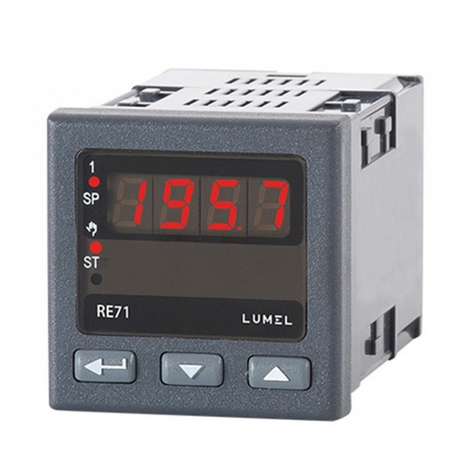
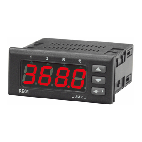
Lumel RE01 User manual

1
1
TEMPERATURE CONTROLLER 76x34 mm
RE01
USER’S MANUAL

2
2

3
3
Contents
1.APPLICATION ........................................................................ 5
2.CONTROLLER SET................................................................... 5
3.FUNDAMENTAL REQUIREMENTS, OPERATIONAL SAFETY ................... 6
4.ASSEMBLY ........................................................................... 6
4.1 INSTALLATION OF THE CONTROLLER ....................................... 6
4.2 ELECTRICAL CONNECTIONS................................................... 8
4.3 INSTALLATION RECOMMENDATIONS ....................................... 8
5.COMMENCEMENT OF OPERATION................................................ 9
6.OPERATION ......................................................................... 11
6.1 PROGRAMMING THE CONTROLLER’S PARAMETERS....................12
6.2 PROGRAMMING MATRIX ..................................................... 13
6.3 CHANGE OF THE SETTING ....................................................14
6.4 DESCRIPTION OF PARAMETERS ............................................15
7.CONTROLLER INPUTS AND OUTPUTS .......................................... 20
7.1 MEASUREMENT INPUT........................................................ 20
7.2 BINARY INPUT..................................................................20
7.3 OUTPUTS........................................................................ 20
8.CONTROL ............................................................................ 21
8.1 ON-OFF ALGORITHM .......................................................... 21
8.2 SMART PID INNOVATIVE ALGORITHM ..................................... 21
8.2.1 PULSE REPETITION PERIOD................................................ 22
8.2.2 SELF-TUNING................................................................. 22
8.2.3 PROCEDURE TO FOLLOW WHEN THE PID CONTROL IS UNSATISFACTORY ...25
9.ALARM AND SOUND ALARM ..................................................... 26
10.ADDITIONAL FUNCTIONS........................................................28
10.1 DISPLAY OF THE CONTROL SIGNAL .......................................28
10.2 MANUAL CONTROL ........................................................... 28
10.3 FACTORY SETTINGS.......................................................... 28

4
4
11.PROGRAMMING INTERFACE....................................................29
11.1 INTRODUCTION................................................................ 29
11.2 ERROR CODES................................................................. 29
11.3 REGISTER MAP................................................................ 29
12.ERROR SIGNALLING.............................................................. 37
13.TECHNICAL SPECIFICATION..................................................... 38
14.CONTROLLER DESIGN CODE.................................................... 41
The manual applies to the controller with software v1.02 or higher.

5
5
1. APPLICATION
Controller RE01 is designed to control temperature. It cooperates directly
with resistance-type sensors Pt100, Pt1000 and NTC.
The controller has one output for on-off control and one output for alarm
signalling. The on-off control employs the PID or on-off algorithm. For the
on-off control, the minimum on and off times for the output may be set.
The control output has a changeover contact and allows for the direct
control of low-power objects.
An innovative SMART PID algorithm is implemented in the controller.
In addition, the controller has a binary input to control the controller’s fun-
ctions and an internal sound signalling device.
2. CONTROLLER SET
The delivered controller set is composed of:
1. controller......................................... 1 piece
2. contact with 7 screw terminals........ 1 piece
3. contact with 3 screw terminals........ 1 piece
4. clamp for on-board mounting.......... 4 piece
5. gasket ............................................. 1 piece
6. user’s manual ................................. 1 piece
7. warranty card.................................. 1 piece

6
6
3. BASIC REQUIREMENTS, OPERATIONAL
SAFETY
In the safety service scope, the controller meets to requirements of the
EN 61010-1 standard.
Observations Concerning the Operational Safety:
• The assembly and installation of electrical connections shall be
performedbyapersonqualiedfortheassemblyofelectricaldevices.
• Check if the connections are made correctly before powering on the
controller.
• Power off the controller and disconnect measuring circuits before
removing the controller’s housing.
• The removal of the controller’s housing during the validity of the war-
rantyagreementnulliestheagreement.
• The devices is designed for installation and use in industrial, electro-
magnetic environmental conditions.
• Theinstallationshouldbettedwithaswitchorcircuit-breakerlocated
near the device, easily accessible to the operator and with appropriate
marking.
4. INSTALLATION
4.1. Controller Installation
Attach the controller to the board with four screw mounts
in line with Fig. 1. The hole in the board should be 71+0.7 x 29+0.6 mm.
The board material may be up to 15 mm thick.

7
7
Fig. 1. Attaching the controller
Fig. 2. Controller dimensions.
The controller’s dimensions are shown on Fig. 2.

8
4.2. Electrical Connections
The controller has two disconnectable strips with screw terminals.
One strip allows for the connection of power supply and output
with a wire up to 2.5 mm2in size and the other strip for the connection
of input signals with a wire up to 1.5 mm2in size.
Fig. 3. View of the controller’s connection strips.
4.3. Installation recommendations
To obtain full resistance to electromagnetic interference,
observe the following rules:
• do not power the controller from the mains near equipment genera-
ting impulse interference and do not use common earthing circuits
for them,
• uselinelters,
• measuring signal input wires should be screened twisted pairs and
wires for resistance sensor in three-wire systems formed by screened
twisted wires with the same length, size and resistance,
• all the screens should be earthed or connected to a protective cable,
on one side, as close to the controller as possible,
• follow the general principle that wires which transmit different signals
should run as far from each other as possible (no less than 30 cm)
and bundles should cross each other at the angle of 90o.

9
5. Commencement of operation
Fig. 4. View of the controller’s front panel.
Description of the controller
Power on
Once powered on, the controller performs a display test, shows re01,
software version and then the measured value.
The display may show a sign message on irregularities (see Table no. 13).
The on-off control algorithm with hysteresis 2.0°C is factory set.
Change of the set point
To display the set point, press or , the dot for the last
digit lights up then. To change the set point, press again or
(Fig.5).Thedotashestosignalthestartofchange.Accept
the new set point with within 30 seconds from the last pressed
or ; otherwise the controller changes over to display
the measured value with the previously set-up set point.

10
Fig. 5. Changing the set point.

11
6. OPERATION
Fig. 6 shows the operation of the controller.
Fig. 6. Controller operation menu

12
12
6.1. Programming of controller parameters
Press and hold for approx. 2 seconds to enter
the programming matrix. The programming matrix may be protected
with an access code. If a wrong code is inserted, one may only view
the settings without changing them.
Fig. 7 shows the navigation matrix in the programming mode.
To go from one level to another, use or and to select
a level, use . Once the level is selected or are
used to navigate among parameters. In order to change the parameter
setting, follow point Change of the setting. To exit the selected level,
go from parameter to parameter u til the symbol [. . .] appears
and press . To exit the programming matrix for the normal
operation mode, go from level to level until the symbol [. . .] appears and
press .
Some parameters of the controller may be hidden,
depending on the current conguration. The parameters are
described in Table no. 1. 30 seconds from the last button pressed,
the device returns automatically to the normal operation mode.

13
13
6.2. Programming Matrix
Fig. 7. Programming matrix
inp
Input
parame-
ters
u ni t
Unit
in.ty
Input
type
r-li
Line resi-
stance
dp
Decimal
point
position
5Hif
Measu-
red value
shift
bNin
Binary
input
function
. . .
Go one
level up
outp
Output
parame-
ters
out1
Output 1
congu-
ration
out2
Output
2 con-
gura-
tion
. . .
Go
one level
up
ctrl
Control
parame-
ters
alg
Control
algorit-
hm
type
Control
type
defr
Defrost
function
Dmod
Defrost
function
ope-
ration
mode
Dtim
Defrost
dura-
tion
Dsp
Defrost
termi-
nation
tempe-
rature
Ddur
Defrost
switching
on
interval
Hy
Hyste-
resis
Ton
Output
minimum
on time
Toff
Output
minimum
off time
sTlo
Lower
threshold
for self-
-tuning
sTHi
Upper
threshold
for self-
-tuning
Yfl
Sensor
failure
control
signal
. . .
Go
one level
up
pid
PID
parame-
ters
pb
Propor-
tional
band
ti
Integra-
tion Time
constant
td
Derivati-
ve time
constant
y0
Control
signal
adjust-
ment, for
P/PD-type
control
to
Pulse
repetition
period
. . .
Go
one level
up
alar
Alarm
parame-
ters
a!sp
Absolute
alarm
1 set
point
a!du
Devia-
tion from
relative
alarm
1 set
point
a!Hy
Alarm 1
hyste-
resis
a!lt
Alarm 1
memory
a@sp
Absolute
alarm 2
set point
a@du
Deviation
from
relative
alarm 2
set point
a@Hy
Alarm 2
hysteresis
A@
lt
Alarm
2 me-
mory
. . .
Go
one
level
up
spp
Set-point
value
parame-
ters
spl
set point
setting
lower
limit
spH
set point
setting
upper
limit
. . .
Go
one level
up
seru
Service
parame-
ters
seCU
Access
code
sTfn
Self-
-tuning
function
bufn
Buzzer
function
. . .
Go one
level up
. . .
Exit
from
menu

14
14
6.3. Change of the setting
To start changing the parameter setting, press while
the parameter name is displayed. Press and to select
the setting and press to accept it. A change is cancelled when
you press and at the same time or automatically after
30 seconds from the last button pressed.
Fig. 8 shows how to change settings.
Fig. 8. Changing the settings of numerical and text parameters.

15
15
List of confi guration parameters Table 1
6.4. Parameter Description
A list of parameters is given in Table no. 1.
Parameter
symbol
Parameter
description
Manufac-
turer
setting
Range of parameter changes
inp – Input parameters
unit Unit qC qC: Celsius degrees
qf: Fahrenheit degrees
iNty Input range 1) pt1 p1a: Pt100 (-50...100 °C)
p1b: Pt1000 (0...250 °C)
p1c: Pt100 (0...600 °C)
p10a: Pt1000 (-50...100 °C)
p10b: Pt1000 (0...250 °C)
p10c: Pt1000 (0...600 °C)
ntc: Ntc (-40...100 °C)
r-li Line resistance
for sensor
Pt100 2)
0.0 0.015.0
dp Position of
the main input
decimal point
1-dp 0-dp: without decimal point
1-dp: 1 decimal place
sHif
Measured va-
lue shift of the
main input
0,0 °C
(0,0 °F)
-100,0...100,0 °C
(-180,0...180,0 °F)
bNin
Binary input
function
none
none: no function
stop: control stop
rSal: alarm reset
out: output control
KlCk: keyboard lock
defr: defrost function on
(reaction to accretion

16
16
outp – Output parameters
out1 Output 1
conguration y
off: switched off
Y: control dignal
AHi: absolute higher alarm
Alo: absolute lower alarm
dwHi: relative higher alarm
dwlo: relative lower alarm
dwin: relative internal alarm
dwou: relative external alarm
biNd: direct control through
binary input
biNi: inverse control through
binary input
out2 Output 2
conguration off
off: switched off
AHi: absolute higher alarm
Alo: absolute lower alarm
dwHi: relative higher alarm
dwlo: relative lower alarm
dwin: relative internal alarm
dwou: relative external alarm
biNd: direct control through
binary input
biNi: inverse control through
binary input
defr:output controlled during
defrost
ctrl – Control parameters 3)
alg Control algo-
rithm oNof oNof: on-off control algorithm
pid: PID control algorithm
type Control type inu dir: direct control (cooling)
inu: inverse control
(heating)
defr Defrost function
11) 13) off
off: defrost function switched off
auto: defrost is switched on
atspeciedtimeinterval
(Ddur parameter)
hand: defrost function is
manually switched on
Dmod
Defrost function
operation mode
13)
time
time: defrost for a period of
time set by Dtim
parameter
temp: defrost until temperature
set by Dsp parameter is
reached 12)

17
17
Dtim Defrost duration
13) 21...10 h
Dsp Defrost tempe-
rature 13)
6.0 °C
(42.8 °F)
0.0...0.0 °C
(32.0...50.0 °F)
Ddur
Time interval
for defrost
switching on 13)
24 10...168 h
Hy Hysteresis 4) 2.0 °C
(3.6 °F)
0.2...100.0 oC
(0.2...180.0 oF)
Ton Output 1 mini-
mum on time 4)
0 0...999 s
Toff Output 1 mini-
mum off time 4)
0 0...999 s
sTlo Lower threshold
for self-tuning 5)
-50.0 °C
(-58.0 °F)
MIN…MAX 6)
sTHi Upper threshold
for self-tuning 5)
100.0 °C
(212.0 °F)
MIN…MAX 6)
Yfl
Control output
control signal
for sensor
failure 10)
0 0.0...100.0%
pid – PID parameters 7)
pb Proportional
band
30.0 °C
(54.0 °F)
0.1...550.0 oC
(0.1...990.0 oF)
ti Integration time
constant
300 0...9999 s
td Derivative time
constant
60.0 0.0...2500 s
y0 Control signal
adjustment, for
P or PD-type
control
0.0 0...100.0 %
to Pulse repetition
period 5)
20.0 5.0...99.9 s

18
18
alar – Alarm parameters 8)
a1.sp Set point value
for absolute
alarm1
0.0 °C
(32.0 °F) MIN...MAX 6)
a1.du Deviation from
set point for
relative alarm 1
2.0 °C
(3.6 °F) See Table no. 3
a1.Hy Hysteresis for
alarm 1
1.0 °C
(1.8 °F)
0.2...100.0 °C
(0.2...180.0 °F)
a1.lt Alarm 1
memory off off: disabled
on: enabled
a#sp Set point for ab-
solute alarm 2
0.0 °C
(32.0 °F) MIN...MAX 6)
a#du Deviation from
set point for
relative alarm 2
2.0 °C
(3.6 °F) See Table no. 3
a#Hy Hysteresis for
alarm 2
1.0 °C
(1.8 °F)
0.2...100.0 °C
(0.2...180.0 °F)
a#lt Alarm 2 memory off off: disabled
on: enabled
spp – Set point parameters
spl Set point setting
lower limit
-50.0 °C
(-58.0 °F) MIN...MAX 6)
spH Set point setting
upper limit
100.0 °C
(212.0 °F) MIN...MAX 6)
seru – Service parameters
seCU Access code 9) 0 0...9999
sTfn Self-tuning
function on off: locked
on: available
bwfn Sound signalling
function on off: disabled
on: enabled

19
19
1) Parameter changeable depending on the performance code.
2) Parameter visible only with Pt100-type sensors.
3) Parameter group visible only when the output is set to the control signal.
4) Parameter visible only when the control algorithm is set as on-off.
5) Parameter visible only when the control algorithm is set as PID
6) See Table no. 2.
7) Parameter group visible only when the control algorithm is set as PID.
8) Parameter group visible only when the output is set to alarm.
9) Parameter hidden when parameters are viewed in the read-only mode.
10) Parameter visible only when the output 1 function is set to y:
control signal. For control with alg = oNof and Yfl <= 50%
the control signal h = 0%, Yfl > 50%, the control signal h = 100%.
11) Function available only for direct control dir - cooling. Manual
or automatic operation of the defrost function will take place only when
the measured PV value is lower than the value that causes the end
of the defrost (Dsp parameter) and the cooling cycle is completed
(i.e. the measured PV value reaches the SP setpoint).
12) Defrosting continues until the PV measured value reaches
the temperature specied by Dsp parameter but not longer than
the time set by Dtim parameter. If the sensor is defective, defrosting
will end after the time set by Dtim parameter.
13) Parameters visible only when direct control dir is set.

20
20
Measurement ranges for inputs Table 2
Input / sensor MIN MAX
°C °F °C °F
Pt100 thermistor -50 °C -58 °F 100 °C 212 °F
Pt100 thermistor 0 °C 32 °F 250 °C 482 °F
Pt100 thermistor 0 °C 32 °F 600 °C 1112 °F
Pt1000 thermistor -50 °C -58 °F 100 °C 212 °F
Pt1000 thermistor 0 °C 32 °F 250 °C 482 °F
Pt1000 thermistor 0 °C 32 °F 600 °C 1112 °F
NTC -40 °C -40 °F 100 °C 212 °F
Ranges of deviation from set point Table 3
sensor type range
UNIT = °C [x10] UNIT = °F [x10]
Pt100 (-50...100°C) -150...150 -238...302
Pt100 (0...250°C) -250...250 -418...482
Pt100 (0...600°C) -600...600 -1048...1112
Pt1000 (-50...100°C) -150...150 -238...302
Pt1000 (0...250°C) -250...250 -418...482
Pt1000 (0...600°C) -600...600 -1048...1112
NTC -140..140 -220...284
Other manuals for RE01
1
Table of contents
Other Lumel Temperature Controllers manuals
Popular Temperature Controllers manuals by other brands

Leviton
Leviton 23A00-1 Installation instructions and user guide

Elotech
Elotech R4000 Description and operating manual

KWE
KWE Versatronik COMO OT operating manual

Honeywell
Honeywell MICRONIK 200 R7426A Installation & start-up instructions

Sub-Zero
Sub-Zero SZ-7552-P operating instructions

Chromalox
Chromalox 8003 user manual