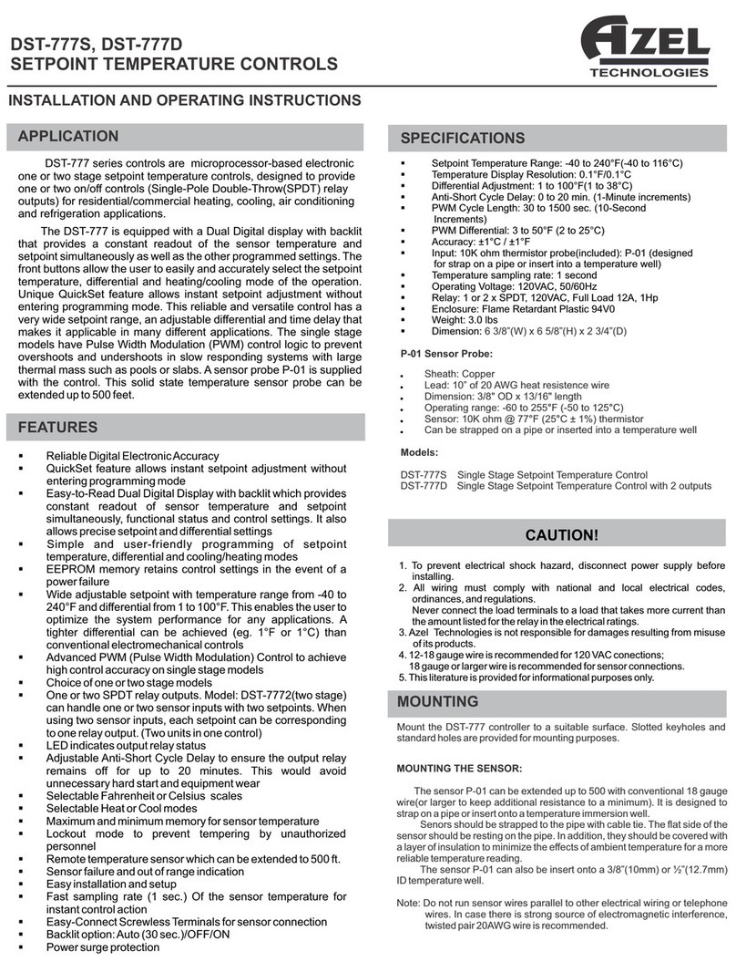
Azel DST-777 Series User manual

AZEL
TECHNOLOGIES
SETPOINT TEMPERATURE CONTROLS
DST-7772
INSTALLATION AND OPERATING INSTRUCTIONS
§Easy-to-Read Dual Digital Display with backlit which provides
constant readout of sensor temperature and setpoint
simultaneously, functional status and control settings. It also
allows precise setpoint and differential settings
§Wide adjustable setpoint with temperature range from -40 to
240°F and differential from 1 to 100°F. This enables the user to
optimize the system performance for any applications. A
tighter differential can be achieved (eg. 1°F or 1°C) than
conventional electromechanical controls
§LED indicates output relay status
FEATURES
§EEPROM memory retains control settings in the event of a
power failure
§Reliable Digital Electronic Accuracy
§Remote temperature sensor which can be extended to 500 ft.
§Adjustable Anti-Short Cycle Delay to ensure the output relay
remains off for up to 20 minutes. This would avoid
unnecessary hard start and equipment wear
§Maximum and minimum memory for sensor temperature
§Simple and user-friendly programming of setpoint
temperature, differential and cooling/heating modes
§Easy installation and setup
§Selectable Fahrenheit or Celsius scales
§Selectable Heat or Cool modes
§DST-7772can handle one or two sensor inputs with two
setpoints. When using two sensor inputs, each setpoint can
be corresponding to one relay output. (two single stage units
in one control)
§Lockout mode to prevent tempering by unauthorized
personnel
§Sensor failure and out of range indication
§Fast sampling rate (1 sec.) Of the sensor temperature for
instant control action
§Easy-Connect Screwless Terminals for sensor connection
§Backlit option: Auto (30 sec.)/OFF/ON
§Power surge protection
The DST-777 is equipped with a Dual Digital display with backlit
that provides a constant readout of the sensor temperature and
setpoint simultaneously as well as the other programmed settings. The
front buttons allow the user to easily and accurately select the setpoint
temperature, differential and heating/cooling mode of the operation.
This reliable and versatile control has a very wide setpoint range, an
adjustable differential and time delay that makes it applicable in many
different applications. The single stage models have Pulse Width
Modulation (PWM) control logic to prevent overshoots and
undershoots in slow responding systems with large thermal mass such
as pools or slabs. A sensor probe P-01 is supplied with the control. This
solid state temperature sensor probe can be extended up to 500 feet.
DST-777 series controls are microprocessor-based electronic
one or two stage setpoint temperature controls, designed to provide
one or two on/off controls (Single-Pole Double-Throw(SPDT) relay
outputs) for residential/commercial heating, cooling, air conditioning
and refrigeration applications.
APPLICATION
Mount the DST-7772 controller to a suitable surface. Slotted keyholes and
standard holes are provided for mounting purposes.
MOUNTING
SPECIFICATIONS
§Setpoint 1 Temperature Range: -40 to 240°F(-40 to 116°C)
§Setpoint 2 Temperature Range: -40 to 240°F(-40 to 116°C)
§Differential 1 Adjustment: 1 to 100°F(1 to 38°C)
§Differential 2 Adjustment: 1 to 100°F(1 to 38°C)
§Anti-Short Cycle Delay 2: 0 to 20 min. (1-Minute increments)
§Temperature Display Resolution: 0.1°F/0.1°C
§Dimension: 6 3/8”(W) x 6 5/8”(H) x 2 3/4”(D)
§Weight: 3.0 lbs
P-01 Sensor Probe:
§Operating Voltage: 120 VAC, 50/60Hz
,Sheath: Copper
,Lead: 10” of 20 AWG heat resistence wire
,Dimension: 3/8" OD x 13/16" length
,Sensor: 10K ohm @ 77 F (25 C ± 1%) thermistor° °
,Can be strapped on a pipe or inserted into a temperature well
,Operating range: -60 to 255 F (-50 to 125 C) ° °
Models:
§Enclosure: Flame Retardant Plastic 94V0
DST-7772 Two Stage Setpoint Temperature Control
§Anti-Short Cycle Delay 1: 0 to 20 min. (1-Minute increments)
§Accuracy: ±1°C / ±1°F
§Input: 10K ohm thermistor probe(included): P-01 (designed
for strap on a pipe or insert into a temperature well)
§Temperature sampling rate: 1 second
§Relay: 1 or 2 x SPDT, 120VAC, Full Load 12A, 1Hp
CAUTION!
1. To prevent electrical shock hazard, disconnect power supply before
installing.
2. All wiring must comply with national and local electrical codes,
ordinances, and regulations.
4. 12-18 gauge wire is recommended for 120 VAC conections;
5. This literature is provided for informational purposes only.
Never connect the load terminals to a load that takes more current than
the amount listed for the relay in the electrical ratings.
18 gauge or larger wire is recommended for sensor connections.
3. Azel Technologies is not responsible for damages resulting from misuse
of its products.
Note: Do not run sensor wires parallel to other electrical wiring or telephone
wires. In case there is strong source of electromagnetic interference,
twisted pair 20AWG wire is recommended.
The sensor P-01 can be extended up to 500 with conventional 18 gauge
wire(or larger to keep additional resistance to a minimum). It is designed to
strap on a pipe or insert onto a temperature immersion well.
MOUNTING THE SENSOR:
The sensor P-01 can also be insert onto a 3/8”(10mm) or ½”(12.7mm)
ID temperature well.
Senors should be strapped to the pipe with cable tie. The flat side of the
sensor should be resting on the pipe. In addition, they should be covered with
a layer of insulation to minimize the effects of ambient temperature for a more
reliable temperature reading.

!the setpoint 1 and 2 temperature alternatively if 1 sensor input is selected
Liquid Crystal Display
In normal operating mode, the upper LCD displays the current sensor 1
temperature and the lower LCD displays:
!the current senor 2 temperature if 2 sensor input is selected.
The display is also used with the Up and Down key to adjust the setpoint
temperature, differential and heating/cooling modes of the operation.
OFF - backlit is turned off.
ON - backlit is turned on.
Auto - backlit is turned on for 30 secs when any key is pressed.
LCD Blue Backlit Options: set by slide switch on the front panel
ROUGH-IN WIRING
Loosen the screws on the top and bottom of the enclosure and remove the wiring
covers by swinging them away from the base(grey color) with the edges of the
covers as pivot(see Figure 1).
The base has standard 7/8” (22mm) knockouts which accept common wiring
hardware and conduit fittings. Before removing the knockouts, check the wiring
diagrams and use the chamber with common voltages.
Figure 1
Side view
The control output will turn on when the sensor temperature falls to the setpoint
temperature minus the differential amount. The control output will turn off when the
sensor temperature reaches the setpoint temperature. For example, if setpoint =
68F, Differential = 3F, then output is on at 65F and off at 68F. In other words, when the
heating mode is chosen, the differential is below the setpoint. The relay will de-
energize as the temperature rises to the setpoint. Refer to Figure 2.
Heating Mode and Cooling Mode: set by keypad
Cooling Mode :
Heating Mode (factory setting):
The control output will turn on when the sensor temperature rises to the setpoint
temperature plus the differential amount. The control output will turn off when the
sensor temperature reaches the setpoint temperature. For example, if setpoint =
75F, Differential = 2F, then output is on at 77F and off at 75F. In other words, when
cooling mode is chosen, the differential is above the setpoint. The relay will de-
energize as the temperature falls to the setpoint.
The control output turned on means:
From the isolated SPDT relay output, “NO” are normally open contacts which close
and “NC” are normally closed contacts which open when the control output is on.
L.E.D. SYSTEM STATUS INDICATION LIGHTS:
RED light indicates that the SPDT relay output is energized.
When one sensor input is selected, the control will operate as two stage
setpoint control. The sensor (S1) controls both relay outputs. However if
Heat/Cool mode is combined (eg. Stage 1 Heat/Stage 2 Cool), it is
recommended to add a 3°F difference between the Heat setpoint and Cool
setpoint temperature. For example, if Heat setpoint is set at 68°F and Cool
setpoint should be set at 71°F.
When two sensor inputs are selected, the control will operate as two single
stage setpoint controls. Sensor (S1) controls relay 1 output and sensor (S2)
controls relay 2 output.
One or Two sensor inputs - selected by slide switch
ON (relay energized)
Setpoint OFF
(relay de-energized)
ON
OFF
Temperature
+
-
Heating
Mode
Cooling
Mode
Figure 2: Operation of relay in according to Setpoint and Differential
Settings for both Heating and Cooling Mode
The control outputs will turn on the equipment when there is a demand for
heating or cooling. When the demand is satisfied, the control outputs will turn
it off.
Control Outputs
OPERATION
Anti-Short Cycle Delay can be set to ensure the output relay remains off for up
to 20 minutes (default is 0 mins) after relay is de-energized. This is adjustable
from 0 to 20 min with 1 minute increments. In other words, this function
establishes the minimum time that the output relay remains de-energized
before the next on-cycle. The delay is activated when the control is first turned
on, but can be skipped during the display of “2SP” at startup by pressing the
“SET” key once and go to normal operating mode (Note: SET key at this stage
will not perform any other function except terminating the time delay).
Anti-Short Cycle Delay: set by keypad
When the delay is activated:
Also, in case there is a demand for heating/cooling, the red LED for relay
output will be blinking indicating that anti-cycle feature prevents relay from
energizing.
!If 1 sensor input is selected - during stage 1 delay, the Upper LCD shows
the sensor 1 temperature and “AC”(Anti-Cycle) alternatively. During stage
2 delay, the Lower LCD shows “AC”, setpoint 1, setpoint 2 alternatively.
!If 2 sensor input is selected - during stage 1 delay, the Upper LCD shows
sensor 1 temperature and “AC” alternatively. During stage 2 delay, the
Lower LCD shows sensor 2 temperature and “AC” alternatively.
Example of 2 Stage Heat Control
OFF Setpoint 1 (69 F)°
ON (Relay Output 1 at 65 )°F
ON (Relay Output 2 at 61 )°F
OFF
Temperature
+
-
Stage 2
Stage 1
Setpoint 2 (64°F)
Differential
dF1(- 4 F)°
Differential
dF2(- 3 F)°
Example of 2 Stage Cool Control
OFF
Setpoint 1 (75 F)°
ON (Relay Output 1 at 78 )°F
Temperature
+
-
Stage 1
Differential
dF1(+ 3 F)°
ON (Relay Output 2 at 81 F)°
Stage 2
OFF Setpoint 2 (79°F)
Differential
dF2(+ 2 F)°
Example of 1 Stage Heat/1 Stage Cool Control
OFF Setpoint 1 (68 F)°
ON (Relay Output 1)
ON (Relay Output 2)
Temperature
+
-
Stage 2
Cool
Stage 1
Heat
OFF Setpoint 2 (71°F)
Differential
dF1(- 2 F)°
Differential
dF2(+ 3 F)°
Minimum 3 F Gap°

SETTING THE CONTROLS
!To return to normal operating mode from the program mode, press and hold the SET key for 3 seconds. However, the system also return to normal operating
mode if no key is pressed for 30 seconds.
!During the program mode, each time SET key is pressed, the data will be saved into the EEPROM and advance to the next setting(parameter). If no change of
value is required, just press SET key once to go to the next step (parameter).
Program Mode:
General Note:
!Press and hold the Up Key or Down Key to change the value continuously (auto repeat function).
Step 5
Steps
Step 2
Step1
Step 4
Step 3
To start programming, press the SET key for 3 seconds to access the
Fahrenheit/Celsius mode. The lower LCD display will show the current status,
either F for degrees Fahrenheit or C for degrees Celsius. This annunciator will be
flashing. Then press either Up or Down key to toggle between the F or C scales.
Procedures
** Please note that this value as well as all the temperature related value are
in degree Fahrenheit as set in step 1.
Press SET key again to access the stage 1 setpoint mode. The lower LCD will
display the current setpoint (flashing) and the upper LCD will display S1
annunciator. Then press either the Up key to increase or the Down key to
decrease the setpoint to the desired setting.
Press SET key again to access the stage 1 Anti-Short Cycle time delay. The
lower LCD will display the current time delay(blinking), in minute and the upper
LCD will display AC1. Then press either the Up key to increase or the Down key
to decrease the delay to the desired setting. The increment is in 1 minute. Press
SET key again to go back to normal operating mode.
Press SET key again to access the stage 1 differential mode. The lower LCD will
display the current differential (blinking) and the upper LCD will display dF1
annunciator. Then press either the Up key to increase or the Down key to
decrease the differential to the desired setting.
Press SET key again to access the stage 1 heating or cooling mode. The upper
LCD will display the current mode, with flashing annunciator, either H1 for
heating or C1 for cooling. Then press either the Up key or the Down key to toggle
between the C1 or H1 operation.
Fahrenheit or Celsius Scale
Stage 1 Setpoint
Temperature
Description
The default value is F
Stage 1 Differential
Temperature
Stage 1 Heating or Cooling
Default setting is: 1F
Stage 1 Anti-Short Cycle
time delay
Default is: minutes0
Default setting is: 75F
Default setting is: H1
LCD Display
0
75f
S i
8f i
I f
H i
Ac i
93
Down Key
Up Key
Reset Key
Backlit Switch
2 Setpoint
Temperature for
1 Sensor Input or
Sensor 2 Temperature
for 2 Sensor Input
Sensor 1
Temperature
Fuse
Relay Output
Status
Indicator LED
SET Key
Refer to Figure 3 for
typical wiring
connections. Do not use
wire larger than 12 AWG
as jumper between
terminal blocks (eg.
“120V” and “C”)
WIRING THE CONTROL
Programming Steps
!If 2 sensor input is selected, the Upper LCD will display the current sensor 1 temperature and the Lower LCD will display current sensor 2 temperature.
When the control is powered up, the model ID - “2SP” is displayed. Then the control will run Anti-short cycle delay(if any) and goes into normal operating mode.
!If 1 sensor input is selected, the Upper LCD will display the current sensor 1 temperature and the Lower LCD will display the two setpoint temperature
alternatively.
All the slide switches (Backlit and Sensor Inputs) should be set before the control is powered up (so the desired switch settings are scanned by the
microprocessor). However if the settings on the slide switches are changed after power is supplied, press the RESET key so that the switch settings can be
updated.
POWER ON
Figure 3: Typical Wiring Diagram for DST-7772
with 120Vac Load
NC is Normally Close of SPDT switch and opens when
the relay is energized
RELAY 1/RELAY 2
S1 S1 are the input terminals for sensor probe P-01for
controlling relay 1by Stage 1 setpoint.
Terminal Representations:
COM is the neutral or ground of the line voltage
120V is the hot of the 120Vac line voltage
240V is the hot of the 240Vac line voltage
NO is Normally Open of the SPDT switch and closes
when the relay is energized
SENSOR INPUT
S2 S2 are the input terminals for sensor probe P-01for
controlling relay 2 by Stage 2 setpoint.
C is Common of the SPDT switch
S2 S2
SENSOR
INPUTS
2
1
240V COM 120V
RELAY 1
NO C NC
SENSOR INPUTS
AC INPUT
120 VAC
(HOT)
(COM) LOAD
SENSOR
PROBE
(P-01)
RELAY 2
NO C NC
LOAD
!Ensure that wires of the senor
probe are not touching each
Checkout
!Before power is applied to the
control, make sure that the
installation and wiring
connections are done
correctly. Also, ensure that
the wires connecting to COM
and 120V are not touching
each other.
S1 S1
2
2
2

Keypad Lock:
Keypad can be locked to prevent tempering by unauthorized personnel. This
is done by pressing SET , Up and Down keys at the same time for three
seconds. The word “LoC” appears on the LCD screen for 3 seconds which
indicates that the keypad is locked. Then input from the keypad is disabled.
Press SET, Up and Down keys at the same time again for another three
seconds to unlock the keypad. The word “Lof” appears on the screen for 3
seconds which indicates that the keypad is enabled.
Factory setting: unlock
Press both Up and Down keys at the same time to review the current control
settings. Then Press (or Up) key to scroll through the settings in the Down
same order as Program Mode (F/C scale, Stage 1 Setpoint, Stage 1
Differential, Stage 1 Heating/Cooling, Stage 1 Anti Cycle Time Delay, Stage
2 Setpoint, Stage 2 Differential, Stage 2 Heating/Cooling, Stage 2 Anti Cycle
Time Delay). To exit to normal mode, press one more time from Down key
the last setting (eg. AC2) or press both Up and at the same time. Down keys
In this mode, the settings cannot be changed.
Review Setting Mode:
Press RESET key if the following changes are made after the control is
powered up:
Reset:
! Slide switch settings
! Time related parameters such as anti-cycle time delay
After reset, the control will start from the beginning and run on these new
settings. Also, the maximum and minimum recorded temperature are cleared.
max
Min
T1 95f
52f
Troubleshooting Error Messages
If the upper LCD display shows flashing “Err” and
the lower LCD display shows S1(sensor 1) or
S2(sensor 2), the sensor probe is short circuited.
The corresponding relay output is de-energized.
If the upper LCD display shows flashing “LLL” and
the lower LCD display shows S1 or S2, the sensor
probe is open circuited or the sensor temperature
is out of the lower range. The corresponding relay
will be de-energized.
S i
E88
S i
Lll
S i
Hhh
If the upper LCD display shows flashing “HHH” and the
lower LCD display shows S1 or S2, the sensor
temperature is out of the upper range. The
corresponding relay will be de-energized.
Use the same procedures as above with flashing “LLL”
The second way is to obtain the P-01 resistance table from the
manufacturer. Then use a ohmmeter to measure the resistance across
the two sensor leads and compare to the temperature reading at the
sensor location.
Action: Verify if the sensor temperature is open circuited or out of the lower
range. If not, check for proper sensor operation by comparing it to a
known ambient temperature. The easiest way is to get an Azel
Technologies DS-60P digital temperature gauge which displays two P-01
sensor temperature. Connect this sensor to DS-60P and compare the
reading with the good sensor.
!If 1 sensor input is selected, the upper LCD will
display the maximum recorded sensor 1
temperature and the lower LCD will display the
minimum recorded sensor 1 temperature (figure
4).
2. Press SET key once more to exit to normal
operating mode.
Maximum and Minimum sensor temperature are
recorded in the memory. To view the max./min.
Temperature:
1. From normal operating mode, press SET key
once (eg. Just for 1 second):
!If 2 sensor input is selected, the upper LCD will
display the maximum recorded sensor 1
temperature(T1) and the lower LCD will display
t h e m a x i m u m r e c o r d e d s e n s o r 2
temperature(T2). Then press SET key to display
the minimum recorded temperature for both
sensor 1 and 2.
Max/Min Memory Mode:
Step 8
Step 6
Step 7
Steps
Step 9
Procedures
Press SET key again to access the stage 2 setpoint mode. The lower LCD will
display the current setpoint (flashing) and the upper LCD will display S2
annunciator. Then press either the Up key to increase or the Down key to
decrease the setpoint to the desired setting.
Press SET key again to access the stage 2 differential mode. The lower LCD will
display the current differential (blinking) and the upper LCD will display dF2
annunciator. Then press either the Up key to increase or the Down key to
decrease the differential to the desired setting.
Press SET key again to access the stage 2 heating or cooling mode. The upper
LCD will display the current mode, with flashing annunciator, either H2 for
heating or C2 for cooling. Then press either the Up key or the Down key to toggle
between the C2 or H2 operation.
Press SET key again to access the stage 2 Anti-Short Cycle time delay. The
lower LCD will display the current time delay(blinking), in minute and the upper
LCD will display Ac2. Then press either the Up key to increase or the Down key
to decrease the delay to the desired setting. The increment is in 1 minute. Press
SET key again to go back to normal operating mode.
Description
Stage 2 Setpoint
Temperature
Default setting is: 65F
Default setting is: H2
Stage 2 Anti-Short Cycle
time delay
Stage 2 Differential
Temperature
Default setting is: 1F
Default is: minutes0
Stage 2 Heating or Cooling
LCD Display
65f
S2
8f2
I f
H2
0
Ac2
Continue Programming Steps
Figure 4
This manual suits for next models
1
Other Azel Temperature Controllers manuals
Popular Temperature Controllers manuals by other brands

Acrel
Acrel ATE Series installation instructions

eltherm
eltherm ELTC/H-14 Operation manual

Caleffi solar
Caleffi solar iSolar 257 series Specifications

DIEL
DIEL MT200 LITE Installation and instruction manual

elsner elektronik
elsner elektronik KNX eTR 101-BA2 Installation and adjustment

JENCO
JENCO 6308CT Operation manual