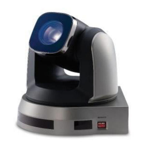
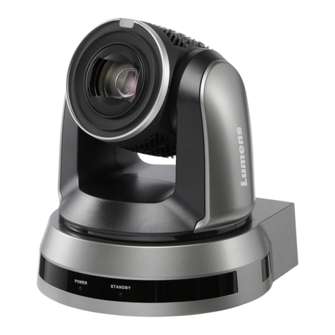
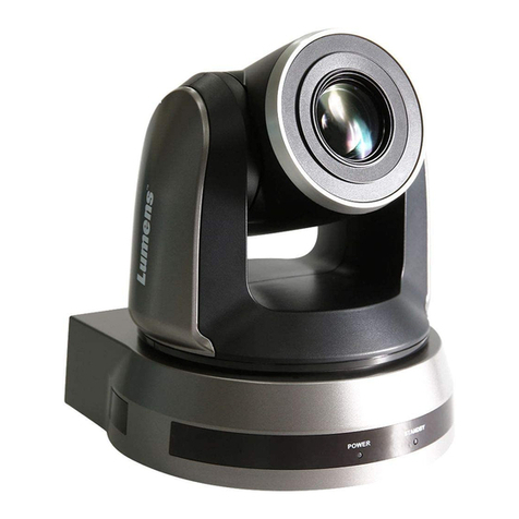
Lumens VC-A71SN User manual

1
VC-A71SN
Ultra HD camera
(4K PTZ Video Camera)
User Manual - English
To download the latest versions of the Quick Start
Guide, multilingual user manual, software, driver,
etc., please visit Lumens
https://www.MyLumens.com/support

2
Table of Contents
Chapter 1 Package Contents....................................................................3
Chapter 2 Function Introduction..............................................................4
2.1 I/ O functions Introduction.................................................................................4
2.2 Tally Lamp Function Description.......................................................................6
2.3 Description of LED indicator..............................................................................6
Chapter 3 Instruction for installation.......................................................7
3.1 Camera Size .....................................................................................................7
3.2 Preparation before installation ..........................................................................7
3.3 Instruction for installation ..................................................................................8
3.4 Connecting devices.........................................................................................13
Chapter 4 Remote Control and Setting Menu.......................................16
4.1 Functions of remote control...........................................................................16
4.2 Setting Menu...................................................................................................17
Chapter 5 Network Function Settings Description...............................21
5.1 Connecting Camera to Network......................................................................21
5.2 Web Page Function Description......................................................................23
Chapter 6 DIP Switch Setting.................................................................38
6.1 DIP SWITCH...................................................................................................38
Chapter 7 Troubleshooting.....................................................................39
Chapter 8 Safety Instructions.................................................................40
Supplier's Declaration of Conformity 47 CFR § 2.1077 Compliance Information.............41
Copyright Information...............................................................................42
3
Chapter 1 Package Contents
Camera
Quick Installation
Guide
Remote Control
Power Cord
Power Adapter
RS-422 Connector
Appearance may vary
depending on country
/ region
Metal Plate A
Metal Plate B
M3 Screws
Silver x 8 / Black x 2

4
Chapter 2 Function Introduction
2.1I/ O functions Introduction
2.1.1 Front View
NO.
Item
Function Descriptions
1.
Tally Light
Display the Tally Lamp status of the camera
2.
Camera lens
30x HD camera lens
3.
Power LED
indicator
Display the status of the camera, please refer to 2.3 Description of
LED indicator
4.
Standby LED
indicator
Display the status of the camera, please refer to 2.3 Description of
LED indicator
○
1
○
2
○
4
○
3

5
2.1.2 Back View
NO.
Item
Function Descriptions
5.
RS-232 output
RS-232 output port, at most 7 cameras can be connected in a
serial connection
6.
RS-232 input
RS-232 input port, at most 7 cameras can be connected in a
serial connection
7.
HDMI 2.0 output
HDMI 2.0 output (Audio output supported)
8.
RS-422 port
RS-422 port, at most 7 cameras can be connected in a serial
connection
9.
OUTPUT SWITCH
Adjust the resolution setting. The default is 3840 x 2160/ 59.94p
10.
Audio input
Support Line In / Mic In
11.
Network port
Network cable connection port supports routers or hubs of PoE++
(IEEE 802.3bt) with power supply
12.
DC 12V power
connector
AC power supply port
13.
IR SELECT
The remote control ID setting is only controlled after
corresponding to the Camera Select on the remote control
14.
Kensington lock hole
Safety lock slot
15.
USB 3.0 port
Connects to the USB port of the computer and provides USB
signal images
<Remark> Support up to 3840 x 2160/ 29.97p
16.
12G-SDI output
12G-SDI output (Audio output supported)
○
7
○
14
○
12
○
11
○
10
○
9
○
8
○
13
○
15
○
15
○
6
○
5

6
2.1.3 Bottom
NO.
Item
Function Descriptions
17.
Mute cooling fan
The cooling fan automatically controls its rotation speed and
performs cooling in cope with the operation temperature of the
machine
18.
Tripod lock hole
The camera is mounted on a (specification) 1/ 4” - -20 UNC tripod
19.
Rotatable foot pad
When using the metal plates of accessories, remove 4 pieces of
rotatable food pads on the bottom by rotating counterclockwise,
and then install the mental plates
2.2Tally Lamp Function Description
The Tally light function may be enabled through the RS232 command. Please refer to
VC-A71SN RS-232 command set document
2.3Description of LED indicator
Status
Power
Standby
Startup in progress
(initialization)
Green light
Orange light
In use
Green light
No indicator
In standby mode
No indicator
Orange light
○
17
○
19
○
18

7
Chapter 3 Instruction for installation
3.1Camera Size
3.1.1 Camera Front View and Side View
Length x Width x Height: 233 x 188 x 189 mm
Weight: 3.0 Kg (without mental plates)
3.1.1.1 Bottom of Camera
The camera can be mounted on a 1/ 4”-20 UNC PTZ tripod deck by using the lock holes on
the bottom for the tripod
3.2Preparation before installation
Installation and connection of HD camera requires special skills. To install by yourself,
please follow necessary steps, ensure steady and tight installation of the device, and pay
attention to your safety to avoid any accident.
189

8
3.2.1 Ensure the safety of the installation environment. Please do not install the device on
unstable ceiling or in a place where the device is in danger of falling to avoid any
accident.
3.2.2 Please check whether accessories in the box are complete or not. Please contact the
supplier for any shortage, and make sure to keep the accessories in the box intact.
3.2.3 Please choose a proper place for installation of camera in advance. Please determine
an installation place according to the following requirements
3.2.3.1 Confirm the position for the object to be captured.
3.2.3.2 Confirm whether the camera is set at a proper distance from other light sources.
3.3Instruction for installation
3.3.1 Install the camera on the desk
3.3.1.1 Precautions for installation
Please install the machine on a flat desk
Do not grab the camera head by hand when handling the device
Do not rotate the camera head by hand. Improper rotation may result in breakdown of the
camera
3.3.1.2 Installation steps
Please place the camera on a flat desktop to ensure the normal vertical and horizontal
operation of the machine and the good cooling of the fan at the bottom
3.3.2 I would like to install the camera on the ceiling
3.3.2.1 Prepare for the parts and equipment required during the installation
Accessories in the box (metal plates A, B, M3 screw silver x 8, black x 2)
Screw for locking on ceiling mounted hanger x 4
Drilling machine, screw driver, ladder

9
3.3.2.2 Metal Plate size diagram
Metal plate A - machine side
Metal plate A locking screw

10
Metal plate B - ceiling side
M3 threaded hole
M3
threaded hole
Metal plate B
locking screw
Metal plate B
locking bolt
M3
threaded hole

11
3.3.2.3 Precautions for installation
1. Before installation, please confirm the orientation of the machine relative to the object to
be captured
2. It is recommended that the machine should be set at a distance of more than 2 meter
away from the object to be captured. Please adjust for a best distance according to the
magnification of the lens
3. The machine (including metal plates) is weighed at about 4 kg. If it is to be installed on
the ceiling, please use the hanger that has obtained UL security approval to prevent the
machine from falling down.
4. Please check whether the camera is installed securely on a regular basis.
5. Please clean the cooling fan located at the bottom to ensure the good heat dissipation
effect of the machine on a regular basis.
3.3.2.4 Installation steps
1. Remove the 4 foot pads on the machine base. The foot pads are designed to be
detachable and can be removed by rotating them counterclockwise by hand.
<Remark> The removed foot pads must be kept properly for future use.
2 meter↑
Projector
Computer

12
2. Fix the metal plate A on the machine base with 4 M3 silver screws
3. Lock the metal plate B on ceiling mounted hanger
<Note>
(1) Please use the hanger that has obtained UL security approval
(2) Please reserve the hole for the connecting wires of the camera
4. Combine the metal plate A and the metal plate B
(1) Push the metal plate A up to the ceiling and then to the right to latch the metal plate B
(2) And then secure with 2 M3 silver screws and 1 M3 black screw
black
screw

13
3.3.2.5How to remove
1. Remove the connecting wires from the camera
2. Uninstall the camera together with the ceiling, loosen the three screws that fix the metal
plates A and B and push to the left to remove the machine
3. Then remove the screws on the hanger and the machine
3.4Connecting devices
3.4.1 RS-232 Connection
With RS-232 in/ out, at most 7 Lumens cameras can be connected.
RS-232 pins definition instructions

14
3.4.2 RS-422 Connection
With RS-422, at most 7 Lumens cameras can be connected.
<Note> When RS-422 connection is being used, do not use RS-232 connection.
RS-422 pins definition instructions

15
RS-422 connection instructions
1.Hold the two sides of RS-422 connector and pull out in the direction shown by the arrow
in the figure below
2.Peel off a section of copper wire (AWG Nos. 28 to 18) and insert it into the connector
hole; then use flat screw driver to fix it
3.Insert the wired RS-422 connector back to the Camera. Now the connection is
completed

16
Chapter 4 Remote Control and Setting Menu
4.1 Functions of remote control
No.
Item
Description
1.
Power
Power Switch
2.
Preset
Numeric Keys 0 - 9: Click to call the preset
Preset: Appoint an ID (0 ~ 9) to save the
current position data
Reset: Appoint an ID (0 ~ 9) to delete the
current position data
3.
Menu
Display OSD menu
4.
Pan/ Tilt
Move the lens
5.
Home-Enter
Go back to the main page/ Execute
6.
Zoom
Fast: Adjust image size
Slow: Fine-tune image size
7.
Focus
Auto: Auto focus
Manual: Enable Manual Focus
Far/ Near: Adjust the focal length in Manual
8.
Picture
Switch image effect (OFF/ Neg/ B&W)
9.
L/R Direction Set
L/R Direction / Normal
10.
Camera select
Choose Camera ID 1 ~ 3
11.
Back Light
Turn on/off back light compensation
12.
Pan/Tilt Reset
Clear the Pan/Tilt setting
13.
Freeze
Freeze the screen
14.
Mirror
Rotate the image (OFF/ Mirror/ Flip/ Rotate)
15.
Info
Status information
⓫
⓬
⓭
⓮
➊
➋
➌
➍
➎
➏
➐
➓
⓯
➑
➒

17
4.2Setting Menu
<Remark> Press [MENU] on the remote control to enter the setting menu; the bold underlined
values in the following table are defaults.
1st Level
Major Items
2nd Level
Minor Items
3rd Level
Adjustment Values
Function Descriptions
Exposure
Mode
1. Full Auto
2. Shutter Pri
3. Iris Pri
4. Manual
Exposure mode setting
Exposure Comp.
On/Off
AE Level
Exposure Comp.
Level
-5~C~5
The value can be adjusted after
Exposure Comp. is activated
Spot Light
On/Off
Spot Light
Position
X(0~6)Y(0~4)
The value can be adjusted after Spot
Light is activated
Shutter Pri
60/30 Mode
50/25 Mode
Adjustable when the Exposure
mode is set to Shutter Pri
1/10000-1/1
Iris Pri
F1.6~C~F18/ Off
Adjustable when the Exposure
mode is set to Iris Pri
Manual Gain
0-45dB
Adjustable when the Exposure
mode is set to Manual
Manual Speed
60/30 Mode
50/25 Mode
Manually set the shutter
1/10000-1/1
Manual Iris
F1.6~C~F18/ Off
Manually set the iris
Gain Limit
9-45 dB
Max. limit value of electron gain
Iris Limit
F2.2-F11
Max. limit value of iris
WDR
Off / 1/ 2/
White Balance
Mode
1. Auto
2. In Door
3. Out Door
4. One Push WB
5. ATW
6. Manual B Gain
7. Sodium Lamp
8. 3000K
9. 4300K
10. 5000K
11. 6500K
12. 8000K
Select the color temperature mode
1. 4000k ~ 7000k
2. 3200k
3. 5800k
4. 1700k ~ 10000k
5. 1700k ~ 10000k
6. Custom
7. 2800k
One Push Trigger
ENTER
One push trigger
Manual Red
0~C~128
Adjustable when the white balance
mode is set to Manual
Manual Blue
0~C~128
Adjustable when the white balance
mode is set to Manual
Picture
Picture effect
Off/ Neg/ B&W
Sharpness
0~C~14
2D NR
Off/ 1/ 2/ 3

18
1st Level
Major Items
2nd Level
Minor Items
3rd Level
Adjustment Values
Function Descriptions
3D NR
Off / LOW / Typ / Max
Image Mode
Default / Custom
The user may customize his/ her
desired image mode
Image Mode Load
ENTER
Adjustable when the Image mode is
set to Custom. After selected, the
corresponding Image mode
parameters will be read and applied
to Custom
Brightness
0~C~15
Adjustable when the Image mode is
set to Custom
Hue
0~C~15
Adjustable when the Image mode is
set to Custom
Saturation
0~C~15
Adjustable when the Image mode is
set to Custom
Gamma
0~C~3
Adjustable when the Image mode is
set to Custom
Pan Tilt Zoom
Pan/Tilt Limit
On/Off
Turn on/ off the angle limit setting
Pan Right Limit
0~170
Limit the right angle
Pan Left Limit
-170~0
Limit the left angle
Tilt UP Limit
0~90
Limit the upward angle
Tilt Down Limit
-30~0
Limit the downward angle
Pan Flip
On/Off
Activate the reverse Pan direction
Tilt Flip
On/Off
Activate the reverse Tilt direction
Preset Speed
5/ 25/ 50/ 80/ 120/ 160/ 200/
300 deg/sec
Set the PTZ rotation speed when
Preset is performed
PTZ Speed Comp
On/Off
Set the Pan/Tilt moving speed to
vary from the zoom position
D-Zoom Limit
x1~x12
Set the D-zoom limit
<Remark> 3840 x 2160 59.94/ 50
does NOT support this setting
PTZ Motion Sync
On/Off
When activated, PTZ
synchronization can be achieved by
controlling with the Presets
<Remark> Refer to the Preset speed
setting for this feature. The speed
may be adjusted automatically due to
the difference of PTZ moving range.
D-Effect
Mirror
On/ MIRROR/ Flip /
MIRROR + MIRROR
Set the mode at which the image is
mirror or flipped
Auto Focus
AF Sensitivity
LOW/ MIDDLE/ HIGH
For AF triggering speed, the higher
the speed is, the faster AF is
triggered
AF Frame
Center / Full Frame / Auto
AF frame setting, when central area
was set as AF frame, focusing will be
on the center of the screen. When
Full Frame was set as AF frame,
focusing will be calculated based on
the full screen
Zoom Tracking
Manual/ Curve Tracking/
Zoom Tracking
This function can be set in the
Manual Focus (MF) mode
Set the focus mode during lens
zooming in Manual Focus mode

19
1st Level
Major Items
2nd Level
Minor Items
3rd Level
Adjustment Values
Function Descriptions
PTZ Assist
On/Off
This function can only be enabled in
the Manual Focus (MF) mode
When PTZ Assist is enabled and
PTZ control is in operation, the focus
performs only once upon immediate
execution. The focus will not be
triggered afterward when the scene
changes
SMART AF
On/Off
Turn on this function and AF will
mainly focus on the face
Ethernet
DHCP
On/Off
Enable/Disable DHCP setting using
left and right arrow keys and press
[ENTER] to apply setting.
IP Address
192.168.100.100
Press [ENTER] to be in modify
mode; select the item to be modified
using the up and down keys, and
modify the value using the left and
right keys or the numeric keys.
Subnet mask
255.255.255.0
Press [ENTER] to be in modify
mode; select the item to be modified
using the up and down keys, and
modify the value using the left and
right keys or the numeric keys.
Gateway
192.168.100.254
Press [ENTER] to be in modify
mode; select the item to be modified
using the up and down keys, and
modify the value using the left and
right keys or the numeric keys.
Audio
Audio In
Line In/Mic In
Set Audio In
Audio Enable
On/Off
Turn on/off audio output
Audio Volume
0~C~10
Audio Volume Setting
Audio Delay
On/Off
When the audio is not synchronized
with the video, enable this function to
set the audio delay time
<Remark> Supported when NDI|HX
function setting is off
Audio Delay
Time(ms)
-1~-500ms
Set audio delay time
<Remark> Supported when NDI|HX
function setting is off
Encode Type
AAC/ G.711
Set audio encode type
<Remark> Supported when NDI|HX
function setting is off
Encode Sample
Rate
1. 48 KHz(AAC)
2. 44.1 KHz(AAC)
3. 16 KHz(AAC)
4. 16 KHz(G.711)
5. 8 KHz(G.711)
Set the encode type and sample rate
<Remark> Supported when NDI|HX
function setting is off
System
Prompt
On/Off
Turn on/off the prompt information on
the display
IR Receive
On/Off
When it is Off, the remote control will
not be able to control the camera. At
this moment, turn off and then turn
on the power to restore control of the
remote control.
Tally Lamp
On/Off
Select to enable or disable Tally
Lamp function.

20
1st Level
Major Items
2nd Level
Minor Items
3rd Level
Adjustment Values
Function Descriptions
Tally CMMD Mode
Normal/ Link
Set whether the indicator is linked
with RS232 command
Normal (Not linked): The indicator
light status and mode shall be set
separately.
When the indicator light is on and
the default mode is off, additional
command is required to set the
indicator light mode
Setting indicator light mode when
the indicator light is off will not
trigger the indicator light
Link:
When the indicator light is on, the
default mode is red light
Setting indicator light mode when
the indicator light is off will turn
on the indicator light
Language
English / 中文
Initial Position
Last MEM / 1st Preset
Select the camera lens to return to
the last operated position or the first
preset position after POWER ON
<Remark> 1st Preset = Preset 0
Control Device
Encoder / Controller
Control Device setting,
Controller: for joystick
Encoder: for tracking system
Motionless Preset
On/Off
When the function is enabled, the
screen will Freeze when Preset is
executed. Freeze will be released
after Preset is completed.
Control Port
RS-232/RS-422
Choose whether the control interface
used is RS-232 or RS-422
Protocol
VISCA / Pelco D
Baud Rate
9600/38400
Choose the transmission speed of
the control signal
VISCA Address
0~7
The Protocol set to VISCA allows the
camera ID address to be assigned.
Select 0 for automation.
PELCO D Address
1~255
The Protocol set to Pelco D allows
the camera ID address to be
assigned.
Output Mode
1. 3840x2160/59.94p
2. 3840x2160/50p
3. 3840x2160/29.97p
4. 3840x2160/25p
5. 1080p/59.94
6. 1080p/50
7. 1080p/29.97
8. 1080p/25
9. 720p/59.94
10. 720p/50
11. 1080i/59.94
12. 1080i/50
Choose the output resolution
Color Space
Standard Profile /
REC.709 / BT.2020
Set the standard for color gamut
Factory Reset
On/Off
Resume the factory default setting
Status
Display the current setting status
Other manuals for VC-A71SN
1
Table of contents
Other Lumens Digital Camera manuals

Lumens
Lumens VC-A61P User manual

Lumens
Lumens VCB20DU User manual

Lumens
Lumens VC-A50P User manual

Lumens
Lumens VC-A51S Quick start guide

Lumens
Lumens VC-TR1 User manual

Lumens
Lumens DC160 User manual

Lumens
Lumens VC-TA50 User manual

Lumens
Lumens DC-F20 User manual

Lumens
Lumens VC-B11U User manual

Lumens
Lumens VC-BR70H Quick start guide