Solar charge controller Smart-CC series User Manual
Smart-CC series intelligent solar controller, is programmable
and especially for buck mode LED solar street light system.
It includes constant current driver function, which can make
the cost of the whole system much lower.
It comes with some outstanding features, such as:
Dear Clients,
This manual gives important recommendations for installing, programming, using and so
on. Read it carefully in your own interest please.
TM
Thanks for selecting the Smart -CC series solar controller. Please take the time to read this user manual, this will help you to take
advantage of controller’s new features.
1.Description of Function
Can output constant power, output power can be set.
5 stages time and dimming can be adjusted
Can read parameters and running status
Automatic Liquid/GEL)
Suitable for Gel, Liquid, AGM and Lithium battery
Auto sleeping during transportation
Low temperature charging protection
When BMS power off because of LVD, it can activate
the system automatically
Charging target and recovery voltage can be
set
Day/Night threshold can adjust automatically
Remote Unit to configure, with LCD display
IP67, Strong and durable aluminum case
Full automatic electronic protect function
temperature compensation(
(Lithium)
(Lithium)
0℃ Charging Protection(Lithium)
2.Safety instructions and waiver of liability
2.1 Safety
①The solar charge controller may only be used in PV
systems in accordance with this user manual and the
specifications of other modules manufacturers. No
energy source other than a solar generator may be
connected to the solar charge controller.
②Batteries store a large amount of energy, never short
circuit a battery under all circumstances. We strongly
recommend connecting a fuse directly to the battery to
protect any short circuit at the battery wiring.
2.2
③Batteries can produce flammable gases. Avoid making
sparks, using fire or any naked flame. Make sure that the
battery room is ventilated.
④Avoid touching or short circuiting wires or terminals.
Be aware that the voltages on special terminals or wires
can be as much as twice the battery voltage. Use isolated
tools, stand on dry ground, and keep your hands dry.
⑤Keep children away from batteries and the charge
controller.
Liability Exclusion
The manufacturer shall not be liable for damages,
especially on the battery, caused by use other than as
intended or as mentioned in this manual or if the
recommendations of the battery manufacturer are
neglected. The manufacturer shall not be liable if there
has been service or repair carried out by any
unauthorized person, unusual use, wrong installation, or
bad system design.
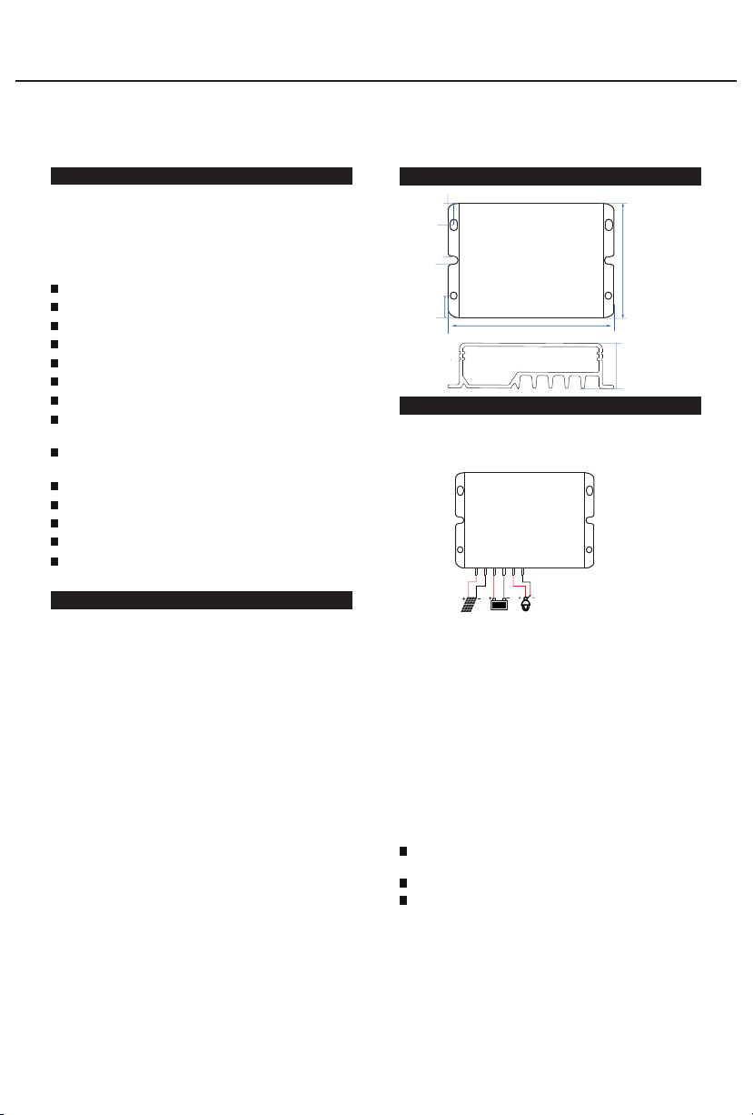
3.Dimensions
4.Installation
Page 1 of 5 pages
The following diagrams provide an overview of the
connections and the proper order.
1.Follow the chart, connect the load (positive pole and
negative pole) with the corresponding brown and blue
cables firstly, then seal them with tape.
2.Connect battery positive pole and negative pole to the
corresponding red and black cables, the load will be on
after 8s;
3.Connect the panel positive pole and negative pole to
the corresponding red and black cables, the load will be
off after 4s, and the controller begins to charge.
4.Confirm the LED display status: If the red LED is off
and the green LED flashes or constantly light, it is
normal; else it means fault, please refer to the 9.2 Faults
and Alarms to identify the reason.
Make sure the length between battery and controller is as
short as possible.
Recommended minimum wire size: 2.5mm²;
For easy installation and testing, in the first 5minutes,
charging and discharging conversion requires only 8s.
After 5 minutes, charging and discharging conversion
takes time of 5 minutes.
4.1 Connection sequence
4.2 Transportation mode(Load off)
4.2.1 Open circuit protection
If the controller is only connected with the battery,
but not connected with solar and load, the controller
will enter transportation mode after 5 minutes.
76.4
52
2. 5
10
10
4
20.7
④
③
⑥
⑤②
①


