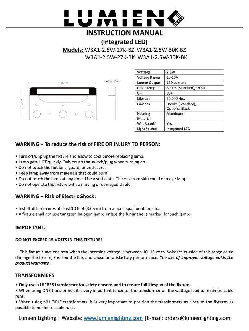
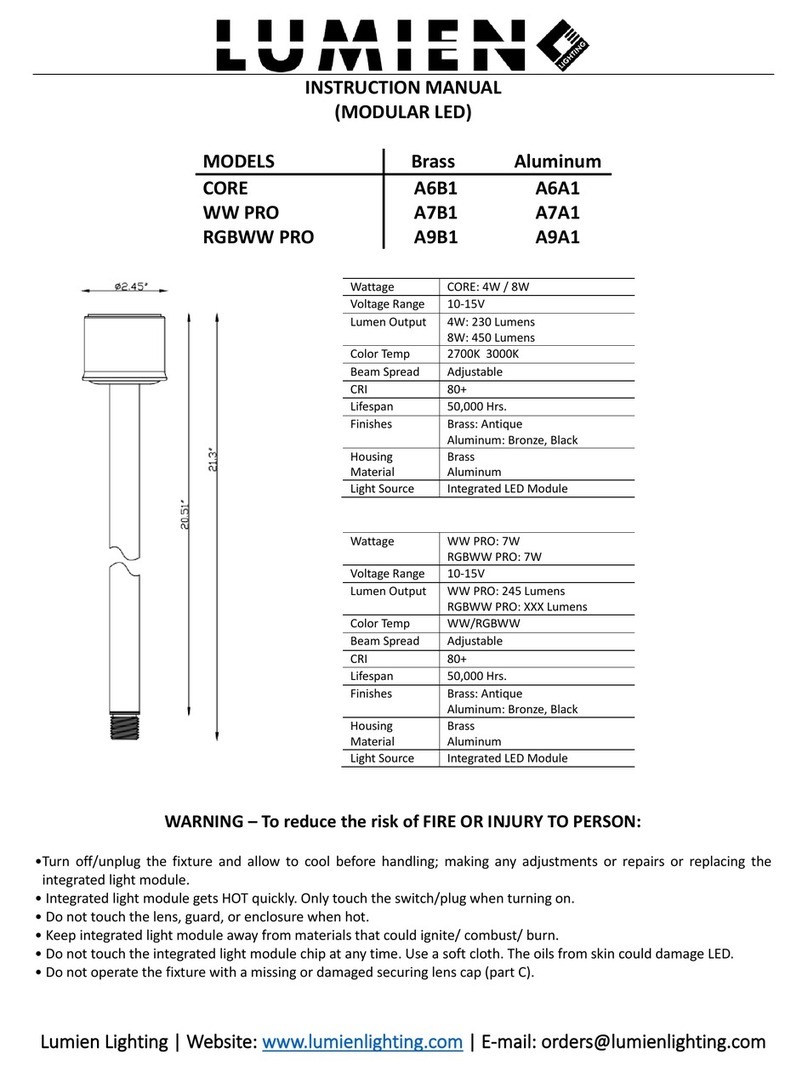
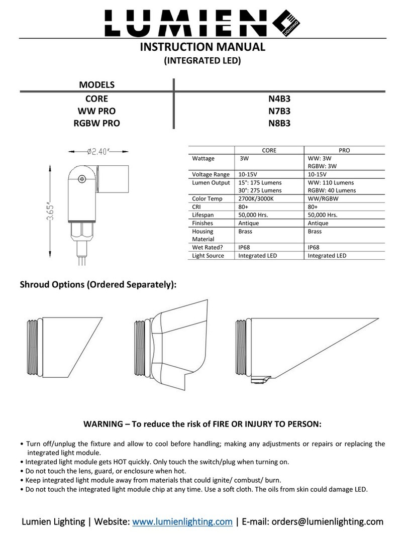
LUMIEN N4B1 User manual

Lumien Lighting | Website: www.lumienlighting.com | E-mail: orders@lumienlighting.com
INSTRUCTION MANUAL
(MODULAR LED)
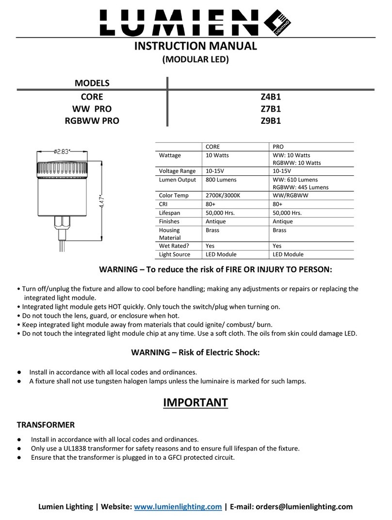
MODELS
CORE
N4B1
WW PRO
N7B1
RGBW PRO
N8B1
Wattage
CORE: 1.5W / 2.5W
PRO WW: 2.5W
PRO RGBW: 2.5W
Voltage Range
10-15V
10-15V
Lumen Output
1.5W: 125 Lumens
2.5W: 205 Lumens
PRO WW: 200 Lumens
PRO RGBW: 87 Lumens
Color Temp
2700K/3000K
WW/RGBW
CRI
80+
80+
Lifespan
50,000 Hrs.
50,000 Hrs.
Finishes
Antique
Antique
Housing Material
Brass
Brass
Wet Rated?
IP68
IP68
Light Source
Integrated LED
Integrated LED
WARNING –To reduce the risk of FIRE OR INJURY TO PERSON:
• Turn off/unplug the fixture and allow to cool before handling; making any adjustments or repairs or replacing the
integrated light module.
• Integrated light module gets HOT quickly. Only touch the switch/plug when turning on.
• Do not touch the lens, guard, or enclosure when hot.
• Keep integrated light module away from materials that could ignite/ combust/ burn.
• Do not touch the integrated light module chip at any time. Use a soft cloth. The oils from skin could damage LED.
WARNING –Risk of Electric Shock:
●Install in accordance with all local codes and ordinances.
●A fixture shall not use tungsten halogen lamps unless the luminaire is marked for such lamps.
IMPORTANT
TRANSFORMER
●Install in accordance with all local codes and ordinances.
●Only use a UL1838 transformer for safety reasons and to ensure full lifespan of the fixture.
●Ensure that the transformer is plugged in to a GFCI protected circuit.
FIXTURE
(DO NOT EXCEED 15 VOLTS INPUT)
•Install in accordance with all local codes and ordinances.
•This fixture functions best when the incoming voltage is between 10–15 volts. Voltages outside of this range
could damage the fixture, shorten the life, and cause unsatisfactory performance. The use of improper voltage
•voids the product warranty.

Lumien Lighting | Website: www.lumienlighting.com | E-mail: orders@lumienlighting.com
LOW VOLTAGE CABLE
•Install in accordance with all local codes and ordinances.
•Be protected by routing near the luminaire, or next to a building structure such as a house or deck.
•Not be buried except for a maximum of 6 inches (15.2 cm) to connect to the main low voltage cable.
•Have the length cut off so that it is connected to a connector within 6 inches (15.2 cm) from a building structure,
a luminaire, or fitting.
It is not recommended to use Quick Clip style connectors because they are not waterproof and can rot creating resistance
and shorts. Only use outdoor rated waterproof wire connectors. Install in accordance with all local codes and ordinances.
LED LIFE
•For maximum light output, adjust lighting circuits to provide between 10-15 volts.
•Voltage can be regulated by adjusting circuit load/run.
•To determine circuit voltage, use a digital voltmeter at the fixture.
INSTALLATION
Recessed Installation
A –Recessed Cap B –O-Ring C –LED Module D- O-Ring E - Female Connector F- Lock Nut
G -Silicone Sleeve H- Assembled Fixture I-PVC Pipe J-Waterproof Wire Nuts
Installation Procedure
•Assemble A,B,C,D,E,F,G into fixture according to the diagram (H).
•Choose the appropriate PVC pipe (I) (Sold Separately) and bury it in the wall.
•Pull the wire out of the PVC pipe (I) and connect the fixture to the main line with waterproof wire nuts (not
included).
•Insert the fixture (H), into the PVC Pipe.
•For PRO modules, follow the instruction on our LumienPRO’s remote control.

Lumien Lighting | Website: www.lumienlighting.com | E-mail: orders@lumienlighting.com
Cap Options - Choose to replace A(LAB-110) with the caps below.
Hanging Installation
A1- Lock Nut A2- Ring Mount B - Female Connector C- O-Ring D- LED Module E- O-Ring
F- Glass Shroud G- Assembled Fixture H-Stainless Steel Wire I- Waterproof Wire Nuts

Lumien Lighting | Website: www.lumienlighting.com | E-mail: orders@lumienlighting.com
Installation Procedure:
•Before installation, unscrew the lock nut (A1) from the LED module (D) counterclockwise.
•Assemble A2,B,C,D,E,F,into fixture according to the diagram (G).
•Fixture should always have the light source facing downward. Using the desired metal cable (H), loop the cable
around the top eyelet and secure as shown below.
•Connect fixture wires to main low voltage wire using outdoor rated waterproof (I) wire nuts.
•For PRO modules, follow the instruction on our LumienPRO’s remote control.
Optional Shades
360°Glass Bollard Installation
A1- Lock Nut A2- Quick Connect Spike B- Female Connector C- O-Ring D- LED Module E- O-Ring F- 360°Glass Bollard
G –Assembled 360°Glass Bollard Fixture H- Quick Connect Riser I- Waterproof Wire Nuts

Lumien Lighting | Website: www.lumienlighting.com | E-mail: orders@lumienlighting.com
Installation Procedure:
•Before installation, unscrew the lock nut (A1) counterclockwise from the LED module (D), and remove the female
wire (B) and O-Ring (C).
•Assemble D, E, F into fixture according to the diagram (G).
•Pass the female cable (B) out of the quick-connect plastic spike (A2), put on the O-Ring (C), and then connect
the assembled 360°glass bollard fixture (G) to the quick-connect plastic spike.
•Prepare a hole in the installation location. Make sure the hole is not larger than the ground spike.
•Install the fixture in the ground and connect fixture wires to main low voltage wire using outdoor rated
waterproof wire nuts.
•If the assembled fixture needs to be heightened, you can choose different lengths of quick-connect extension
rods (H).
•For PRO modules, follow the instruction on our LumienPRO’s remote control.
90°Glass Bollard Installation
A1- Lock Nut A2- Quick Connect Spike B - Female Connector C- O-Ring D- LED Module
E- O-Ring F- 90°Glass Bollard Component G- Assembled Single-Sided 90°Opening Fixture
H- hexagonal screw I -S ingle-Sided 90°Opening Cover J- Quick Connect Riser K- Waterproof Wire Nuts
Installation Procedure:
•Before installation, unscrew the lock nut (A1) counterclockwise from the LED module (D), and remove the
female wire (B) and O-Ring (C).
•Assemble D, E, F into fixture according to the diagram (G).
•Pass the female wire (B) out of the quick-connect plastic spike (A2), put on the O-Ring (C), and then connect
the one-sided 90°assembled fixture (G) with the quick-connect plastic spike (A2) by turning the fixture
clockwise.
•Insert the single-Sided 90°Opening Cover (I) into Assembled Single-Sided 90°Opening Fixture (g), adjust it to
the light-emitting direction you want, and fasten it with the hexagonal screw (H)
•Prepare a hole in the installation location. Make sure the hole is not larger than the ground spike.
•Install the fixture in the ground and connect fixture wires to main low voltage wire using outdoor rated
waterproof wire nuts.
•If the assembled fixture needs to be heightened, you can choose different lengths of quick-connect extension
rods (J).
•For PRO modules, follow the instruction on our LumienPRO’s remote control.

Lumien Lighting | Website: www.lumienlighting.com | E-mail: orders@lumienlighting.com
.
Optional Caps
LIMITED WARRANTY
WHAT IS COVERED
The manufacturer warrants this lighting fixture to be free from defects in materials and workmanship from date of
purchase for a period of ten (10) years for Aluminum and Lifetime for Brass. This warranty applies only to the original
consumer purchaser and only to products used in normal use and service. If this product is found to be defective, the
manufacturer’s only obligation, and your exclusive remedy, is the repair or replacement of the product at the
manufacturer’s discretion, provided that the product has not been damaged through misuse, abuse, accident,
modification, alteration, neglect, or mishandling.
WHAT IS NOT COVERED
This warranty shall not apply to any product that is found to have been improperly installed, set-up, or used in any way
not in accordance with the instructions supplied with the product. This warranty shall not apply to a failure of the product
because of an accident, misuse, abuse, negligence, alteration, faulty installation, or any other failure not relating to faulty
material or workmanship. This warranty shall not apply to the finish on any portion of the product, such as surface and/or
weathering, finish defects or fusing of the metals are considered normal wear and tear due to proximity to harsh
environments; this includes but is not limited to coastal areas, ground water (minerals and impurities) and chemicals used
in the landscape. The manufacturer does notwarrant and especially disclaims any warranty,whether expressed or implied,
of fitness for a purpose, other than the warranty contained herein. The manufacturer specifically disclaims any liability
and shall not be liable for any consequential or incidental loss or damage, including but not limited to any labor/expense
costs involved in the replacement or repair of said product.
This manual suits for next models
2
Table of contents
Other LUMIEN Outdoor Light manuals

LUMIEN
LUMIEN D3A1-12W-27K-BZ User manual

LUMIEN
LUMIEN N4B3 User manual

LUMIEN
LUMIEN A3A1-5W-30K-BZ User manual
LUMIEN
LUMIEN CORE D5A1 User manual

LUMIEN
LUMIEN R5A1-10W-27K-BZ User manual

LUMIEN
LUMIEN CORE D6B1 User manual

LUMIEN
LUMIEN A5A1 User manual
LUMIEN
LUMIEN CORE A6B1 User manual

LUMIEN
LUMIEN A3A3 User manual
LUMIEN
LUMIEN CORE User manual
Popular Outdoor Light manuals by other brands

Quoizel
Quoizel WKF9011EK Assembly instruction sheet

LIGMAN
LIGMAN OD-50001 installation manual

REV Ritter
REV Ritter FLEXLIGHT EML262-S Assembly and operating instructions

LUG
LUG TRAFFIK R LED installation instructions

WE-EF
WE-EF RLS400 Series Installation and maintenance instructions

Malibu Boats
Malibu Boats CL4 instructions