7
luminancebrands.com
Please contact 1-800-777-4440 for further assistance
Model No.: RCK55
Receiver Installation
If you feel that you do not have enough electrical
wiring knowledge or experience, have your fan
installed by a licensed electrician.
To avoid possible electrical shock, be sure
electricity is turned off at the main fuse box or
circuit breaker panel before wiring.
NOTE: If you are not sure if the outlet box is
grounded, contact a licensed electrician for
advice, as it must be grounded for safe operation.
WARNING
!
To reduce the risk of electrical shock, disconnect
the electrical supply circuit before installing the
fan, light kit or receiver.
CAUTION
!
Disconnect Electrical Power to the Branch Circuit at
the Circuit Breaker Panel or Main Fuse Box before
attempting to Wire the Ceiling Fan.
Turning off wall switch is not sufficient.
To avoid possible electrical shock, be sure
electricity is turned off at the main fuse
box or circuit breaker panel before wiring.
All wiring must be in accordance with National
and Local codes and the ceiling fan must be
properly grounded as a precaution against
possible electrical shock.
WARNING
!
This product is designed to use only those
parts supplied with this product and/or any
accessories designated specifically for use
with this product by Luminance Brands.
Substitution of parts or accessories not
designated for use with this product by
Luminance Brands could result in personal
injury or property damage.
WARNING
!
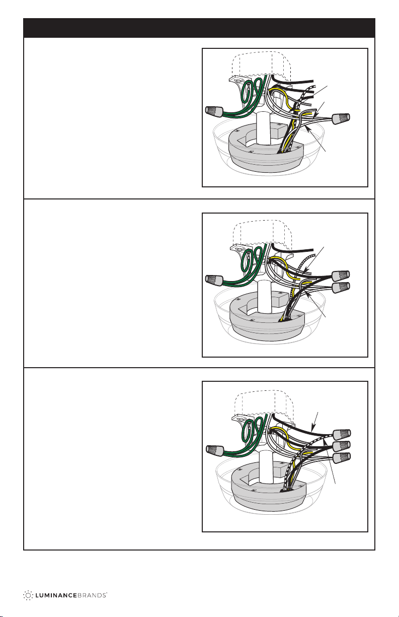
SUPPLY GROUND
WIRE
(GREEN OR BARE)
HANGER BALL
GROUND WIRE
(GREEN)
HANGER BRACKET
GROUND WIRE
(GREEN)
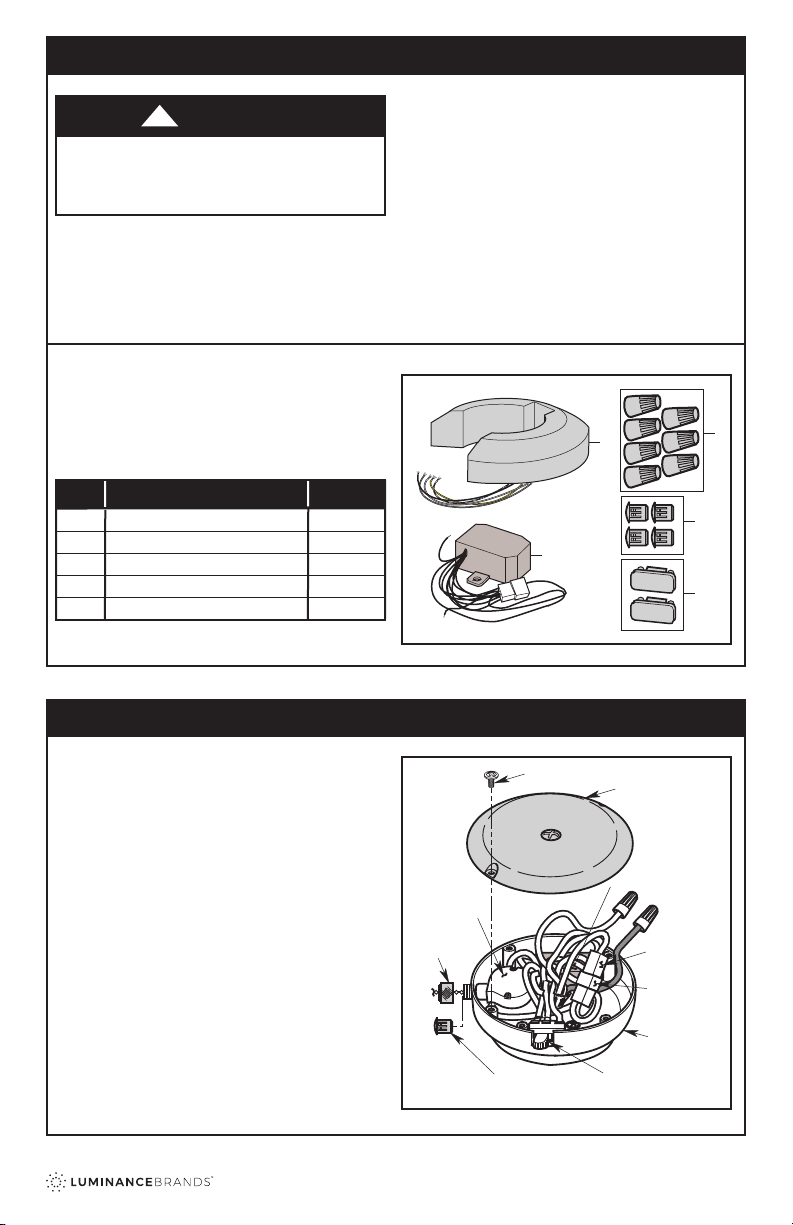
RECEIVER
NOTCH
CEILING
COVER
OPEN SIDE OF
HANGER
BRACKET
SIDE OF
HANGER
BRACKET
Figure 14
3.1
1. Pull the Ceiling Fan Downrod Wires and the
Supply Wires through the open side of the Hanger
Bracket.
2. Position the RCK55 Receiver in the Ceiling Cover
so that the at side of the Receiver faces up. Align
the Notch in the Receiver with the Side of the
Hanger Bracket. Also ensure the Receiver wires
align with the open side of the Hanger Bracket.
(Figure 14).
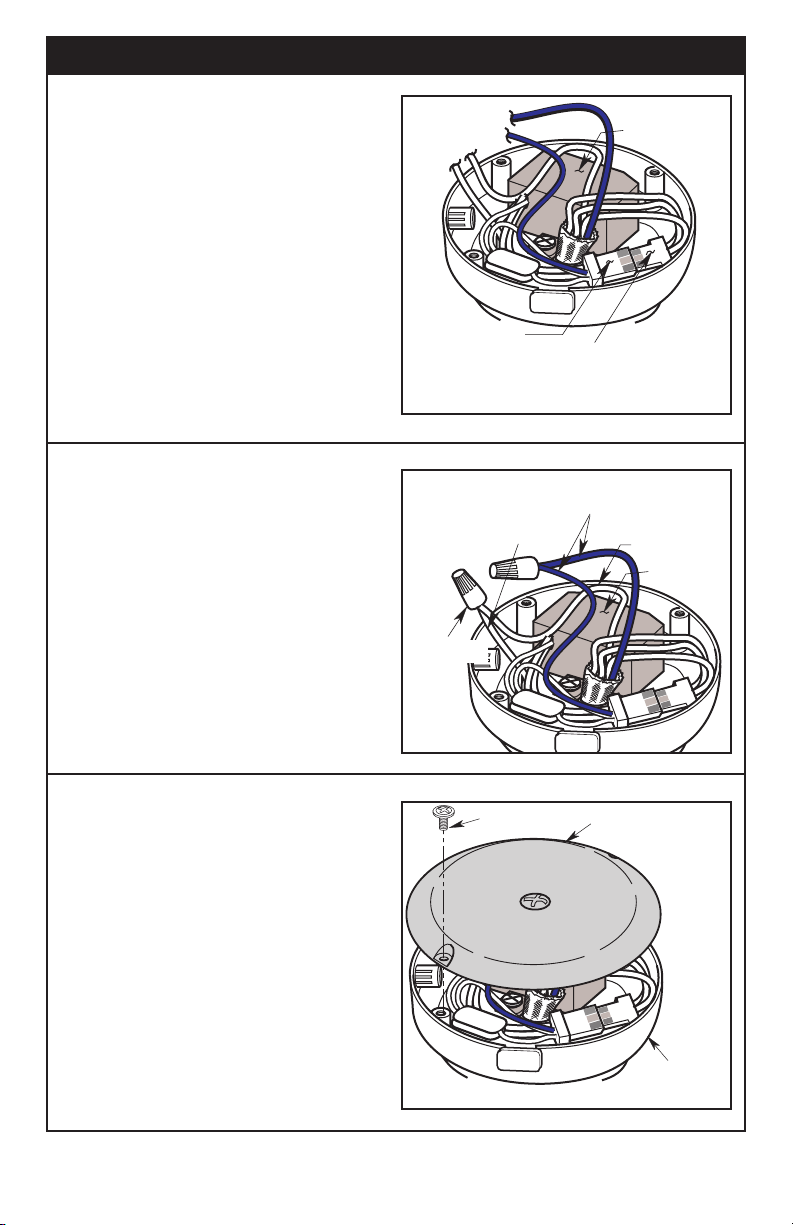
Figure 15
3.2
NOTE: Make all wiring connections using the wire
connectors supplied in the receiver parts bag.
Make sure that all connections are tight, including
ground, and that no bare wire is visible at the wire
connectors, except for the supply circuit ground wire.
3. Connect the Hanger Ball Green Ground Wire and
the Hanger Bracket Green Ground Wire to the
Supply Ground Conductor (this may be a bare wire
or wire with Green Colored insulation).
4. Securely connect Wires with Wire Connector
(supplied in parts bag) (Figure 15).
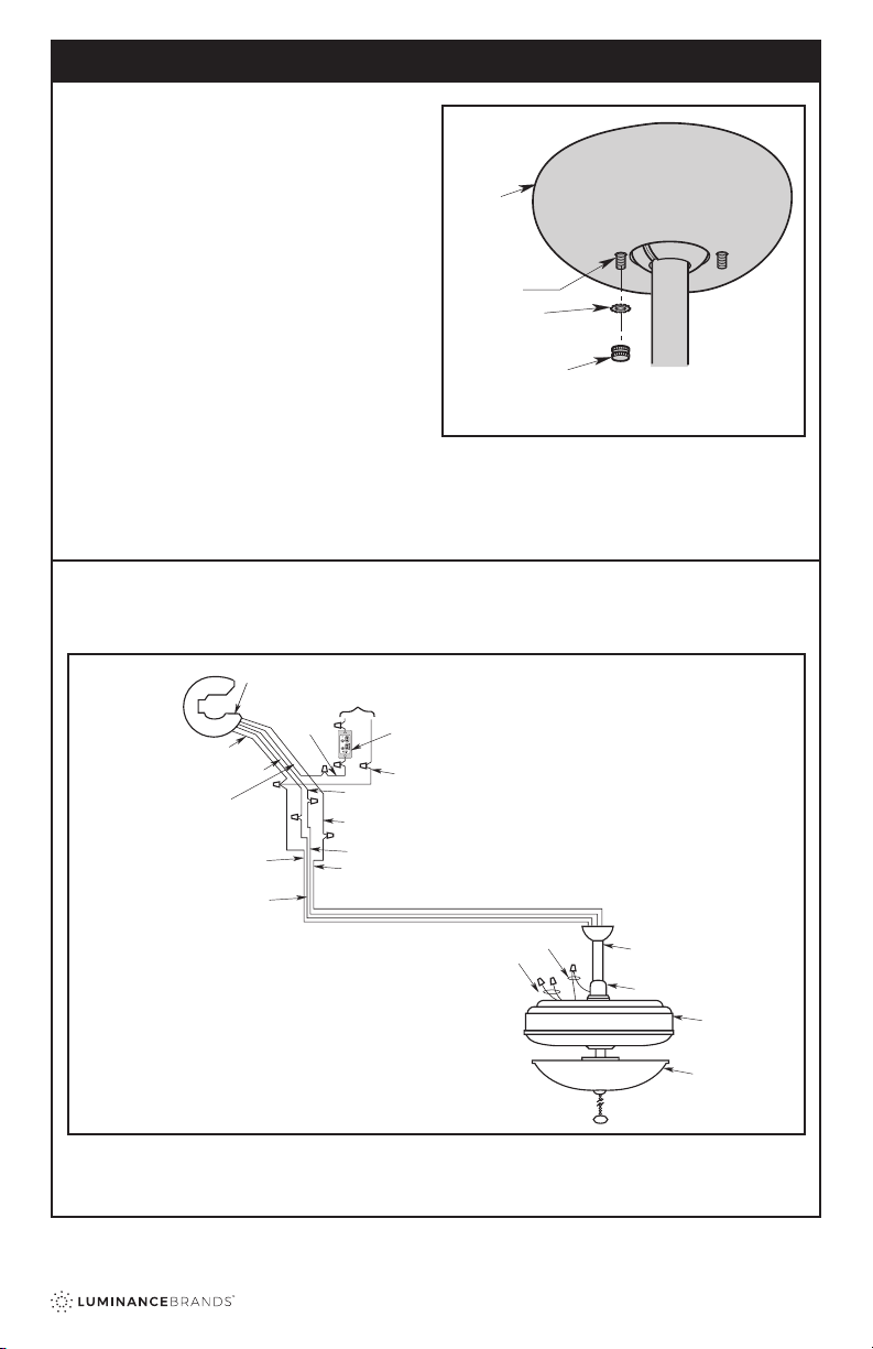
Assemble your Ceiling Fan (including the fan blades),
install the Hanger Bracket, and then hang the Fan in
accordance with the instructions in the Ceiling Fan
Owner’s Manual. Wire the Ceiling Fan and Receiver
and complete the installation in accordance with the
following: