READ AND SAVE THESE INSTRUCTIONS
TO REDUCE THE RISK OF FIRE, ELECTRICAL
SHOCK, OR INJURY TO PERSONS, OBSERVE
THE FOLLOWING:
a. Use this unit only in a manner intended by
the manufacturer. If you have questions,
contact the manufacturer.
b. Before servicing or cleaning unit, switch
power off at service panel and lock
service panel disconnecting means to
prevent power from being switched on
accidentally. When the service discon-
necting means cannot be locked, securely
fasten a warning device, such as a tag, to
the service panel.
WARNING
!
Part No. F40BP74990001 Form No. BP7499-1
Revision: 03052021 Printed in China 03/2021
Ceiling Fan Wall Control Owner’s Manual
Safety Instructions
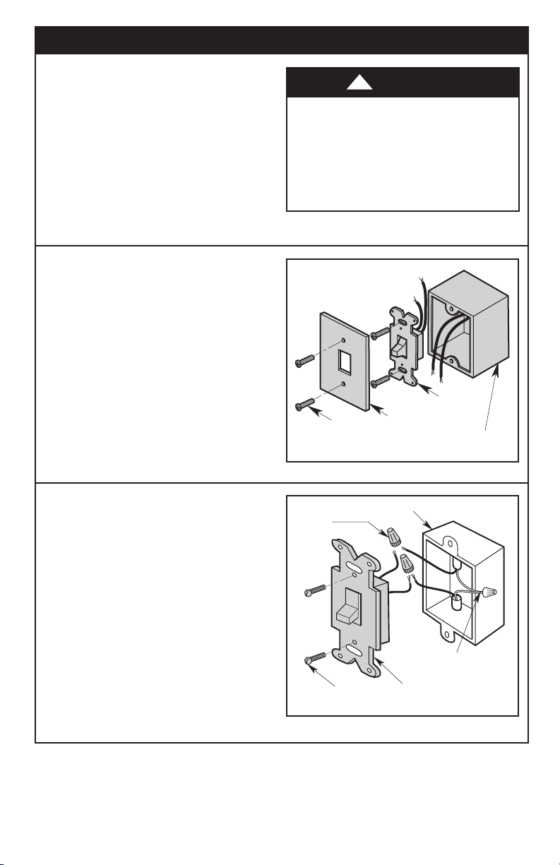
3. Do not mount the Fan Wall Control near heat
producing equipment.
4. All wiring must be in accordance with the
National Electrical Code “ANSI/NFPA
70-2017” and Local Electrical Codes. Use the
National Electrical Code if Local Codes do
not exist. If you feel you do not have enough
electrical wiring knowledge or experience,
have your Fan Control installed by a licensed
electrician. Electrical installation should be
made or approved by a licensed electrician.
5. Use of this control with some ceiling fans
could result in fire, shock and serious
personal injury. Use this speed control only
with ceiling fans that are suitable for use with
solid-state controls.
6. This product is designed for use with only those
ceiling fans designated specifically for use with
this product by Luminance Brands. Substitution
of parts or accessories not designated for use
with this product by Luminance Brands could
result in personal injury or property damage.
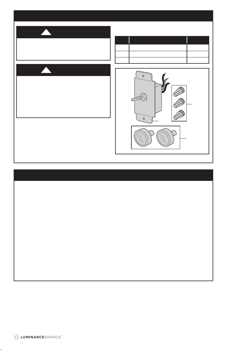
Model Number: SW93
• DUAL FAN CONTROL
• Maximum: 3.0 AMP, 120 VAC, 60 HZ, Single-Pole
• 3-Speed Fan Motor Control
Model Number: SW95
• SINGLE FAN CONTROL
• Maximum: 1.25 AMP, 120 VAC, 60 HZ, Single-Pole
• 4-Speed Fan Motor Control
Model Number: SW96
• 3-4 FAN CONTROL
• Maximum: 5.0 AMP, 120 VAC, 60 HZ, Single-Pole
• 4-Speed Fan Motor Control
1. Read your Owner’s Manual carefully and keep it
for future reference.
2. Make certain no bare wires are exposed outside
the wire connectors.
ACCESSORY