Bastl Instruments POPCORN v1.1 User manual

last update: 19. 7. 2018
POPCORN v1.1 - Assembly Guide
bastl-instruments.com
INTRODUCTION
This guide is for building Popcorn module from Bastl Instruments. It is good to have basic soldering
skills and to be able to identify electronic components before starting this kit. However if you have
never soldered before, check out this tutorial first .
1
The Popcorn kit consists of two boards. All the parts comes in three bags separated for Top board,
Bottom board and Assembly parts. See Bill of Materials (BOM) for detailed list. We even included
some of the best quality solder to help you solder everything faster and better.
1 http://www.instructables.com/id/How-to-solder/
1

BILL OF MATERIALS
POPCORN v1.1
TOP BOARD
qty
value
part
6
220R
R-EU_0204/5
9
1k
R-EU_0204/5
9
17mm
long small button
6
PJ-301BMB
jack connector
9
green
LED 3 mm
6
bipolar R/G
LED 3 mm
8
B100K 25mm
linear potentiometer
2
B100K 25mm
linear potentiometer - central detent
1
2x4 pin
Male pinheader
1
19 pin
Male pinheader
4
6 pin
Male pinheader
BOTTOM BOARD
1
220R
R-EU_0204/5
1
1k
R-EU_0204/5
2

1
10k
R-EU_0204/5
8
100k
R-EU_0204/5
1
33k
R-EU_0204/5
1
47k
R-EU_0204/5
1
330k
R-EU_0204/5
1
4M7
R-EU_0207/5
2
1N4007
DIODE-D-7.5
17
100nF
ceramic capacitor
4
10uF
electrolytic capacitor
3
2N3904
transistor
1
7805
voltage regulator
1
L79L05
voltage regulator
1
16MHz
resonator
2
100mA
fuse
1
ATMEGA328-PU-ND
4
74HC595
IC in foam
3
CD4051BE
IC in foam
1
MCP6002
IC in foam
1
MCP4921
IC in foam
1
TL072
IC in foam
3
8 pin DIL
DIL socket - in foam
7
16 pin DIL
DIL socket - in foam
1
28 pin DIL
DIL socket - in foam
2
40 pin
Female pinheader
1
2x4 pin
Double female pinheader
1
6 pin
Male pinheader
1
8 pin
Male pinheader
3
2x5 pin
Double male pinheader
ASSEMBLY
1
M3 x 11mm
spacer nut x nut
1
M3 x 11,5mm
spacer screw x nut
3
M3 x 6mm_Imbus
screw
1
M3
nut
4
M3 x 8mm_cross
panel screw + washers
6
jack washers
6
jack nuts
1
allen key
1
bottom
PCB
1
top
PCB
1
power cable 10-10pin
1
power cable 10-16pin
1
front panel / w DIY sign
3

BEFORE STARTING THE KIT...
Before starting this kit, prepare the following tools:
● Soldering iron
● Multi-meter
● Flush cutters
● Smaller pliers
● n2. hex screwdriver or allen key (enclosed with kit)
● Phillips screwdriver
● Wrench No. 8
● Protective eyewear
● Isopropyl alcohol + smaller and clean brush (optional)
We suggest that you work in a clean and a well lit and ventilated environment to avoid accidents or
losing any of the small components. Also briefly go through this guide and make sure that you
understand all the steps before you start soldering.
When you are done with soldering, you would probably like to calibrate your Popcorn. It is pretty
simple. Please check the info about firmware v1.1 and calibration guide here .
2
BOTTOM BOARD
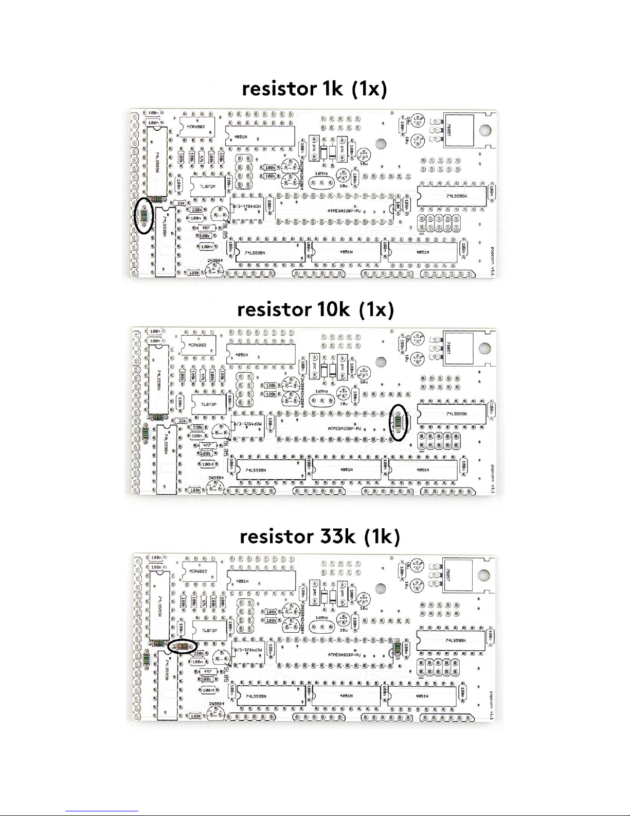
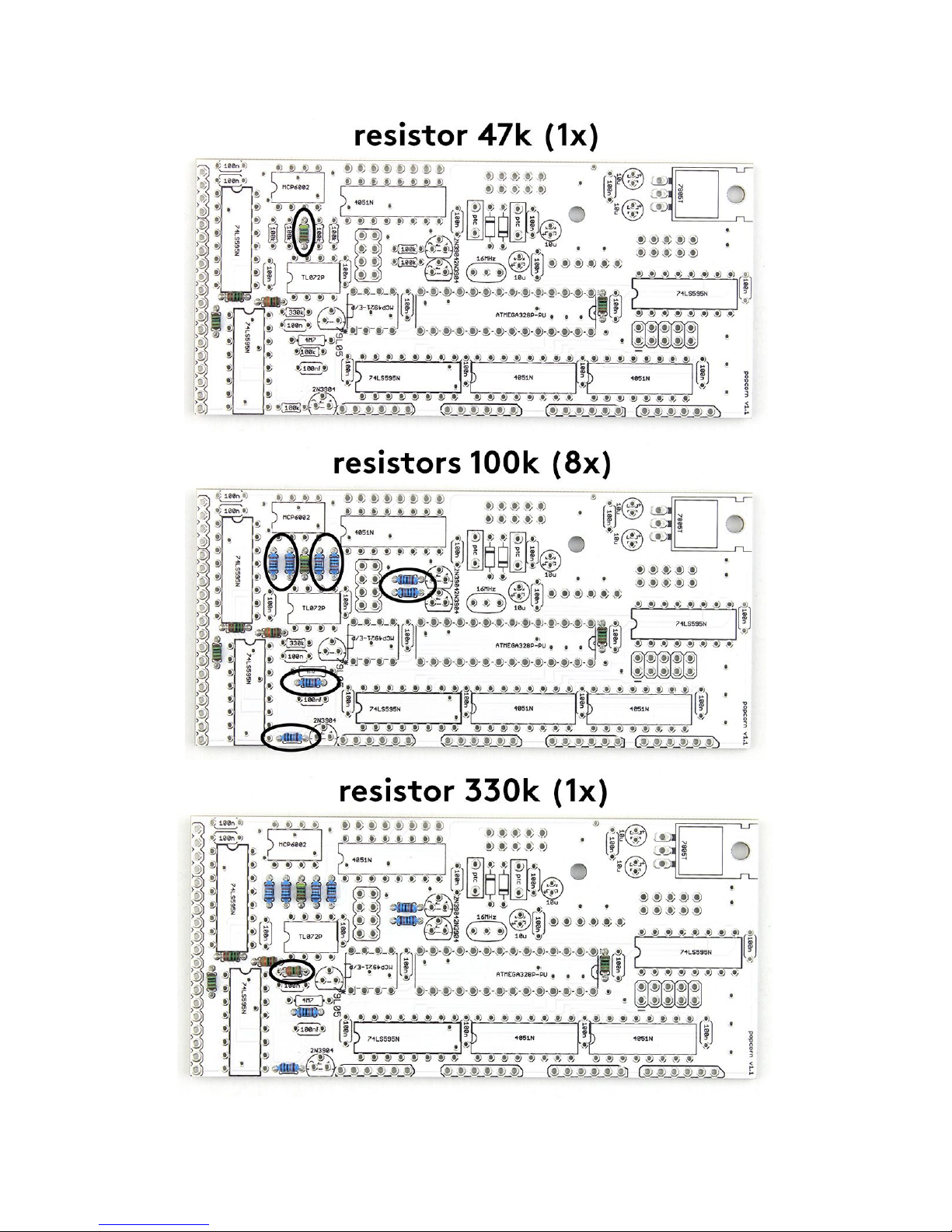
RESISTORS
Start with the bottom board parts. First of all, take your time and check the values of all resistors
using a multimeter (or you can check the color codes if you are seasoned enough):
3
-220R (1x), 1k (1x), 10k (1x), 33k (1x), 47k (1x), 100k (8x), 330k (1x), 4M7 (1x).
Then solder them on the bottom PCB and snip the leads close to the PCB (be sure to make this step
on all remaining leads in the course of this guide).
2 http://www.bastl-instruments.com/wp-content/uploads/2018/06/popcorn-v1.1-update.pdf
3 https://learn.sparkfun.com/tutorials/how-to-use-a-multimeter/measuring-resistance
4
5
6
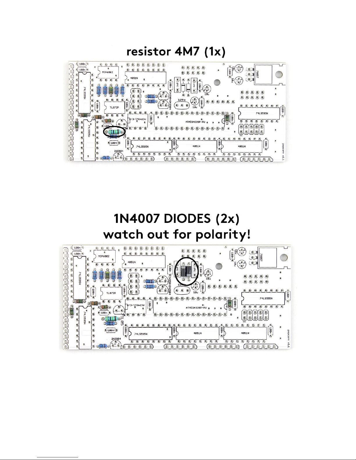
DIODES
Solder also the diodes (1N4007 - 2x). Be careful, diodes are polarized! Make sure that the marking
ring on the diode body matches the marking on the circuit board. Check the photo below.
7
MALE HEADERS
Solder the male pinheaders now (1x 6 pins, 1x 8 pins and 3x double 5x pins). Be careful to solder
them straight. You may first solder just one of the pin, take the board in your hand and re-heat that pin
while pressing down on the header to align it (be careful, you don’t want to touch the pin you are
heating up). Wait for it to cool and solder the rest of the pins.
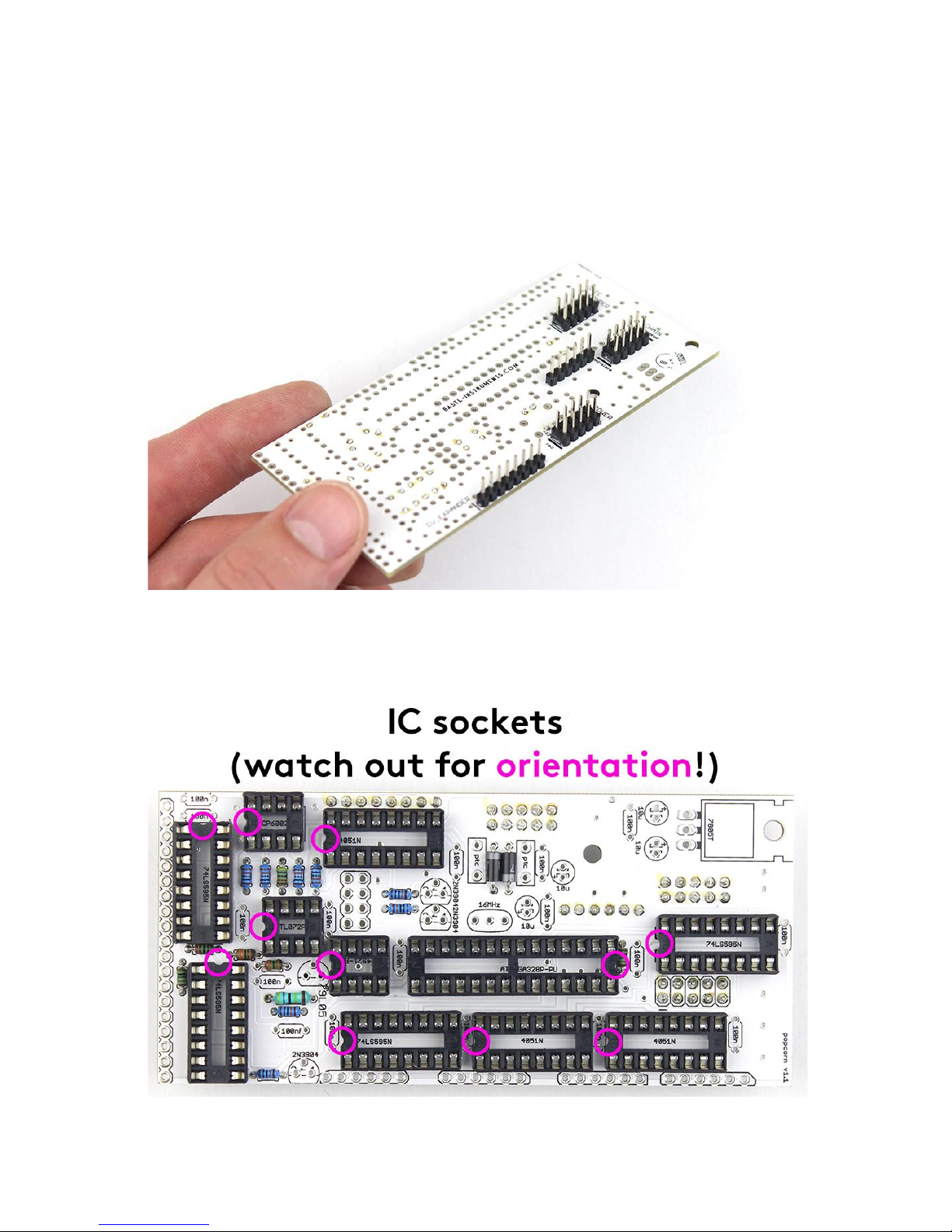
IC SOCKETS
Solder all the IC sockets (3x 8 pin, 7x 16 pin and 1x 28 pin). Make sure that the notch on the
socket matches the print on the board.
8
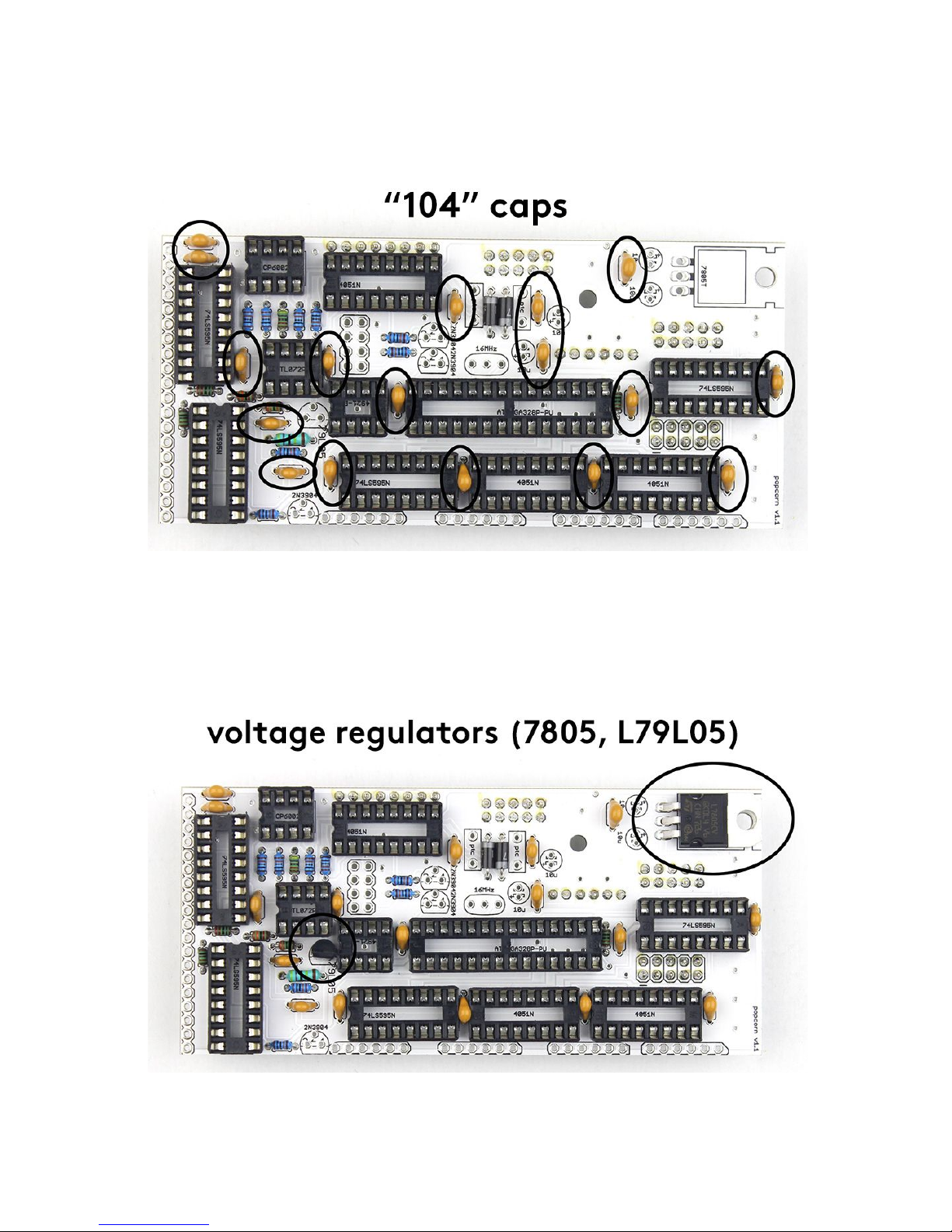
CAPACITORS
Let’s do the 100nF ceramic capacitors now. There are seventeen of them (marked “104” on itself).
VOLTAGE REGULATOR
Proceed to the 7805 voltage regulator. Bend its legs close to the body first. Insert it then to the spot
and make it lay on the PCB.
There is also another voltage regulator (L95L05). Add it to the right spot and be aware of the
orientation. It has to match the outline on the PCB.
9
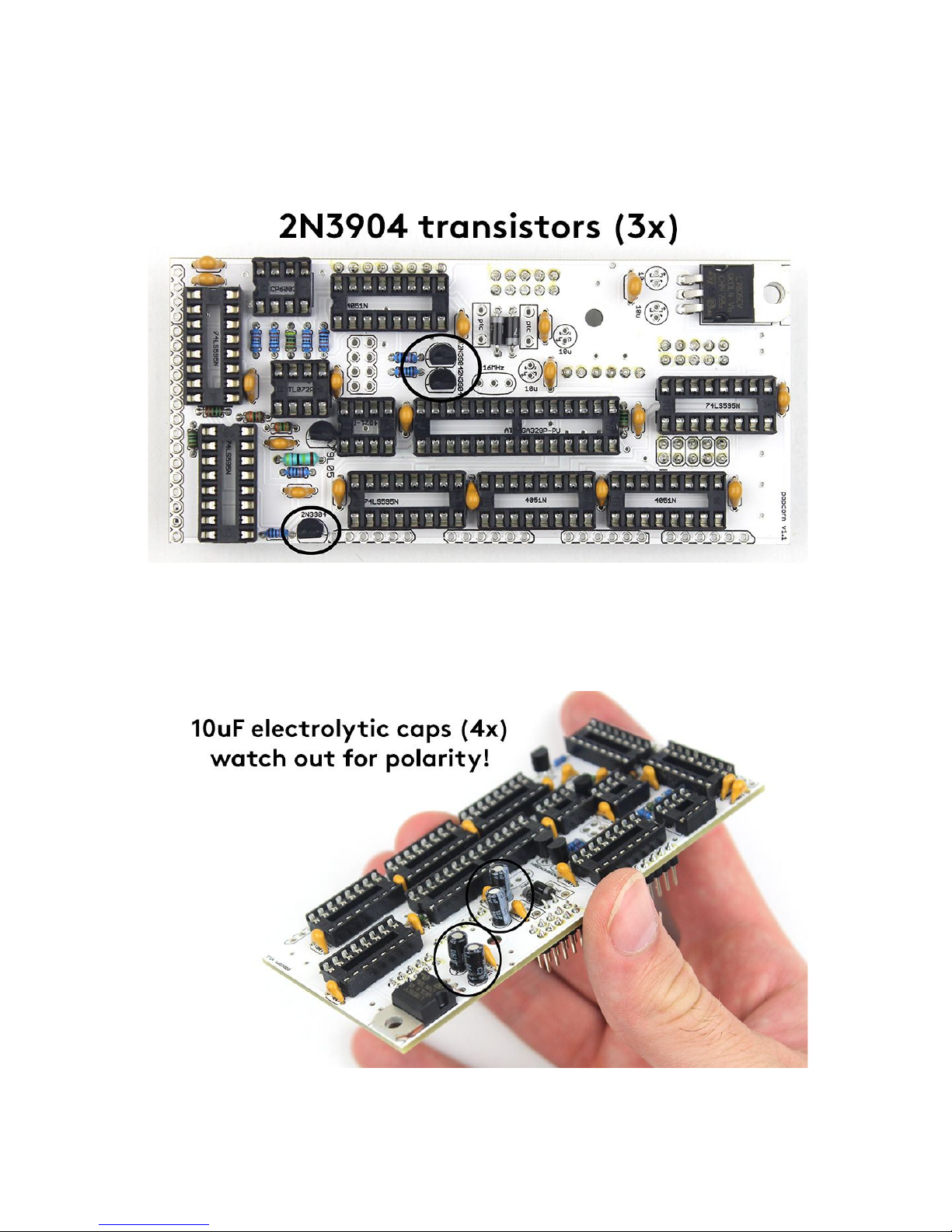
TRANSISTORS
Add three transistors (2N3904). Just be aware of the right orientation again!
ELECTROLYTIC CAPACITORS
Let’s do the electrolytic caps (4x 10μF). These ones are polarized! There is a plus (+) sign on the
PCB that has to match the longer lead of the electrolytic capacitor (actually the minus (–) side is also
marked on the body of the capacitor with a white strip).
10

FUSES
Solder the two fuses right on the rectangular spot signed “PTC”. These parts look quite similar to
capacitors so don’t let it confuse you.
RESONATOR
Insert also the resonator (the orange component with 3 leads). This part is not polarized so you can
insert it in any direction.
11
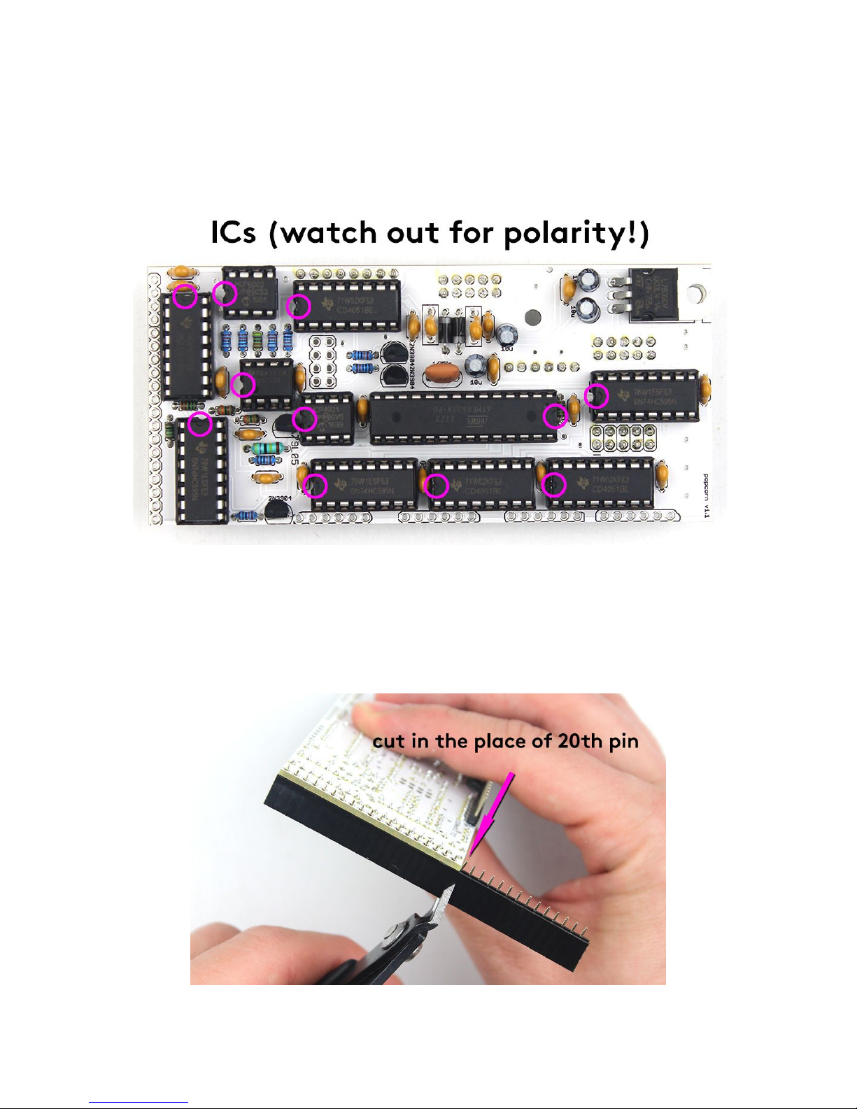
INSERTING ICs
Next don’t forget to place ICs into the sockets (1x TL072, 1x MCP4921, 1x MCP6002, 3x CD4051BE,
4x 74HC595, 1x Atmega). There is a notch on each IC that should match with the notch on the
socket (for TL072 is relevant the dot on it). Installing ICs can be also a little tricky. You should bend
the IC leads in slightly with your fingers. Then press all the leads into the sockets in one shot.
PREPARING FEMALE HEADERS
As you can see two female pinheaders left. You can prepare them now. Use your flush cutters to
get the lengths of 19 and 29 pins. You will always lose one pin when cutting the female headers, so
be sure to cut it always after the last required pin - see the picture to check where to cut to get 19 pin.
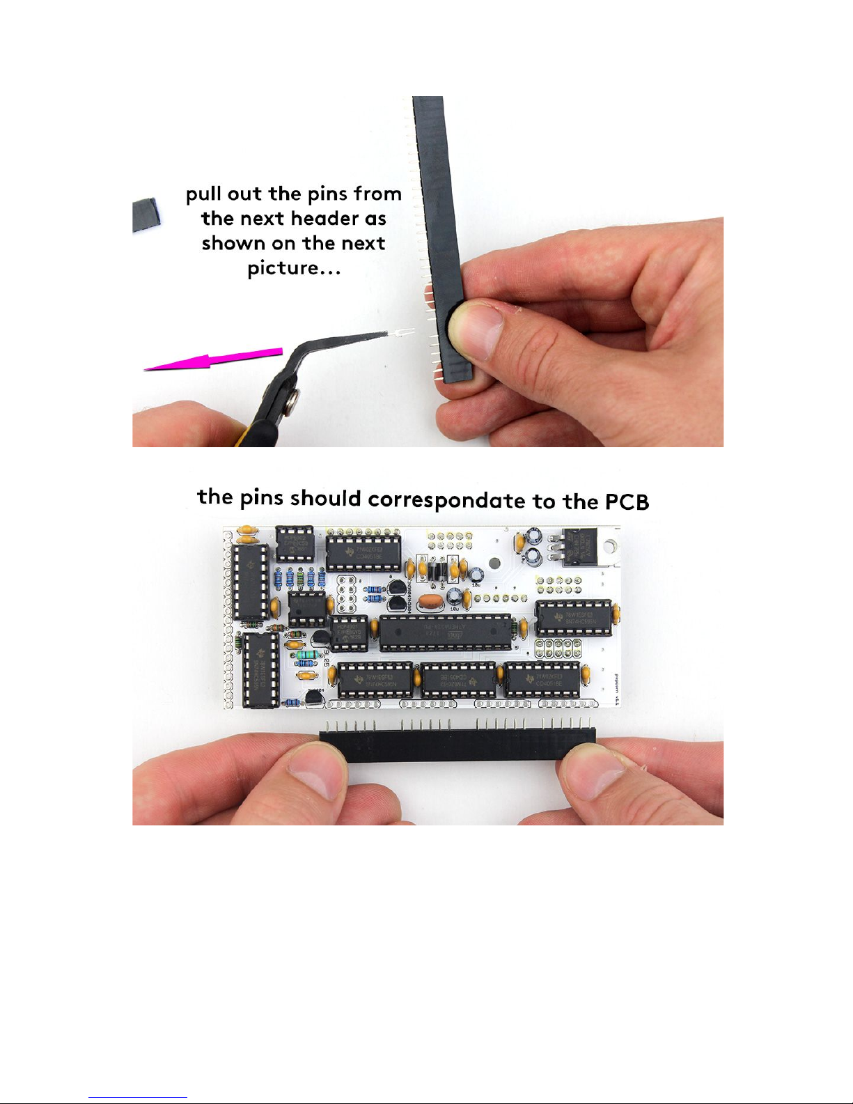
Then you have to adjust the 29 pin one by pulling out some pins. See the photos again. Hold on with
these parts then. You will use them in later steps
12
For now you are finally done with the bottom board. Make the last check that all parts are on the right
place and everything is properly soldered.
13

TOP BOARD
RESISTORS
Let's move to the top PCB now. Again, start with the resistors:
-220R (6x), 1k (9x)
14
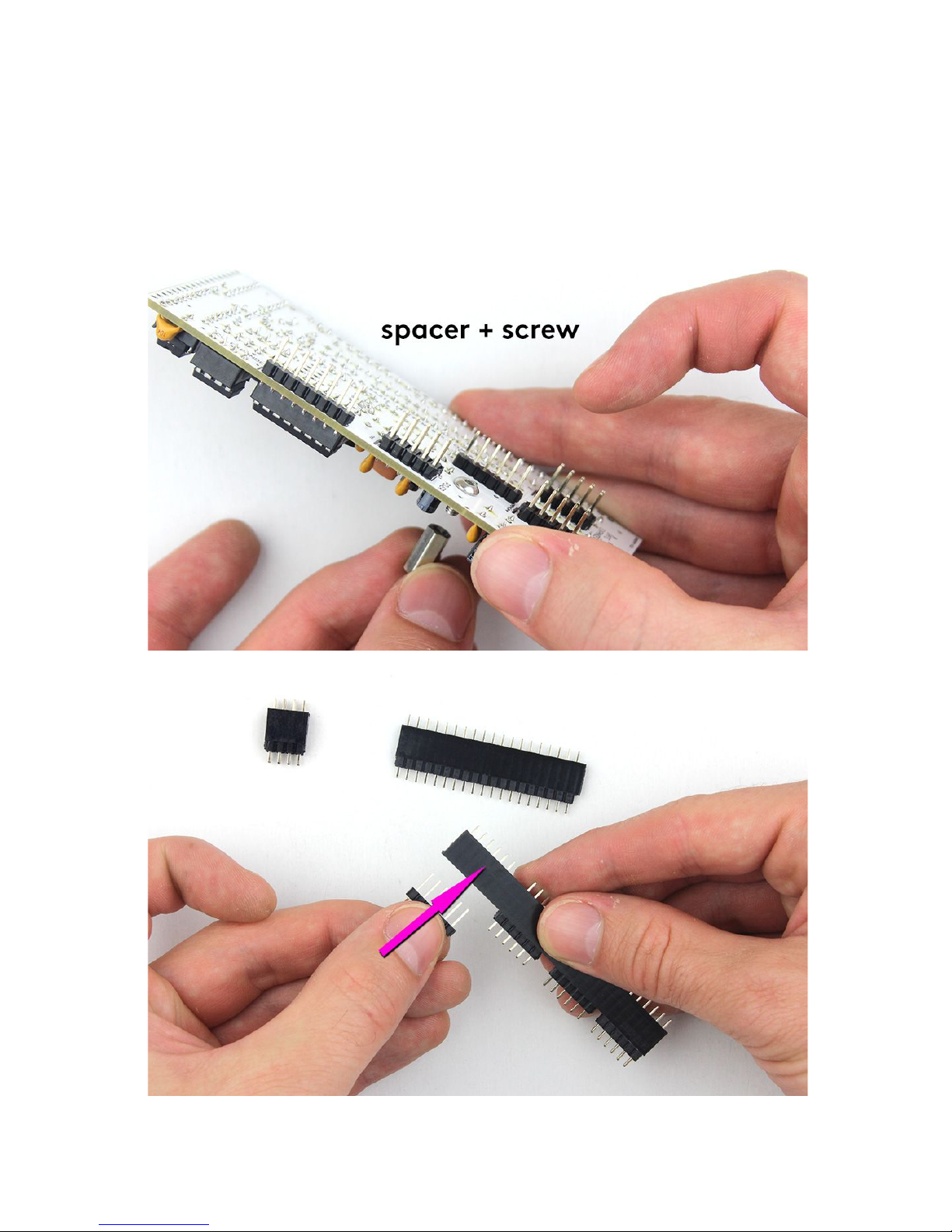
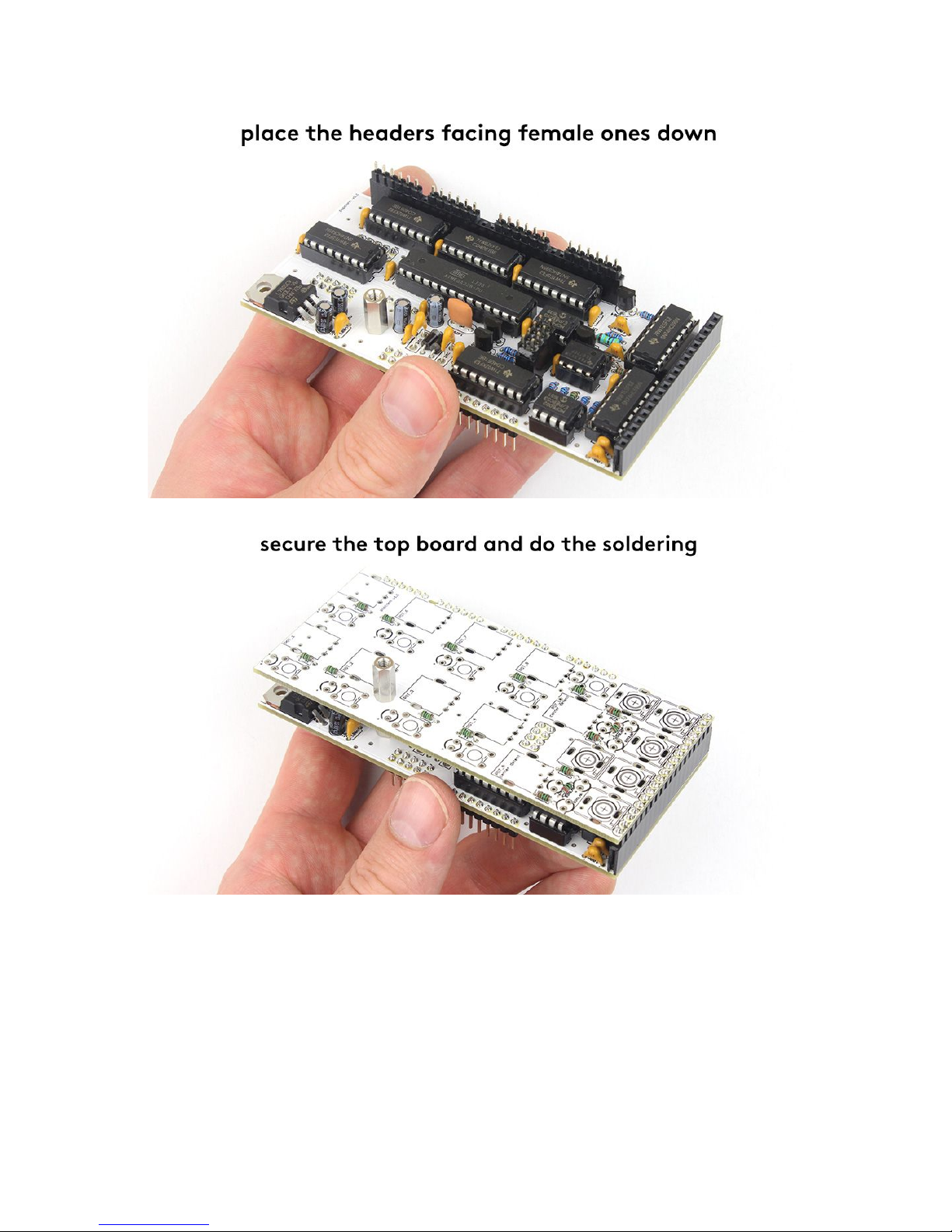
PINHEADERS
Now it’s time to connect the boards with pinheaders.
1) Mount the spacer with the screw to the bottom board first.
2) Insert male headers into the female ones.
3) Put the headers on the bottom board facing the female ones down.
4) Place the top board on and secure it with the other spacer. Check the position and do the
soldering of headers finally.
15
16

JACKS, POTENTIOMETERS, BUTTONS & LEDS
You are almost done. Let's do the rest of the components by just putting them in first (no soldering
yet! It starts at point 8!):
1) Unmount the top board.
2) Insert green LEDs (9x) -watch out for orientation! (the longer lead has to go into the plus
(+) hole signed on PCB). Insert also the transparent ones (6x) - watch out for orientation
again!
3) Insert buttons (9x) - be sure they’re at the right angle and right on the board.
4) Try the center detent potentiometers (2x) and place them at their spot - be sure they’re
placed in the right angle and they’re right on the board. Then do also the rest of
potentiometers (8x).
5) Insert jack connectors (6x).
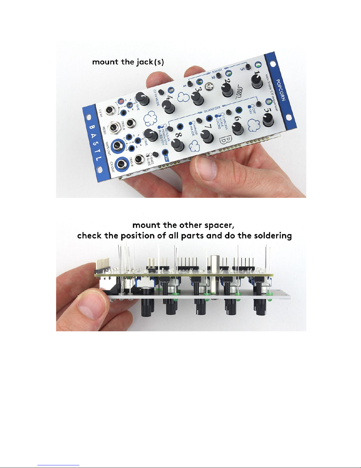
6) Mount the spacer to the front panel.
7) Place the front panel on and mount the jacks (you don’t have to mount them all as you have
to unmount them in the next step).
8) Mount the spacer with the other one. Check the position of all the parts if they are flat on the
board and at the right angle, push the LEDs to the panel and do the soldering (SOLDERING
TIP: you can start by soldering just one of the leg at each component so you can make
adjustments easier by reheating)
17

18
19
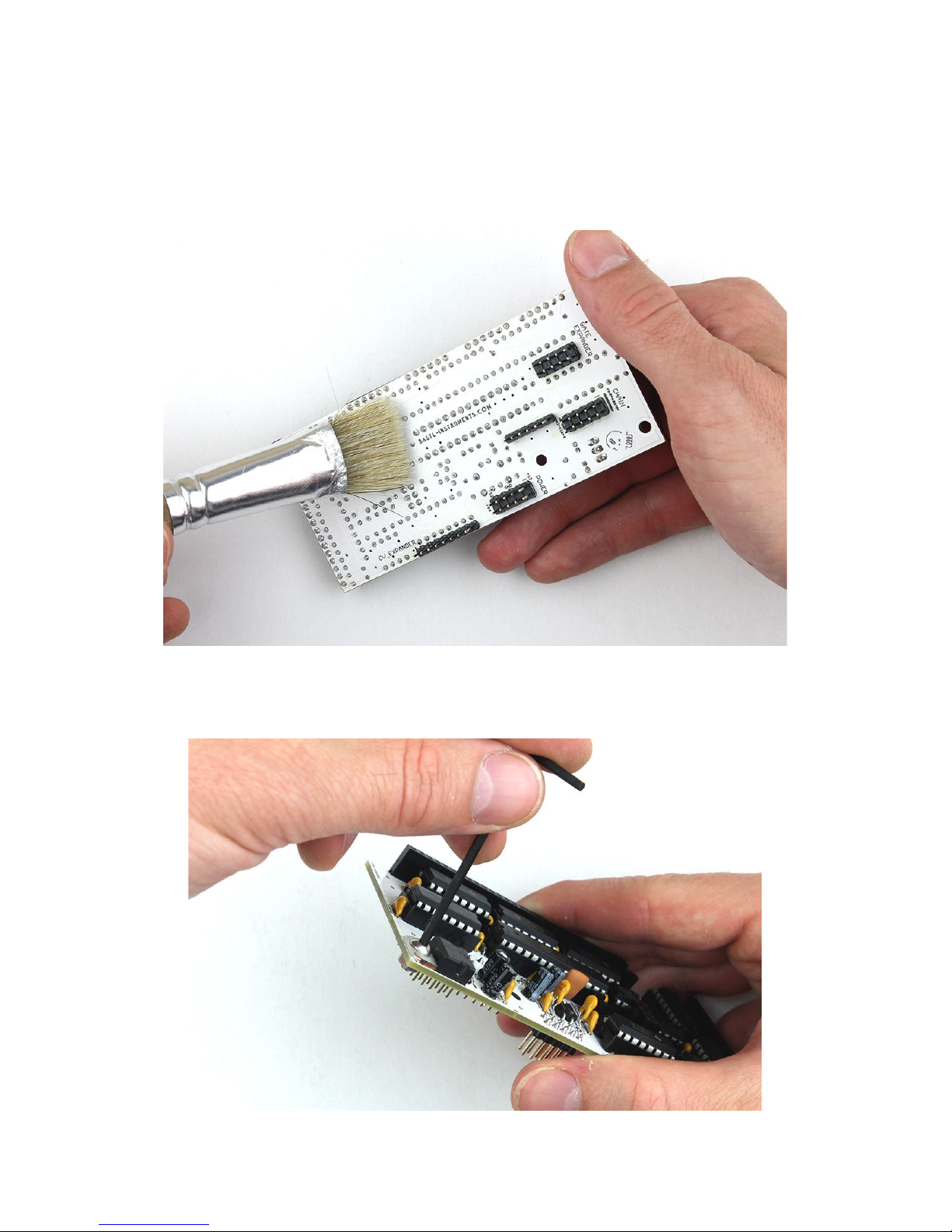
CLEANING (OPTIONAL)
After the soldering is done you might want to clean your PCB. You can use e.g. isopropyl alcohol. Put
some of the liquid all over the PCB using the brush (be aware to not let it flow into the pots), let it act
for a while and sweep it off. Then just let it dry. You can repeat these steps until you are satisfied with
the result.
SCREW + NUT
You can also mount the screw and nut to the voltage regulator now.
20
Table of contents
Other Bastl Instruments Recording Equipment manuals

Bastl Instruments
Bastl Instruments 60 KNOBS User manual

Bastl Instruments
Bastl Instruments SoftPop User manual

Bastl Instruments
Bastl Instruments SixtyKnobs User manual

Bastl Instruments
Bastl Instruments KOMPAS User manual

Bastl Instruments
Bastl Instruments Knit Rider User manual

Bastl Instruments
Bastl Instruments GRANDPA v1.0 User manual

Bastl Instruments
Bastl Instruments Timber User manual

Bastl Instruments
Bastl Instruments Tea Kick User manual

Bastl Instruments
Bastl Instruments Noise Square User manual

Bastl Instruments
Bastl Instruments Thyme User manual


