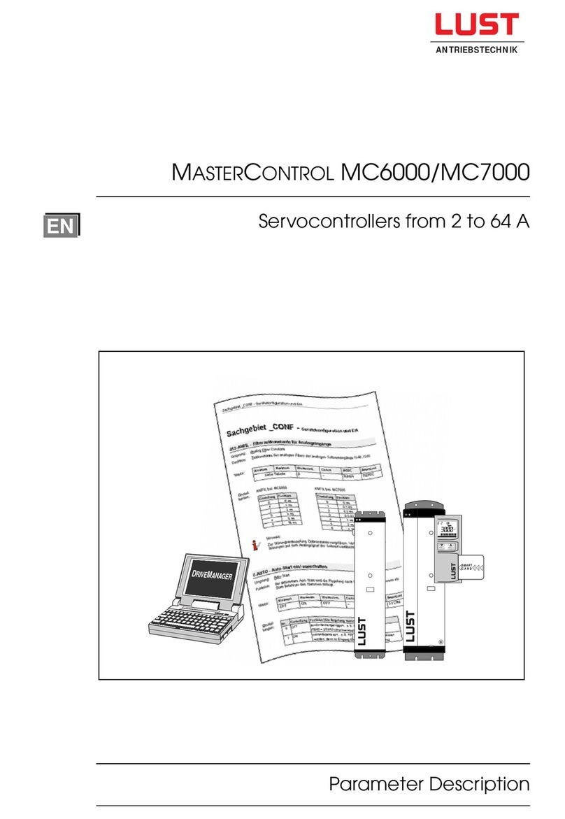
Lust MASTERCONTROL MC6000 Series User manual

Servocontroller 4 - 64 A
stop
return start
enter
SMART
CARD
CTRL
min-1
Instruction Manual
MASTERCONTROL MC6000
ANTRIEBSTECHNIK

The MASTERDRIVE System
Instruction Manual
for MC6000 Series
Servocontrollers
Valid from Software-Version: V1.1
Item Number: 0792.20B.0-02
Version: December 1995
We reserve the right to make technical changes
Terminal Module
EKL 300
Mains filter
Line choke
Mains
connection
stop
return start
enter
SMART
CARD
CTRL
min-1
InterBus-S Interface
CAN-Bus Interface
Servocontroller
MC6000
synchronous
servomotors
series PSx
asynchronous
servomotors
series ASx
various cables
PC Interface
SMARTCARD for easy matching
of servocontrollers to the motors
I/O Module1
SMARTCARD storages
all parameters
RS485
SMART
CARD
SMART
CARD

Dear Customer
Thank you for the trust that you have placed in us by purchasing the LUST
MASTERDRIVE drive system.
Installation and commissioning must only be carried out by a trained engineer. Please
take the time to read the instructions carefully. Following the instructions meticulaously
will you time and avoid uncertainty and questions at the commissioning stage.
It is essential to read the Instruction Manual because incorrect use of the servodrive can
damage both the servodrive itself and also other parts of the installation. Because of the
rotatingpartsofthedriveandthehighvoltagesinvolved,thistypeofequipmentispotentially
hazardous to human life.
If after reading the instructions you still have questions, do please contact us.
LustAntriebstechnikGmbH
Gewerbestr. 5-9
D-35631 Lahnau
Germany
Tel: +49 6441 966 -0
Fax: +49 6441 966 -137

wait 2 minutes
after power-off
Symbols
⇒Danger! Danger of death by electrocution or rotating machinery.
⇒Warning:you must follow this instruction.
⇒Warning: before opening the equipment, disconnect from the mains and wait
approximately two minutes for the DC link capacitors to discharge.
⇒Prohibited: incorrect operation may cause damage to equipment.
⇒Useful tip, Note.

↓↓
↓↓
↓
☞1
☞2
☞3
4
5
6
7
8
9
10
11
☞12
Safety Instructions
General, Manufacturer's Declaration, CE and EMC
Technical Specifications of Servocontrollers
Installation Instructions
Installation, Commissiong
Important Instructions for Operation
Electrical Connections
EMC, Connection to the mains power supply, motor, terminals,
encoder, RS485 and Bus system
Software Overview
Using KEYPAD and SMARTCARD
Configuration
Assigning input and output functions
Processing of reference values, Emergency Stop etc
Structure of controls
Torque control, speed control and position control
Displays and Error Messages
Parameter Description
by Subject Area
I/O Module 1 and EKL300
Servomotor Project Data
Technical specifications, dimensional drawings, axial and radial
loads, cooling, holding brake, etc
Index
Parameter Overview (Table)
Signposts
Especially important
for commissioning:

Quick Finder
1 General .............................................................................................................1-1
1.1 Safety instructions .............................................................................................1-1
1.2 Intended use ......................................................................................................1-1
1.3 Manufacturer's Declaration for Servocontrollers ................................................1-2
1.4 Manufacturer's Declaration for Servomotors......................................................1-4
1.5 MC6000 with CE Mark ....................................................................................... 1-6
1.6 Instructions for correct EMC installation............................................................1-8
1.7 What are the main benefits of the MASTERDRIVE System?...................................1-9
1.8 Details for ordering the MC6000 Servocontroller ............................................. 1-10
1.9 MC6000 Servocontroller Models...................................................................... 1-11
1.10 Accessories for the MC6000 Servocontroller ...................................................1-12
2 Technical Specifications for Servocontrollers ..............................................2-1
2.1 Design and Layout.............................................................................................2-1
2.2 Output - motor....................................................................................................2-2
2.3 Input - power side ..............................................................................................2-2
2.4 Resolution of angle of rotation ...........................................................................2-2
2.5 Ambientconditions.............................................................................................2-3
2.6 Dimensions and weights ....................................................................................2-3
2.7 Mounting instructions .........................................................................................2-4
3 Installation and Commissioning.....................................................................3-1
3.1 Instructions for installation .................................................................................3-1
3.2 Installation of drive system.................................................................................3-2
3.3 Commissioning of the drive system ...................................................................3-2
3.4 Important tips ..................................................................................................... 3-4
4 Electrical Connections ....................................................................................4-1
4.1 System connection diagram...............................................................................4-1
4.2 Electromagneticcompatability ...........................................................................4-2
4.3 Power Terminals .............................................................................................. 4-3
4.3.1 Mains power supply connection ......................................................................... 4-3
4.3.2 Motor connection ...............................................................................................4-4
4.3.3 Connection of thermistor....................................................................................4-6
4.3.4 Connection of braking resistor ...........................................................................4-7
4.3.5 DC link terminals.............................................................................................. 4-11
4.3.6 MC6000 protection functions ........................................................................... 4-11
4.4 Control Connections ..................................................................................... 4-12
4.4.1 Control terminal allocation................................................................................ 4-12
4.4.2 Specification of control connections.................................................................4-13
4.4.3 Key to input and output codes..........................................................................4-14
4.4.4 Wiring control terminals ...................................................................................4-14
4.4.5 ENPO input (ENable POwer stage) .................................................................4-17
4.4.6 Input of current reference signals.....................................................................4-17
4.5 Encoder connection ...................................................................................... 4-18
4.5.1 Resolver cable KRX-Nxx, KRX-KS-xx ............................................................. 4-18
4.5.2 Encoder cable KG1-KSxx, KG2/3-KS-xx .........................................................4-19

4.6 RS485 serial interface......................................................................................4-20
4.7 Encoder simulation .......................................................................................... 4-22
4.8 InterBus-S-Interface (C1 and C7) ....................................................................4-24
4.9 CAN-Bus-Interface (C2)................................................................................... 4-25
5 MC6000 software and overview ......................................................................5-1
6 System software ..............................................................................................6-1
6.1 Layout of the KeyPad.........................................................................................6-1
6.2 Using the controls ..............................................................................................6-2
6.2.1 General..............................................................................................................6-2
6.3 Controls .............................................................................................................6-2
6.4 LCD Display.......................................................................................................6-3
6.5 Control levels .....................................................................................................6-4
6.6 Examples for setting parameters .......................................................................6-5
6.7 Overview of Menu Structure ...........................................................................6-7
6.7.1 The VAL Menu ................................................................................................... 6-7
6.7.2 The PARA Menu ................................................................................................6-8
6.7.3 The CTRL Menu ..............................................................................................6-10
6.7.4 The CARD Menu .............................................................................................6-12
6.8 Setting the parameters for the MC6000 ...........................................................6-13
7 Configuration Software ................................................................................... 7-1
7.1 Function selectors...........................................................................................7-2
7.1.1 Input Functions ..................................................................................................7-3
7.1.2 Output Functions ...............................................................................................7-4
7.1.3 Fixed inputs FIF0 und FIF1................................................................................7-4
7.2 Reference Value Input ..................................................................................... 7-5
7.2.1 Short description of reference inputs..................................................................7-5
7.2.2 Description of reference inputs ..........................................................................7-5
7.2.3 Setting reference inputs ..................................................................................... 7-9
7.3 Special functions ........................................................................................... 7-10
7.3.1 Emergency Stop ..............................................................................................7-10
7.3.2 Automatic start................................................................................................. 7-10
7.3.3 Motor potentiometer function (MOP)................................................................ 7-11
7.3.4 OS00 output as PWM output ........................................................................... 7-11
7.3.5 Torque limitation (SCALE)................................................................................7-12
7.4 Examples of applications .............................................................................. 7-13
7.4.1 Example: analog reference value input ............................................................7-13
7.4.2 Example: reference value input using serial interface ......................................7-15
7.4.1 Example: switching from fixed reference values ..............................................7-16
7.4.1 Example:Analog reference value input with switching .....................................7-18
8 Control Software.............................................................................................. 8-1
8.1 General control structure ...................................................................................8-3
8.2 Torque control mode ..........................................................................................8-4
8.3 Speed Control Mode ........................................................................................ 8-5
8.3.1 Setting speed control .........................................................................................8-7
8.3.2 Speed in field weakening ...................................................................................8-9
8.4 Position Control...............................................................................................8-9
8.4.1 Position control without pre-control ..................................................................8-10
8.4.2 Position control mode ......................................................................................8-10

9 Displays and Error Messages .........................................................................9-1
9.1 Operating display...............................................................................................9-1
9.2 Error Messages................................................................................................9-1
9.2.1 Warnings and errors in the Servocontroller ........................................................9-2
9.2.2 KeyPad operator errors......................................................................................9-4
9.2.3 Errors when using SmartCard............................................................................9-4
9.2.4 Trouble shooting ................................................................................................9-5
10 Description of Parameters ............................................................................ 10-1
10.1 System for Parameter Names ....................................................................... 10-1
10.1.1 Areas _ENCD, _MOT, _TCON, _SCON, _PCON ............................................ 10-1
10.1.2 Other areas andVAL Menü..............................................................................10-3
10.2 VAL Menu Parameters ...................................................................................10-4
10.3 PARA Menu Parameters ................................................................................10-5
10.3.1 Configuation area (_CONF) ............................................................................10-7
10.3.2 Encoder area (_ENCD).................................................................................. 10-19
10.3.3 Option slot 1 (_OPTN1) ................................................................................. 10-21
10.3.4 Option slot 2 (_OPTN2) ................................................................................. 10-21
10.3.5 Motor area (_MOT) ........................................................................................10-22
10.3.6 Torque control area (_TCON).........................................................................10-25
10.3.7 Speed control area (_SCON)......................................................................... 10-26
10.3.8 Position control area (_PCON).......................................................................10-29
10.3.9 Serial interface area (_SIO) ........................................................................... 10-30
10.3.10 KEYPAD area (_KPAD) ....................................................................................10-33
10.3.11 Safety and error reaction parameters area (_SCTY)...................................... 10-37
10.3.12 Custom software area (_USER).....................................................................10-41
10.3.13 Reference value input area (_REF) ............................................................... 10-42
11 Description of I/O Module 1 (AH1) and EKL300........................................... 11-1
11.1 I/O Module 1 .................................................................................................... 11-1
11.2 Terminal allocation I/O Module1 ....................................................................... 11-2
11.3 EKL300............................................................................................................ 11-3
11.4 Software description I/O Module 1 ................................................................... 11-5
12 Servomotor Design Specifications............................................................... 12-1
12.1 Synchronous and Asynchronous Servomotor series........................................12-1
12.2 Ordering details for ASx and PSx Servomotors................................................12-2
12.3 Servomotor models..........................................................................................12-3
12.4 Basic versions of Servomotors ........................................................................12-5
12.5 Typical M-n graph for Servomotors ..................................................................12-6
12.6 Technical specifications:Asynchronous Servomotors ASx-xx ..........................12-7
12.7 Technical specifications:synchronous Servomotors PSx-xx............................12-8
12.8 Dimensions of Servomotors...........................................................................12-10
12.9 Dimensions for shaft, flange and foot............................................................. 12-11
12.10 Dimensions for motors with self cooling and external cooling ........................ 12-13
12.11 Permissible axial and radial loads .................................................................. 12-14
12.12 Technical specifications:shape and shaft seal IP65....................................... 12-15
12.13 Technical specifications:self cooling and external cooling .............................12-16
12.14 Technical specifications:holding brake .......................................................... 12-18
Index
Parameter Overview

MC6000 Instruction Manual 1-1
1 General
1.1 Safety Instructions
Servodriveshavehigh voltage exposedmetalcomponentsandmay also havemovingorrotating
parts and hot surfaces, so they do of course represent a danger to human life.
To prevent serious injury or major damage, only qualified personnel who are trained in working
on electrical drives may work on the equipment. To be qualified in this sense a person must be
familiar with the arrangement, installation, commissioning and operation of Servodrives and
possess appropriate qualifications to work on them. He must read the instruction manual in
detail before installation and commissioning and must follow the safety instructions at all times.
(IEC 364 and CENELEC HD 384 or DIN VDE 0100 and IEC-Report 664 or VDE 0110 and national health and safety
regulations or VBG 4)
Repairs to Servodrive components may only be carried out by the manufacturer or by repair
centres authorized by the manufacturer. Unauthorized opening of the equipment and unskilled
repairs may result in injuries and damage.
1.2 Intended use
Servodrives are equipment designed for incorporating in electrical installations or machines.
The commissioning of the Servodrive (ie commencing operation as intended) is prohibited until
such time as it has been confirmed that the machine complies with the requirements of EC
Directive 89/392/EEC (Machinery Directive). EN60204 must be observed.
Commissioning (ie starting normal intended operation) is only permitted under conditions of
strict adherence to the EMC Directive (89/336/EEC).
For the LowVoltage Directive 73/23/EEC the harmonized standards in the series prEN 50178/
DINVDE 0160inconjunctionwith EN60439-1/DINVDE 0660part500and EN60146/DINVDE
0558 are used for Servodrives.
Technical specifications and connection details should be read off the nameplate and from the
documentation and must be strictly observed.
Servodrives must be protected from excessive loads. In particular no components must be
distorted or insulation/separation arrangements be changed during transport and handling.
Servocontrollers and Servomotors contain electrostatic components which are vulnerable and
can easily be damaged by inappropriate handling. Electrical components must not be
mechanically damaged or destroyed.
Any work on Servodrives which are live must be strictly in accordance with with currently valid
national health and safety regulations (eg VBG 4).
Electricalinstallation mustbecarried outinaccordance withtheapplicable regulations(relating
toconductor crosssection,protection,and protectiveconductorconnectionetc). Further details
are contained in the documentation.
Electronicequipmentisnotinherently fail-safe, sothe usermust acceptresponsibility forensuring
that the drive cannot become dangerous in case of failure.
Ifthe Servodriveisto beusedfor specialapplications(eg inan explosive environment)then the
relevant standards and regulations (eg EN50014 and EN50018) must be followed.

MC6000 Instruction Manual
1-2
1.3 Manufacturer's Declaration for Servocontrollers

MC6000 Instruction Manual 1-3

MC6000 Instruction Manual
1-4
1.4 Manufacturer's Declaration for Servomotors

MC6000 Instruction Manual 1-5

MC6000 Instruction Manual
1-6
1.5 MC6000 with CE Mark
Copy of the CETest Certificate as as exaple for MC6404 and MC6408:

MC6000 Instruction Manual 1-7
Copy of Summary ofTest Results as an example for MC6404 and MC6408:

MC6000 Instruction Manual
1-8
L1
L2
L3
M
3~
G
PE
RB RB +-
L1
L2
L3
W
V
U
PTC
PTC
1
2
3
4
5
6
7
8
9
10
11
12
13
14
... with original
encoder cable
... with screened
control cable
... with good
star grounding
... with mains filter
(see section 4.2)
... with screened
mains cable
... with screened
motor cable
asynchronous
or synchronous
Servomotor
resolver or
optical encoder
MC6000 Servocontroller
X5
X1
X3
X2
X10
control terminals
≥ 10 mm2
star grounding point
(
main
g
round
)
in cabinet
1.6 Instructions for Correct EMC Installation
CE including EMC:
The MASTERDRIVE drive system has been designed such that it complies not only with the low
voltage directive, but also the EMC directive (assuming appropriate installation) - and even the
strictdirective fordomesticuse. Conformancetesting wascarriedout intherenownedSchenck
laboratories under laboratory conditions and there is no guarantee that these findings can be
transferred to a Servodrive installed in a specific machine or installation.
Instructions for the best possible installation are shown in the next diagram.
How to achieve correct EMC installation...
Note:
Complete instructions for wiring the Servodrive are contained in Section 4.

MC6000 Instruction Manual 1-9
stop
return start
enter
SMART
CARD
CTRL
min-1
• One Servocontroller for asynchronisous and synchronisous motors
⇒reduced training and documentation costs.
⇒reduced cost of spares in stock
•KEYPAD - one controller for Servocontrollers and frequency inverters
⇒reduced familiarization and documentation costs
• Chipcard with motor specifications and complete
controller matching
⇒high level of safetywhen commissioning
⇒reduced commissioning costs
• Equipment flexibility with retrofit accessories
⇒high degree of flexibility for future requirements
• Servocontroller with integrated positioning and sequence control
⇒reduced space requirements in cabinet
⇒reduced wiring costs
⇒reduced drag errors and reduced load on central control
• System solution with asynchronous and synchronous motor range
⇒this gives you the capacity to create the ideal solution in both technical and economic
terms
• CE conformity
⇒this means that acceptance of your machine or installation will be straightforward
without the drive being a concern.
1.7 What are the main benefits of the MASTERDRIVE System?
stop
return start
enter
SMART
CARD
CTRL
min-1
SMART
C A R D
Asynchronous Servomotors
→ideal economic solution
→wide speed setting range with
constant maximum performance output
→maintenance-friendly
Synchronous Servomotors
→ultra compact
→optimum dynamics
→high precision torque control

MC6000 Instruction Manual
1-10
1.8 Details for ordering the MC6000 Servocontroller
The Servocontroller model is identified by the order code. Non-standard versions are identified
by the addition of model codes to the order code.
In the model combination represented, there is standardization on one model at each stage (eg
control, encoder interface etc). Each model code has a special meaning; see Servocontroller
models.
Non-listed controllers also use model codes which are not detailed here.
The model code 1 - 5 is separated by a comma and these codes can be added in any
order.
MC6 xxx
54321
locations 1 - 5
Example
MC6408 , KP0 , D2 , C2
with CAN bus interface
with encoder interface for
evaluating sin/cos encoder
withoutKP100 controller
MC6 xxx Continuous current (RMS), see MC6000 Technical
Specifications
Mains voltage, see MC6000 Technical Specifications
MASTERCONTROL MC6000 Series
Model code for non-standard models
Standardmodel: •with KP100 control unit
•with encoder interface for evaluating resolvers
•for MC6404 to MC6416: BR1
for MC6432 and MC6464:BR3
with brake chopper power electronic (10% duty
cycle) and braking resistor in heat sink
with braking chopper power electronic (100%
duty cycle) for direct connection to an external
braking resistor
Order code/type code (standard version)

MC6000 Instruction Manual 1-11
Location Version Short Description Described
code in
Standard With KP100 multifunction control unit. Section 6
KP0 Without KP100 multifunction control unit –
Standard Encoder interface for evaluating resolvers. Section 4.5
D2 Encoder interface for evaluating the latest optical encoders, Section 4.5
incremental sin/cos outputs and simultaneous absolute position
information as single turn and multi turn variants.
Standard Without application hardware in slot X7 –
AH1 PLC compatible I/O expansion with 8 inputs and 4 outputs. Section 11
The I/Os are fully programmable.
1.9 MC6000 Servocontroller Models
Control
1
2
Encoder
Interface
3
Application
Hardware
The model codes on the nameplate identify how the device is equipped.
4
Bus
Interface
5
Braking
chopper
version
Standard Without bus interface in slot X6 –
C1 INTERBUS-S interface for local bus link (IBS-L) Section 4.8
C2 CAN-Bus interface (CAN) Section 4.9
C7 INTERBUS-S interface for remote bus connection (IBS-F) Section 4.8
Standard Braking chopper power electronics (10% duty cycle) and Section 4.3.4
(BR1) braking resistor in heat sink.
BR3 Braking chopper power electronics (100% duty cycle) without Section 4.3.4
braking resistor (standard version for MC6432 and MC6464).

MC6000 Instruction Manual
1-12
1.10 Accessories for the MC6000 Servocontroller
Order Description
Code
KP100 KP100 multifunction control unit for operating the Servocontroller and
frequency inverter
0000.ZSC SMARTCARD without data
0792.ZSC, SMARTCARD for adapting the MC6000 Servocontrollers to the
xxx-xx-xxxx Servomotor series ASx and PSx
Accessories for fitting to the Servocontroller
Order Description
Code
EKL300 Terminal module for external wiring of control terminals of application
hardware AH1 and AH2.With connecting cable (KSS252).
KSS252 Connecting cable to link MC6000 Servocontroller and EKL300 terminal module .
Connecting cable length 1.8m.
LBSKK200 Interface converter cable: RS485 to RS232. Cable length approximately 2m.
Accessories for fitting externally
Other manuals for MASTERCONTROL MC6000 Series
1
This manual suits for next models
6
Table of contents
Other Lust Controllers manuals