Table of Contents 3
© Lutz-Jesco GmbH 2021
Subject to technical changes.
210527
BA-22404-02-V03
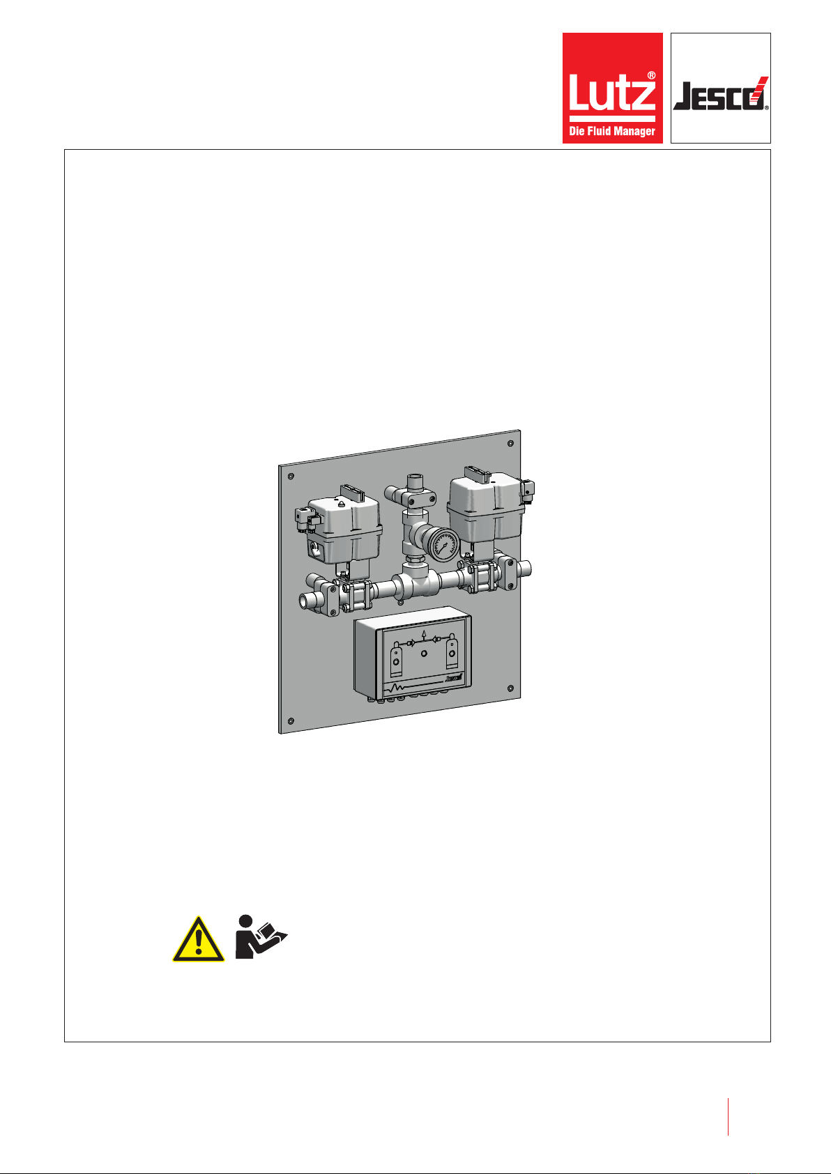
Chlorine changeover unit C 7520 Operating instructions
Table of Contents
1 Notes for the Reader ..........................................................4
1.1 General non-discrimination......................................................4
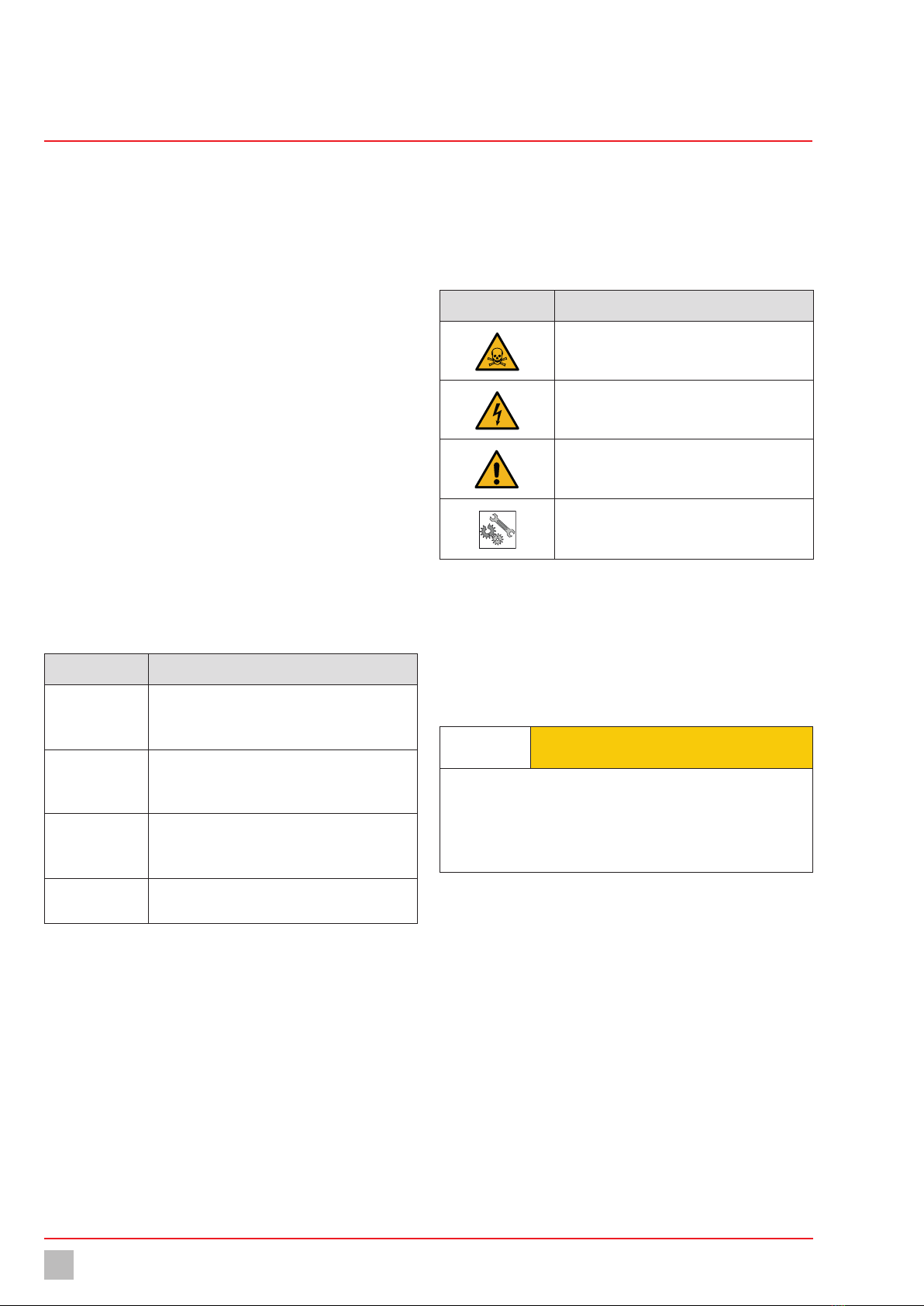
1.2 Explanation of the signal words ................................................4
1.3 Explanation of the warning signs ..............................................4
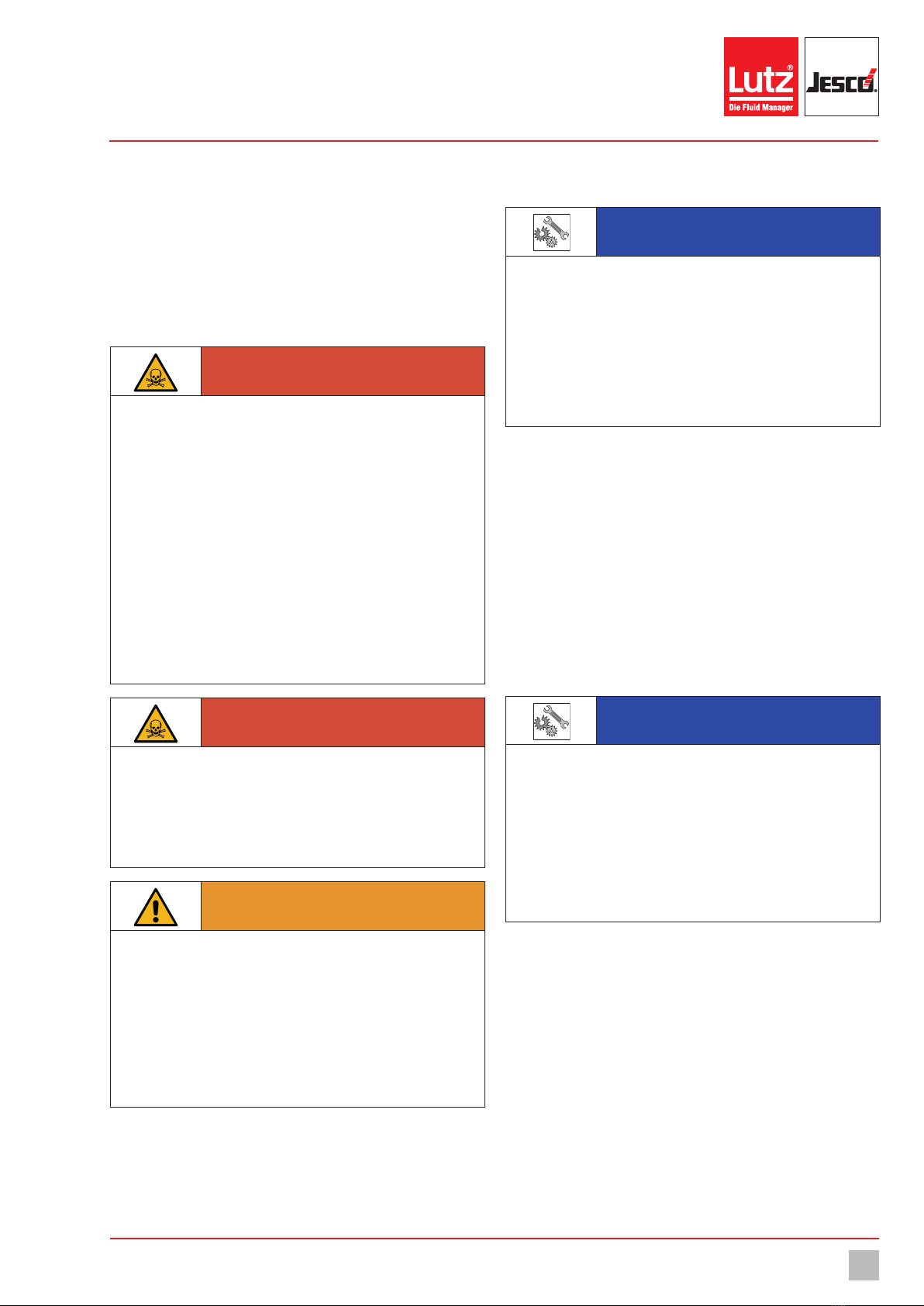
1.4 Identification of warnings.........................................................4
1.5 Identification of action instructions ...........................................4
2 Safety .................................................................................5
2.1 General warnings.....................................................................5
2.2 Information about chlorine .......................................................5
2.3 Hazards due to non-compliance with the safety instructions .....5
2.4 Working in a safety-conscious manner .....................................6
2.5 Personal protective equipment.................................................6
2.6 Personnel qualification.............................................................6
2.7 Personnel tasks .......................................................................6
3 Intended use ......................................................................7
3.1 Notes on product warranty .......................................................7
3.2 Intended purpose.....................................................................7
3.3 Prohibited dosing media...........................................................7
4 Product description ...........................................................8
4.1 Scope of delivery .....................................................................8
4.2 Design and function .................................................................8
4.3 Rating plate .............................................................................9
5 Technical data..................................................................10
6 Dimensions ......................................................................11
7 Installation .......................................................................12
7.1 Installation location................................................................12
7.2 Installing the device ...............................................................12
7.3 Hydraulic installation..............................................................12
7.4 Electric installation.................................................................13
7.5 Completing the installation.....................................................16
7.6 Installation example...............................................................17
8 Control..............................................................................18
8.1 Controls.................................................................................18
8.2 Operating modes ...................................................................18
9 Commissioning ................................................................20
9.1 Inspecting the pressure system..............................................20
9.2 Turning on the device .............................................................21
9.3 Adjusting the switching contact..............................................21
10 Operation..........................................................................22
10.1 Tank change ........................................................................22
10.2 Shutting down in an emergency ...........................................22
10.3 Optical check.......................................................................22
11 Shutdown.........................................................................23
11.1 Short-term shutdown...........................................................23
11.2 Long-term shutdown ...........................................................23
11.3 Disposal of old equipment....................................................23
12 Maintenance ....................................................................24
12.1 Maintenance intervals..........................................................24
12.2 Maintenance accessories.....................................................24
12.3 Preparing the system for maintenance .................................24
12.4 Maintenance on the ball valve ..............................................24
12.5 Cleaning the pressure gauge................................................26
12.6 Functional control ................................................................27
12.7 Finishing maintenance.........................................................27
13 Troubleshooting ...............................................................28
14 Spare parts.......................................................................29
15 EU Declaration of Conformity...........................................30
16 Declaration of no objection..............................................31
17 Warranty claim.................................................................32
18 Index.................................................................................33