Luxel Radak Power Controller II Use and care manual

PO Box 1879, 60 Saltspring Drive
Friday Harbor, WA 98250
www.luxel.com
H
He
ea
at
te
er
r
R
Re
ep
pl
la
ac
ce
em
me
en
nt
t

Heater Replacement
PO Box 1879, 60 Saltspring Drive
Friday Harbor, WA 98250
www.luxel.com
RADAK HEATING ELEMENT REPLACEMENT INSTRUCTIONS
Removing the old Heating Element
1. Mount the furnace base securely. It will
be helpful if the furnace is bolted to a
bracket held in a bench-top vise.
2. Remove wire or
foil termination
at upper and
lower ends of
heater element
where they are
attached to the
power-leads.
3. Note location and orientation of the
shorter power-lead conductor. This is
where the new lower power lead will be
installed.
4. Loosen the 4-40 set screws retaining
both upper and lower power-leads at
the copper power terminals.
5. Remove lower power lead by pulling it
out of the top of its insulator.
6. Remove the upper power lead-
Remove the copper power terminal
from the furnace base.
Slide the ceramic insulator down
almost flush with the top of heater
element support plate.
Pull the power conductor out of the
top of insulator.
Note: If it is necessary to remove the
ceramic insulators from the furnace,
they must be replaced immediately
with 1/8-inch diameter rods to prevent
misalignment of internal radiation
baffles. Baffle misalignment will
prevent re-assembly of the furnace.
7. Note that the heater element is wound
in the furnace clockwise from the
bottom (as viewed from the top).
8. Beginning at the top, remove the
heating element by remove the element
from the notch in each successive
ceramic post. Be careful to avoid
damage to the ceramic heater supports.

Heater Replacement
PO Box 1879, 60 Saltspring Drive
Friday Harbor, WA 98250
www.luxel.com
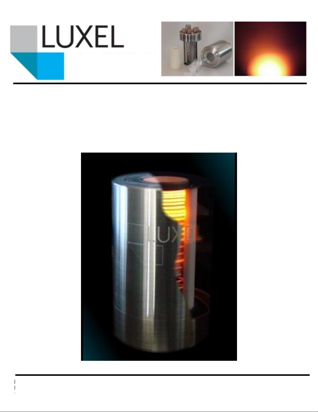
Install the New Heating Element
1. If necessary, replace the existing upper
(longer) power lead insulator.
Note: Never remove both power
lead insulators at the same time.
This will leave the lower pedestal
radiation baffles free to rotate
possibly resulting in internal
misalignment. Alignment cannot
be corrected without rebuilding the
furnace.
Insert the upper power lead
insulator into the base of the
furnace until just visible inside the
furnace.
2. Insert the upper (longer) power lead
into the upper power lead insulator.
3. Slide the upper power lead and
insulator until the insulator is just
showing out of the bottom of the
furnace.
4. Re-assemble the copper power terminal
in the following order: star washers,
ceramic insulators, copper terminal
(counter-bored side out), second set of
insulators, second set of star washes,
then 4-40 mounting screws.
Note: If the screw lengths differ,
the shorter screw is to be used in
the outside hole.
5. Push ceramic power-lead insulator
down to seat against top of the installed
copper power terminal.
6. Position the upper power lead so that
the bend in the lead is two or three wire
widths below the top of the furnace.
The upper end should point in the same
direction as the heater element
winding.
7. Secure the power-lead with the set
screw in the copper terminal.
8. Insert lower power-lead (attached to
end of pre-wound element) into its
insulator, pushing down until upper end
is aligned with bottom slot in ceramic
heater support post.
9. Tighten set screw in copper terminal to
secure.
10. Wind in heater element, beginning at
the bottom, seating element in each slot
successively. At each post check to
insure that all preceding turns are
snugly seated. Wind to top. At the last
turn, pull free end out under the upper
ring alongside the upper power
conductor.

Heater Replacement
PO Box 1879, 60 Saltspring Drive
Friday Harbor, WA 98250
www.luxel.com
11. The end of the upper power lead should
point toward free end of element. Bend
heater element inward slightly where it
meets the power conductor. This
prevents the end of the power
conductor and termination from
contacting the inside of the radiation
baffle assembly.
12. Wrap the supplied .015-inch diameter
tantalum wire over the end of the
element and the power conductor
similar to that observed on the bottom
conductor.
It will be helpful
in making this
binding tightly if
one wrap is
made around
the power
conductor alone
first.
Make
subsequent
wraps tight and close together but
not overlapping.
Bring the final wrap between the
power lead and the heating
element and twist to ensure a tight
bond.
13. Carefully trim excess wrap wire and
heater element. Wrap wire should cover
as much as possible of the power
conductor end.
14. Loosen setscrews as necessary to rotate
power feed conductors to insure the
power leads do not short to adjacent
element turns or to surrounding furnace
structure. Tighten setscrews.
15. Check with an ohmmeter to insure
heater element terminals are not
shorted to furnace body.

PO Box 1879, 60 Saltspring Drive
Friday Harbor, WA 98250
www.luxel.com
Heater replacement kit parts
Upper power lead
Lower power lead insulator
Upper power lead insulator
Lower power lead
Star washers (8)
4-40 set screws (8)
Ceramic insulators (8)
Tantalum tie wire
Heater element
This manual suits for next models
3