USB D/A CONVERTER DA-150
1
Precautions
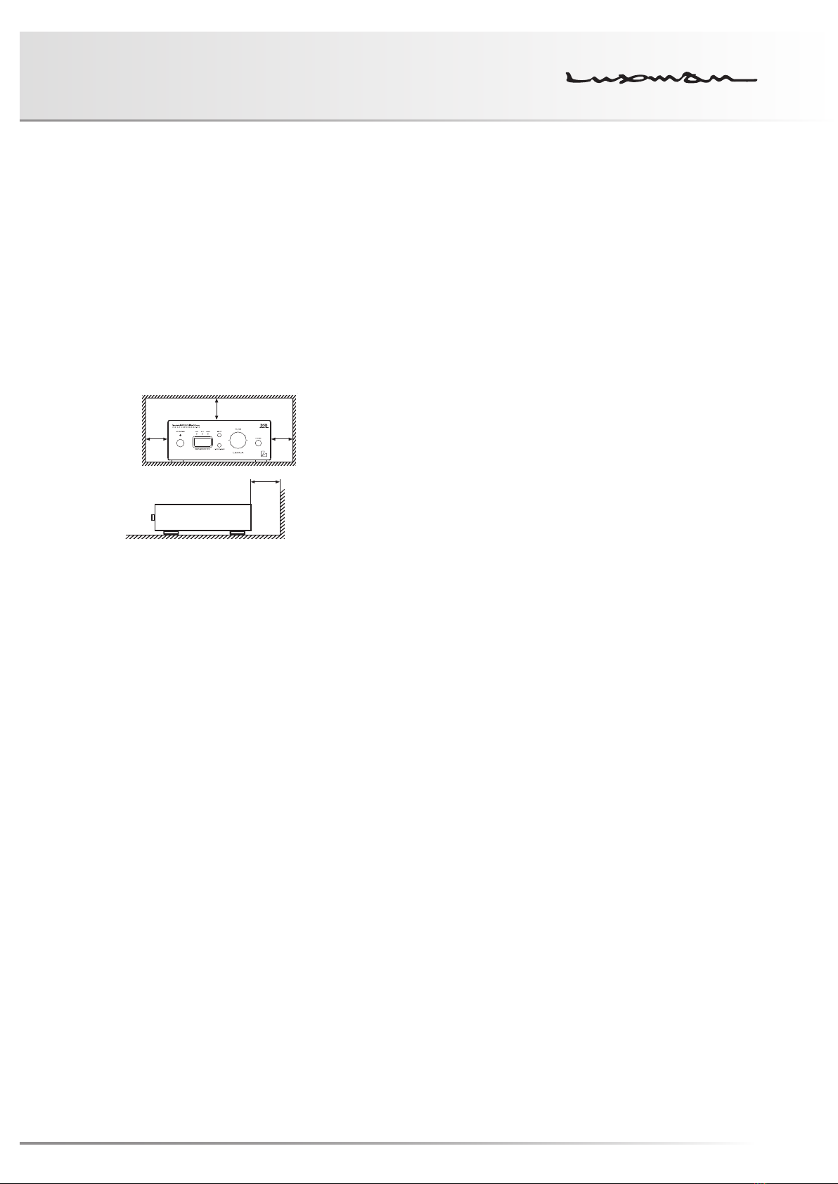
Installation place
Install this unit in a location where good ventilation and heat
radiation are assured.
Especially, the installation of this unit where the direct sun-
light is present, where the temperature rises excessively
high such as close to a heater, or where it is humid or dusty
may cause a malfunction even if heat is efficiently released.
Therefore, do not install this unit in such places.
Note:
For heat dispersal, do not install this equipment in a con-
fined space such as a book case or similar unit.
* Note
Wall
*
* *
Turn off this unit when it is not used.
Depending on the condition of radio waves emitted during
television broadcasting, interference fringes may appear on
the television monitor, but that is not a malfunction. In such
a case, turn off the unit. There may also be a case where
noises are heard on the radio due to radio wave interfer-
ence.
Notice when handling optical digital cables
• Do not fold the cables. For storage, wind each cable to
make a coil whose diameter is approx.15 cm or larger.
• For connection, insert the cable connectors firmly into the
terminals of this unit and the other device.
• Use the cables whose each length is 3 m or less.
• When the cable connectors get dusty, wipe the dust
away with a dry soft cloth before inserting into the termi-
nals.
Cleaning
• Usually, wipe the unit with a dry soft cloth. When the dirt
is hard to remove, dip soft cloth in detergent diluted 5 or
6 times with water, wring it well, and remove contami-
nants. Then, remove the moisture with dry cloth.
• Do not use a solvent like alcohol, benzine, thinner, or
pesticide because such a substance can damage the ex-
terior. In addition, do not let this unit contact a rubber or
plastic form for a long time. That may damage the cabi-
net surface of the unit.
• When using a chemical cloth for cleaning, read the cau-
tion provided with the chemical cloth product.
• Before cleaning, unplug the power cord from the AC out-
let.
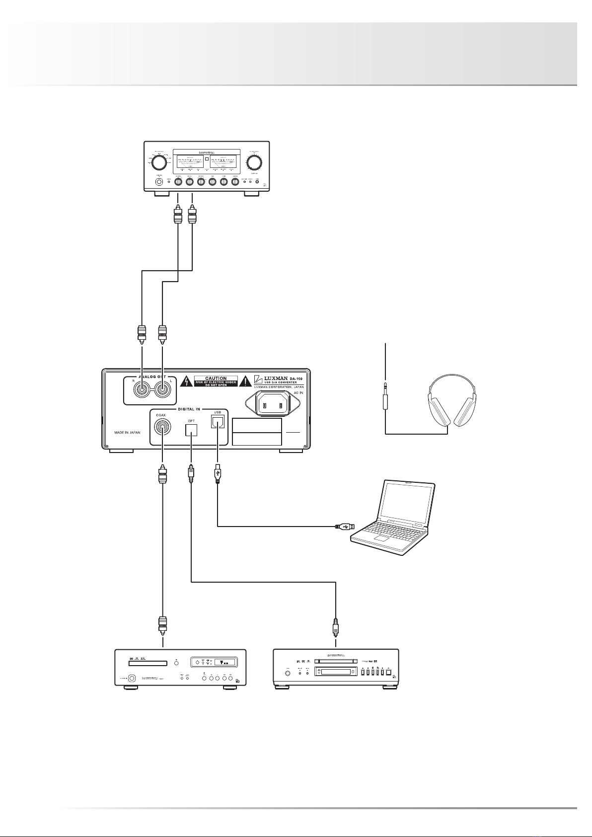
Precautions in connecting with other
components
When connecting this unit to input/output devices other
than a PC/Mac such as a CD player, an SACD player, a
DVD player, and a pre-main amplifier, be sure to turn off
the power of this unit and all other connected devices. Fail-
ure to observe this may generate a strong noise resulting in
speaker damage or cause a malfunction.
The pin-plug to be inserted in each input terminal of this
unit shall be pushed in firmly. If the grounding terminal is
inadequately connected, noises including hum may be gen-
erated, resulting in an adverse S/N ratio.
Protection circuit
This unit is equipped with a protection circuit that is activat-
ed upon the detection of overcurrent to protect the head-
phones. When the protection circuit is activated, the output
to the headphones is shut off and the operation indicator
blinks to show that this unit is in the muting state. When
the cause to activate the protection circuit is eliminated, the
blue operation indicator light comes back on and the op-
erating state resumes. If the protection circuit is frequently
activated, please consult your dealer.
Insertion and extraction of headphone plug
When the headphone (unbalanced) plug is inserted or ex-
tracted, a short circuit occurs between the L ch output and
R ch output because of the structure of the headphone jack
(unbalanced).
If the volume of this unit is turned up at this moment, an
overcurrent flows to the headphone amplifier output and the
overcurrent detection circuit becomes activated, which sets
this unit to the muting state and may also cause a malfunc-
tion. Therefore, the insertion and extraction of the head-
phone plug shall be performed when the volume is turned
down to the minimum or when there is no signal after shut-
ting off input signals.
Repair and adjustment
When repairs or adjustments are needed, please ask the
dealer where you bought the unit.