LXNAV SMARTSHUNT User manual

Page 1 of 112
SMARTSHUNT
Version 0.37
▪Installation manual –Digital Battery Monitoring SmartShunt
▪Installationshandbuch - Digitaler Batterieüberwachungs- SmartShunt
▪Manuel d’installation - SmartShunt surveillance de batterie numérique
▪Manuale d'installazione - SmartShunt digitale di protezione della batteria
▪Manual de instalación - Derivador digital de control de batería
▪Installatie handleiding - Digitale accubewaking SmartShunt
▪Instrukcja instalacji - Cyfrowy bocznik akumulatora
▪Installation s vejledning - Digital batteriovervågning SmartShunt
▪Installationsmanual - Digital batteribevakningsshunt
▪Installasjons handbook - Digital akkumulator overvåknings SmartShunt
▪Asennusopas - Digitaalinen akkumonitori ja shuntti
LXNAV d.o.o. • Kidričeva 24, 3000 Celje, Slovenia • tel +386 592 33 400 fax +386 599 33 522
ENGLISH
8
DEUTCH
17
FRANCAIS
27
ITALIANO
37
ESPAÑOL
47
NEDERLANDS
58
POLSKI
67
DANSK
77
SVENSKA
86
NORSK
95
SUOMEKSI
104

Page 2 of 112
ENGLISH
1Important Notices..................8
1.1 Limited Warranty 8
2Safety .....................................8
2.1 Symbols for warning
indications 8
3General information...............9
4Installation.............................9
4.1 Mounting recommendation 9
4.2 NMEA2000 specifications 9
4.3 Connectors 9
Power supply & battery inputs B1-B39
4.3.1 External temperature sensor
inputs 10
4.3.2 Shunt ...............................10
4.3.3 NMEA2000 compatible M12
connector.....................................10
4.4 LED Indications 11
5Configuring SMARTSHUNT...11
6Configuring via WIFI ...........13
6.1.1 Homepage ........................13
6.1.2 Battery configuration..........13
6.1.3 Shunt configuration page ...13
6.1.4 Info page..........................13
6.2 Configuration via LXNAV
Exxx device 13
6.2.1 Battery setup ....................13
6.2.2 Shunt setup ......................13
7First operation......................13
8Dimensions...........................14
9Wiring...................................15
DEUTSCH
1Wichtige Hinweise .............. 17
1. Eingeschränkte Garantie 17
2Sicherheit ............................ 17
2.1 Symbole für Warnhinweise 17
3Allgemeine Informationen.. 18
4Installation.......................... 18
4.1 Montageempfehlung 18
4.2 NMEA2000 specifications 18
4.3 Verbinder 18
Stromversorgung &; Batterieeingänge
B1-B3...........................................18
4.3.1 Externe Temperatursensor-
Eingänge......................................19
4.3.2 Shunt................................19
4.3.3 NMEA2000-kompatibler M12-
Stecker 19
4.4 LED-Anzeigen 20
5Konfigurierend SMARTSHUNT
20
6Konfiguration über WLAN ... 22
6.1.1 Homepage ........................22
6.1.2 Batteriekonfiguration..........22
6.1.3 Shunt Seite "Konfiguration" 22
6.1.4 Info page..........................22
6.2 Configuration via LXNAV
Exxx device 22
6.2.1 Battery setup.....................22
6.2.2 Shunt setup.......................22
7Erste Inbetriebnahme ......... 22
8Dimensionen ....................... 24
9Verdrahtung ........................ 25

Page 3 of 112
FRANCAIS
1Avis importants ................... 27
1.1 Garantie limitée 27
2Sécurité ............................... 27
2.1 Symboles pour les indications
d'avertissement 27
3Informations générales....... 28
4Installation.......................... 28
4.1.1 Recommendation de montage
28
4.2 Spécifications NMEA2000 28
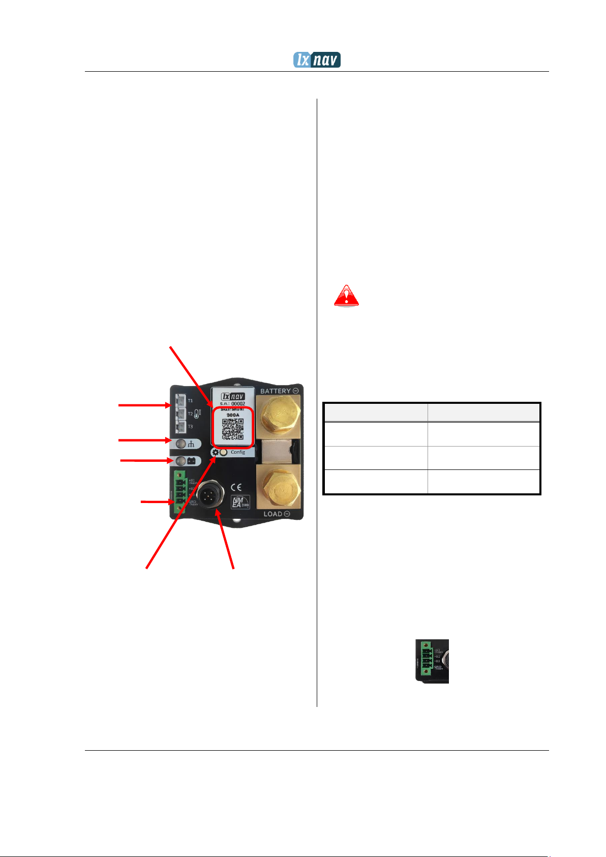
4.3 Connecteurs 28
Alimentation et entrées batterie B1-B3
................................................... 28
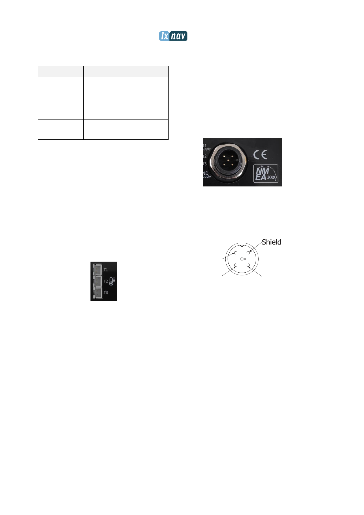
4.3.1 Entrées externes du capteur
de température ............................ 29
4.3.2 Shunt............................... 29
4.3.3 Connecteur M12 compatible
NMEA2000................................... 29
4.4 Indicateurs LED 30
5Configuration du
SMARTSHUNT............................ 30
6Configuration via WIFI........ 32
6.1.1 Page d’acceuil................... 32
6.1.2 Configuration de la batterie 32
6.1.3 Sur cette page, l'utilisateur
configure le type de batterie avec
toutes les données nécessaires qui
sont obligatoires pour des calculs
corrects de l'état et de la santé de la
batterie........................................ 32
6.1.4 Page de configuration du shunt
32
6.1.5 Page d'information ............ 32
6.1.6 Configuration via le
périphérique LXNAV Exxx .............. 32
6.1.7 Configuration de la batterie 32
6.1.8 Configuration du shunt ...... 32
7Première opération ............. 32
8Dimensions.......................... 34
9Câblage................................ 35
ITALIANO
1Avvisi importanti ................. 37
1.1 Garanzia limitata 37
2Sicurezza.............................. 37
2.1 Simboli per le indicazioni di
avvertimento 37
3Generalità ............................ 38
4Installazione........................ 38
4.1 Raccomandazione di
montaggio 38
4.2 Specifiche NMEA2000 38
4.3 Connettori 38
Alimentazione e ingressi batteria B1-B3
................................................... 38
4.3.1 External Ingressi del sensore di
temperatura................................. 39
4.3.2 Shunt ............................... 39
4.3.3 NMEA2000 connettore M12
compatibile .................................. 39
4.4 Indicazioni LED 40
5Configurando SMARTSHUNT40
6Configurazione tramite WIFI
42
6.1.1 Homepage........................ 42
6.1.2 Configurazione della batteria
42
6.1.3 Pagina di configurazione dello
shunt 42
6.1.4 Info page.......................... 42
6.2 Configurazione via LXNAV
Exxx dispositivo 42
6.2.1 Configurazione della batteria
42
6.2.2 Shunt apparecchio............. 42
7Prima operazione................. 42
8Dimensioni........................... 44
9Cablaggio............................. 45

Page 4 of 112
ESPAÑOL
1Avisos importantes ..............47
1.1 Garantía limitada 47
2Seguridad .............................47
2.1 Símbolos para indicaciones
de advertencia 47
1. Entradas de sensor de
temperatura externo .....................48
2.1.1 Shunt ...............................48
2.1.2 NMEA2000 compatible M12
connector.....................................48
3Información general ............49
4Instalación ...........................49
4.1 Recomendación de montaje
49
4.2 NMEA2000 specifications 49
4.3 Connectors 49
Power supply & battery inputs B1-B3
...................................................49
4.3.1 Entradas de sensor de
temperatura externo .....................50
4.3.2 Shunt ...............................50
4.3.3 NMEA2000 compatible M12
connector.....................................50
4.4 Indicaciones LED 51
5Configuración de
SMARTSHUNT ............................51
6Configuración a través de WIFI
53
6.1.1 Homepage ........................53
6.1.2 Battery configuration..........53
6.1.3 Página de configuración de
derivación ....................................53
6.1.4 Página de información........53
6.2 Configuration via LXNAV
Exxx device 53
6.2.1 Configuración de la batería.53
6.2.2 Shunt setup ......................53
7Primera operación................53
8Dimención ............................55
9Alambrado............................56
NEDERLANDS
1Belangrijke mededelingen .. 58
1.1 Beperkte garantie 58
2Veiligheid............................. 58
2.1 Symbolen voor
waarschuwingsindicaties 58
3Algemene informatie........... 59
4Installatie............................ 59
4.1 Montage aanbeveling 59
4.2 NMEA2000 Specificaties 59
4.3 Verbindingslijnen 59
Voeding & batterij-ingangen B1-B3.59
4.3.1 Externe
temperatuursensoringangen...........60
4.3.2 Shunt................................60
4.3.3 NMEA2000 compatibele M12-
connector .....................................60
4.4 LED-indicaties 61
5SMARTSHUNT configureren 61
6Configureren via WIFI ........ 63
6.1 Homepage 63
6.2 Batterij configuratie 63
6.3 Shunt configuratie pagina 63
6.4 Info pagina 63
6.5 Configuratie via LXNAV Exxx-
apparaat 63
6.6 Batterij instellen 63
1. Shunt instellen .......................63
7Eerste operatie.................... 63
8Dimensies............................ 65
9Bedrading ............................ 66

Page 5 of 112
POLSKI
1Ważne uwagi ....................... 67
1.1 Ograniczona gwarancja 67
2Bezpieczeństwo................... 67
2.1 Symbole wskazujące
ostrzeżenia 67
3Informacje ogólne............... 68
4Instalacja ............................ 68
4.1 Zalecenie montażu 68
4.2 NMEA2000 - specyfikacje i
dane techniczne 68
4.3 Złącza 68
Zasilacz i wejścia akumulatorowe B1-
B3............................................... 68
4.3.1 Wejścia zewnętrznych
czujników temperatury.................. 69
4.3.2 Shunt............................... 69
4.3.3 Złącze M12 kompatybilne z
NMEA2000................................... 68
4.4 Wskaźniki LED 70
5Konfiguracja SMARTSHUNT 70
6Konfiguracja przez WIFI ..... 72
6.1 Strona główna 72
6.2 Konfiguracja baterii 72
6.2.1 Strona konfiguracji bocznika72
6.2.2 Strona informacyjna .......... 72
6.2.3 Konfiguracja przez urządzenie
LXNAV Exxx ................................. 72
6.2.4 Konfiguracja baterii ........... 72
6.2.5 Konfiguracja bocznika........ 72
7Pierwsza operacja ............... 72
8Wymiary .............................. 74
9Okablowanie........................ 75
DANSK
1Vigtige meddelelser............. 77
1.1 Begrænset garanti 77
2Sikkerhed............................. 77
2.1 Symboler til
advarselsindikationer 77
3Generelle oplysninger.......... 78
4Installation .......................... 78
4.1 Anbefaling af montering 78
4.2 NMEA2000 specifications 78
4.3 Connectors 78
Strømforsyning og batteriindgange B1-
B3 ............................................... 78
4.3.1 Eksterne
temperaturfølerindgange............... 79
4.3.2 Shunt ............................... 79
4.3.3 NMEA2000-kompatibelt M12-
stik 79
4.4 LED-indikationer 80
5Konfigurere SMARTSHUNT .. 80
6Konfiguration via WIFI........ 82
6.1.1 Homepage........................ 82
6.1.2 Konfiguration af batteri ...... 82
6.1.3 Shunt Konfigurationsside.... 82
6.1.4 Info page.......................... 82
6.2 Konfiguration via LXNAV
Exxx device 82
6.2.1 Battery setup .................... 82
6.2.2 Shunt setup ...................... 82
7Første operation .................. 82
8Dimensioner ........................ 83
9Ledninger............................. 84

Page 6 of 112
SVENSK
1Viktig information ................86
1.1 Begränsad garanti 86
2Säkerhet...............................86
2.1 Symboler för
varningsindikationer 86
3Allmän information ..............87
4Installation...........................87
4.1 Rekommendation för
montering 87
4.2 NMEA2000 Specifikationer 87
4.3 Kontakter 87
Strömförsörjning och batteriingångar
B1-B3...........................................87
4.3.1 Ingångar för extern
temperaturgivare ..........................88
1. Shunt ....................................88
4.3.2 NMEA2000-kompatibel M12-
kontakt 87
4.4 LED-indikationer 89
5Konfigurera SMARTSHUNT ..89
6Konfigurera via WIFI ...........91
6.1 Hemsida 91
6.2 Batteriets konfiguration 91
6.2.1 Shunt configuration page ...91
1. Info sida................................91
6.3 Konfiguration via LXNAV
Exxx device 91
6.3.1 Battery setup ....................91
6.3.2 Shunt setup ......................91
7Första operationen...............91
8Mått......................................92
9Ledningsdragning ................93
NORSK
1Viktige merknader............... 95
1.1 Begrenset garanti 95
2Sikkerhet ............................. 95
2.1 Symboler for
advarselsangivelser 95
3Generell informasjon........... 96
4Installasjon ......................... 96
4.1 Montering anbefaling 96
4.2 NMEA2000 Spesifikasjoner 96
4.3 Connectors 96
Strømforsyning og batteriinnganger
B1-B3...........................................96
4.3.1 Eksterne
temperatursensorinnganger ...........97
4.3.2 Shunt................................97
4.3.3 NMEA2000-kompatibel M12-
kontakt 96
4.4 LED Indications 98
5Konfigurere SMARTSHUNT.. 98
6Konfigurere via WIFI ........ 100
6.1.1 Homepage ......................100
6.1.2 Battery configuration........100
6.1.3 Shunt configuration page..100
6.1.4 Info side .........................100
6.2 Konfigurasjon via LXNAV
Exxx device 100
6.2.1 Battery setup...................100
6.2.2 Shunt setup.....................100
7Første operasjon ............... 100
8Dimensjoner...................... 101
9Ledningsnett ..................... 102

Page 7 of 112
SUOMEKSI
1Tärkeitä huomautuksia ....................................................................... 104
1.1 Rajoitettu takuu 104
2Turvallisuus ......................................................................................... 104
2.1 Varoitusmerkkien symbolit 104
3Yleistä tietoa ....................................................................................... 105
4Asennus ............................................................................................... 105
4.1.1 Asennussuositus....................................................................................... 105
4.2 NMEA2000: n tekniset tiedot 105
4.3 Liittimet 105
Virtalähde ja akkutulot B1-B3 ............................................................................... 105
4.3.1 Ulkoiset lämpötila-anturin tulot.................................................................. 106
4.3.2 Shunt...................................................................................................... 106
4.3.3
NMEA2000-yhteensopiva M12-liitin ............................................................ 106
4.4 LED-merkkivalot 107
5Määrittäminen SMARTSHUNT ............................................................. 107
6Konfigurointi kautta WIFI................................................................... 109
6.1.1 Homepage............................................................................................... 109
6.1.2 Battery konfiguraatio ................................................................................ 109
6.1.3 Shuntin määrityssivu ................................................................................ 109
6.1.4 Info page ................................................................................................ 109
6.2 Konfigurointi kautta LXNAV Exxx device 109
6.2.1 Battery setup........................................................................................... 109
6.2.2 Shunt setup............................................................................................. 109
7Ensimmäinen operaatio....................................................................... 109
8Mitat .................................................................................................... 110
9Johdotus.............................................................................................. 111

ENGLISH
Page 8 of 112
April 2020 © 2020 LXNAV. All rights reserved.
1Important Notices
Information in this document is subject to change
without notice. LXNAV reserves the right to change or
improve their products and to make changes in the
content of this material without obligation to notify any
person or organization of such changes or
improvements.
1.1 Limited Warranty
This digital battery monitoring unit product is
warranted to be free from defects in materials or
workmanship for two years from the date of purchase.
Within this period, LXNAV will, at its sole option, repair
or replace any components that fail in normal use.
Such repairs or replacement will be made at no charge
to the customer for parts and labour, provided that the
customer pays for shipping costs. This warranty does
not cover failures due to abuse, misuse, accident, or
unauthorized alterations or repairs.
THE WARRANTIES AND REMEDIES CONTAINED
HEREIN ARE EXCLUSIVE AND IN LIEU OF ALL OTHER
WARRANTIES EXPRESSED OR IMPLIED OR
STATUTORY, INCLUDING ANY LIABILITY ARISING
UNDER ANY WARRANTY OF MERCHANTABILITY OR
FITNESS FOR A PARTICULAR PURPOSE, STATUTORY
OR OTHERWISE. THIS WARRANTY GIVES YOU
SPECIFIC LEGAL RIGHTS, WHICH MAY VARY FROM
STATE TO STATE.
IN NO EVENT SHALL LXNAV BE LIABLE FOR ANY
INCIDENTAL, SPECIAL, INDIRECT OR
CONSEQUENTIAL DAMAGES, WHETHER RESULTING
FROM THE USE, MISUSE, OR INABILITY TO USE THIS
PRODUCT OR FROM DEFECTS IN THE PRODUCT.
Some states do not allow the exclusion of incidental or
consequential damages, so the above limitations may
not apply to you. LXNAV retains the exclusive right to
repair or replace the unit or software, or to offer a full
refund of the purchase price, at its sole discretion.
SUCH REMEDY SHALL BE YOUR SOLE AND EXCLUSIVE
REMEDY FOR ANY BREACH OF WARRANTY.
To obtain warranty service, contacts your local LXNAV
dealer or contact LXNAV directly.
2Safety
2.1 Symbols for warning indications
The following warning indications are used in this
manual in the context of safety.
Notes with a red triangle indicates that
great potential danger exists that can
lead to serious injury or death. It also
describes procedures which are critical
and may result in loss of data or any
other critical situation.
A Yellow triangle is shown for parts of
the manual which should be read very
carefully and are important when
operating the E500/E700.
A bulb icon is shown when a useful hint
is provided to the reader.
Pass on the safety instructions to other users.
General rules and laws concerning safety and accident
prevention must always be observed.

ENGLISH
Page 9 of 112
3General information
LXNAV SMARTSHUNT is smart battery monitoring unit
compatible with NMEA2000 network standard. It
accurately measures DC voltages of up to three
batteries bounded in series and includes shunt for
current measurements. With additional temperature
sensors for each battery pack, it estimates state of
charge, state of health and remaining time. It supports
multiple types of batteries and can be configured
through any LXNAV Exxx device or via webpage
accessible over internal Wi-Fi hotspot. Parameters set
there are available on NMEA2000 network to any
device such as LXNAV’s E350, E500 etc. LXNAV
SMARTSHUNT is available in three versions with 100,
300 and 500 A shunt. All of them are 25 mV. For proper
installation read next chapters carefully.
QR code for WiFi configuration
NTC sensor
inputs
Status LED
Battery LED
Battery connector
and power supply
N2K connector
Configuration Shunt button
Figure 1: SMARTSHUNT - top view
4Installation
4.1 Mounting recommendation
SMARTSHUNT has flat bottom and should be mounted
with two screws to solid surface next to battery packs
to minimize wire length from battery terminals to
connector on SMARTSHUNT. With this, measurement
error is minimized to minimum.
Do not work on the electrical system
while it is energized.
Do not install the SmartSHUNT near
inflammable substances.
Do not place the SmartSHUNT in a wet,
humid or high temperature
compartments.
Unauthorized modifications exclude
manufacturers' liability for any resulting
damage.
Do not mix batteries of various brands,
voltages or capacities.
4.2 NMEA2000 specifications
Parameter
Description
Compatibility
NMEA2000 compatible
Bit rate
250 kbps
Connection
A coded M12 connector
Table 1: NMEA2000 specifications
4.3 Connectors
Power supply & battery inputs B1-B3
LXNAV SMARTSHUNT is powered from 4-pin terminal
connector from which it also measures voltages of up
to three batteries. Maximum allowable voltage on each
+Bx terminal is 65 V. When installing, try to make
sense wires as short as possible and keep them away
from high current sources like cables, electric motors
etc.
Figure 2: Battery terminals

ENGLISH
Page 10 of 112
Pin name
Description
+B1 (+Supply)
Power supply for device and
measuring port for first battery
+B2
Measuring terminal for second
battery
+B3
Measuring terminal for third
battery
GND (-Supply)
Common ground terminal for all
three batteries, also for power
Supply
Table 2: Battery connector pinout
4.3.1 External temperature sensor inputs
Each external NTC 10 kΩ temperature sensor is
supplied with SMARTSHUNT for additional information
of battery status. With it we can calculate even more
precise capacity of battery that changes with
temperature. Besides that, lifetime of battery also
depends on temperature of environment, where
battery is stored. Sensor is supplied on 1 m long cable
that fits in two pin connectors labeled from T1 to T3.
On the other side of cable is ring lug terminal with
mounting whole diameter of 3.7 mm. When installing
system keep in mind that each sensor number refers
to same battery number. For example, sensor T1 is for
battery pack B1, T2 for B2 and T3 for B3.
Figure 3: NTC sensors inputs T1-T3
4.3.2 Shunt
SMARTSHUNT is low side current sense device and it
must be placed between load and ground. Wire the
terminal labelled BATTERY - to battery ground and
LOAD - to ground from system load. Depends on
power needs use suitable cross sections of cables and
screw them with appropriate ring lugs, that are
compatible with shunt’s screw thread size of M10.
4.3.3 NMEA2000 compatible M12 connector
M12 5-pin A-coded connector on top of unit is
compatible with NMEA2000 and has standard pinout.
When installing, follow the recommendations of
NMEA2000 network wiring. Always use free Tee
connector on existing network. Make sure that
connectors are tightened together properly to seal
metal contacts inside and prevent oxidation.
Figure 4: M12 N2K connector on SMARTSHUNT
Figure 5: NMEA2000 M12 Male connector
pinout (view from unit side)
CAN_L
CAN_H
12V
Ground
NMEA2000 pinout
Male connector (pins)
12V
CAN_L
Ground
Shield
CAN_H
NMEA2000 pinout
Female connector (sockets)
2 1
4
3
5
1 2
3
4
5

ENGLISH
Page 11 of 112
4.4 LED Indications
SMARTSHUNT unit features two RGB LEDs on top side
for quick status indication. One for general status of
unit while the other is for battery state of charge
indication. All possible modes are described in tables
below:
•Status LED:
Colour
Description
Blinking blue LED
with 1 Hz
Working CAN network
Blinking blue LED
with 10 Hz
Initialization of WIFI
network
Solid blue LED
WIFI initialized,
configuration disabled
Solid violet LED
WIFI initialized,
configuration enabled
Blinking red LED
Hardware fault
Table 3: Status LED color description
•Battery LED:
Colour
Description
Blinking red LED 1
Hz
SMARTSHUNT is not
configured
Solid red LED
State of charge <30 %
Solid yellow LED
State of charge <50 %
Solid green LED
State of charge >50 %
Table 4: Battery LED color description
5Configuring
SMARTSHUNT
For proper operation SMARTSHUNT must be
configured prior use. Configuration can be performed
via WiFi connection or NMEA2000 network with one of
LXNAV devices.
There are several parameters that should be either
selected from available options or written by the user.
Selecting right parameters is crucial for correct
calculations and displaying warnings.
Battery
parameter
Options
Bank type
Main battery, primary
battery, secondary battery,
auxiliary battery, port
battery, starboard battery,
bow battery, stern battery,
solar battery, starter
battery, battery bank 1,
battery bank 2 and “other”
battery
Chemistry type
Lead Acid, Li-Ion, Ni-Cad,
Zn-O, Ni-Mh
Battery type
Flooded, GEL, AGM
Nominal voltage
6 V, 12 V, 24 V, 32 V, 36 V,
42 V, 48 V
Rated capacity
Should be set by the user
according to battery
capacity
Temperature
Celsius, Fahrenheit, Kelvin
Table 6: Battery parameters

ENGLISH
Page 12 of 112
Shunt
parameter
Options
Peukert
exponent
Dependency between battery
capacity and discharge rate.
Valid values 1.0 ~ 1.5 Initial
value is set automatically based
on battery chemistry.
Charging
efficiency
Charger’s efficiency. Valid
values 0.6 ~ 1.0 Value is
constantly modified during
battery lifetime.
Temperature
coefficient
Dependency between battery
capacity and environment
temperature. Valid values 0.0
~ 1.0
Voltage at
battery full (V)
Charger’s float voltage. Initial
value is set automatically
based on battery chemistry
and nominal voltage.
Current at
battery full (A)
Charger’s float current. Initial
value is set automatically
based on battery chemistry
and rated capacity.
Voltage at
battery empty
(V)
Battery empty voltage. Initial
value is set automatically
based on battery chemistry
and nominal voltage.
Config button
action
No action: WiFi is always on
and ready for configuration;
WiFi power: button press
enables or disables WiFi.
When enabled, it gets
automatically in config mode;
WiFi config: WiFi is enabled all
the time, with pressing button
SMARTSHUNT enters, or exit,
config mode;
SoC low limit
(%)
0, 5, 10, 15, 20, 25, 30, 35,
40, 45, 50, 55, 60
Table 5: Shunt parameters
Alert parameters:
Parameter values in this menu can be freely selected
by the user. When measurements are outside limited
values, warning message will be sent to NMEA2000
network and shown on screen of Exxx device. List of
available alerts is written bellow:
Alert parameter
Options
Low voltage
Alert will show up when
voltage on battery will be
bellow selected value
High voltage
Alert will show up when
voltage on battery will be
above selected value
High charge current
Set the maximum
charging current
High discharge
current
Set upper limit of current
that can be drawn by
devices
Low temperature
Set low temperature limit
for alert
High temperature
Set high temperature limit
for alert
Low state of charge
Set when to alert battery
remaining capacity
Table 7: Alarm parameter
Press ‘’SAVE’’ to keep your settings.

ENGLISH
Page 13 of 112
6Configuring via WIFI
SMARTSHUNT has integrated WIFI hot spot to which
you can connect with smart phone or any other device
that allows web browsing. It can be automatically
connected with scanning QR code bellow serial
number. You may get a message from the system, that
there may not be available internet connection but just
simply run your web browser and type in
config.lxnav.com. With pressing enter, configuration
page will show up. Before changing any parameter,
user should put SMARTSHUNT in config mode. That
means violet status LED must be lit. In any other mode,
settings will not be saved. For enabling WIFI or putting
it in config mode press Config button for more than a
second.
Configuration webpage that will show up consist of
four pages easily selectable on top of the screen:
Home, Battery config, Shunt config and Info page.
6.1.1 Homepage
On home page user can view all current data of system
in real time that are result of selected values on config
pages, for example voltages, temperatures, current
drawn, state of charge etc. as well as peak recorded
values and history of alarm messages.
6.1.2 Battery configuration
On this page user configures battery type with all
necessary data that are mandatory for correct
calculations of battery state and health.
Please do not access to the browser via QR
code for configuration, because browser does
not support popup windows and saving
configuration will not be possible.
The only way is to open browser and visit
config.lxnav.com. Then you can change and save
configuration settings.
6.1.3 Shunt configuration page
All the necessary data related to current
measurements should be filled out in this page. There
is also button setting for desired WIFI action.
6.1.4 Info page
On this page are all information about device. Its serial
number, hardware and software version.
6.2 Configuration via LXNAV Exxx device
Second option for configuration of SMARTSHUNT is via
any Exxx device. Assuming that the NMEA2000
network is established battery and shunt configuration
pages are accessible under different paths under
setting menus. In following two chapters are written
paths where menus can be found and their window
previews. For operating and calibrating external
devices on Exxx units refer also to Exxx user manual.
6.2.1 Battery setup
Parameters related to battery packs should be set in
menu that is accessible under this path:
Settings->Network->Device calibration->Battery
6.2.2 Shunt setup
Second configuration menu is found under:
Settings->Network->Connected devices->
Device details->Device setup
Parameters there relates to measurements between
shunt’s terminals. There is also information about WiFi
hotspot name and password under which is
SMARTSHUNT accessible.
Inside shunt setup is submenu Alerts configuration
with user selectable parameters limits for warning
messages. There are seven warnings available in total.
7First operation
SmartShunt will start to operate normally and indicate
real values after initial cycle. Initial cycle is finished,
when first time are fulfilled conditions for battery full
(Voltage must be higher than voltage setting for full
and charge current must drop below full current
setting)
To get really good performance, smart shunt will need
more charge/discharge cycles, to tune also other
parameters like charge efficiency….

ENGLISH
Page 14 of 112
8Dimensions
Drawing is not to scale

ENGLISH
Page 15 of 112
9Wiring
Figure bellow shows example wiring with combination of three battery packs. In case user has less batteries, leave
dedicated terminals empty.
Figure 6: Batteries in series
Figure 7: Batteries in parallel

ENGLISH
Page 16 of 112
Figure 8: Wiring diagram for 3S Battery (e.g. 36V)
Figure 9: Wiring diagram for 2S Battery (e.g. 24V)
Figure 10: Wiring diagram for 1S Battery (e.g., 12V)

DEUTSCH
Page 17 of 112
1Wichtige Hinweise
Die Informationen in diesem Dokument können ohne
vorherige Ankündigung geändert werden. LXNAV
behält sich das Recht vor, seine Produkte zu ändern
oder zu verbessern und Änderungen am Inhalt dieses
Materials vorzunehmen, ohne verpflichtet zu sein, eine
Person oder Organisation über solche Änderungen
oder Verbesserungen zu informieren.
1. Eingeschränkte Garantie
Für dieses digitale Batterieüberwachungsgerät gilt eine
Garantie von zwei Jahren ab Kaufdatum, dass es frei
von Material- oder Verarbeitungsfehlern ist. Innerhalb
dieses Zeitraums wird LXNAV nach eigenem Ermessen
alle Komponenten reparieren oder ersetzen, die bei
normalem Gebrauch ausfallen. Solche Reparaturen
oder Ersatzlieferungen werden dem Kunden kostenlos
für Teile und Arbeit berechnet, sofern der Kunde die
Versandkosten trägt. Diese Garantie deckt keine
Ausfälle ab, die auf Missbrauch, Missbrauch, Unfall
oder nicht autorisierte Änderungen oder Reparaturen
zurückzuführen sind.
DIE HIERIN ENTHALTENEN GARANTIEN UND
RECHTSMITTEL SIND AUSSCHLIESSLICH UND
ERSETZEN ALLE ANDEREN AUSDRÜCKLICHEN ODER
STILLSCHWEIGENDEN ODER GESETZLICHEN
GARANTIEN, EINSCHLIESSLICH JEGLICHER
HAFTUNG, DIE SICH AUS EINER GARANTIE DER
MARKTGÄNGIGKEIT ODER EIGNUNG FÜR EINEN
BESTIMMTEN ZWECK, GESETZLICH ODER
ANDERWEITIG, ERGIBT. DIESE GARANTIE GEWÄHRT
IHNEN BESTIMMTE GESETZLICHE RECHTE, DIE VON
STAAT ZU STAAT UNTERSCHIEDLICH SEIN KÖNNEN.
IN KEINEM FALL HAFTET LXNAV FÜR ZUFÄLLIGE,
SPEZIELLE, INDIREKTE ODER FOLGESCHÄDEN,
UNABHÄNGIG DAVON, OB SIE SICH AUS DER
VERWENDUNG, DEM MISSBRAUCH ODER DER
UNFÄHIGKEIT, DIESES PRODUKT ZU VERWENDEN,
ODER AUS MÄNGELN DES PRODUKTS ERGEBEN.
In einigen Staaten ist der Ausschluss von Neben- oder
Folgeschäden nicht zulässig, so dass die oben
genannten Einschränkungen möglicherweise nicht auf
Sie zutreffen. LXNAV behält sich das ausschließliche
Recht vor, das Gerät oder die Software nach eigenem
Ermessen zu reparieren oder zu ersetzen oder eine
vollständige Rückerstattung des Kaufpreises
anzubieten. EIN SOLCHER RECHTSBEHELF IST IHR
EINZIGER UND AUSSCHLIESSLICHER RECHTSBEHELF
BEI EINER VERLETZUNG DER GARANTIE.
Um Garantieleistungen in Anspruch zu nehmen,
wenden Sie sich an Ihren LXNAV-Händler vor Ort oder
wenden Sie sich direkt an LXNAV.
2Sicherheit
2.1 Symbole für Warnhinweise
Die folgenden Warnhinweise werden in diesem
Handbuch im Zusammenhang mit der Sicherheit
verwendet.
Notizen mit einem roten Dreieck weisen
darauf hin, dass ein großes
Gefahrenpotenzial besteht, das zu
schweren Verletzungen oder zum Tod
führen kann. Es beschreibt auch
Verfahren, die kritisch sind und zu
Datenverlusten oder anderen kritischen
Situationen führen können.
Ein gelbes Dreieck markiert Teile der
Bedienungsanleitung, die man sehr gut
lesen sollte und die wichtig bei der
Bedienung des E500/E700 sind.
Ein Glühbirnensymbol wird angezeigt,
wenn dem Leser ein nützlicher Hinweis
gegeben wird.
Geben Sie die Sicherheitshinweise an andere Benutzer
weiter.
Allgemeine Regeln und Gesetze zur Sicherheit und
Unfallverhütung sind stets zu beachten.

DEUTSCH
Page 18 of 112
3Allgemeine
Informationen
LXNAV SMARTSHUNT ist eine intelligente
Batterieüberwachungseinheit, die mit dem NMEA2000-
Netzwerkstandard kompatibel ist. Es misst präzise
Gleichspannungen von bis zu drei in Reihe
geschalteten Batterien und verfügt über einen Shunt
für Strommessungen. Mit zusätzlichen
Temperatursensoren für jeden Akkupack schätzt er
den Ladezustand, den Gesundheitszustand und die
verbleibende Zeit. Es unterstützt mehrere
Batterietypen und kann über jedes LXNAV Exxx-Gerät
oder über eine Webseite konfiguriert werden, auf die
über einen internen Wi-Fi-Hotspot zugegriffen werden
kann. Die dort eingestellten Parameter sind im
NMEA2000-Netzwerk für jedes Gerät wie E350, E500
usw. von LXNAV verfügbar. LXNAV SMARTSHUNT ist in
drei Versionen mit 100, 300 und 500 A Shunt erhältlich.
Alle haben eine Spannung von 25 mV. Für eine
ordnungsgemäße Installation lesen Sie die nächsten
Kapitel sorgfältig durch.
QR-Code für WLAN-Konfiguration
NTC sensor
inputs
Status LED
Battery LED
Battery connector
and power supply
N2K connector
Configuration Shunt button
Figure 11: SMARTSHUNT - top view
4Installation
4.1 Montageempfehlung
SMARTSHUNT hat einen flachen Boden und sollte mit
zwei Schrauben auf fester Oberfläche neben
Batteriepacks montiert werden, um die Kabellänge von
den Batteriepolen zum Stecker am SMARTSHUNT zu
minimieren. Damit wird der Messfehler auf ein
Minimum minimiert.
Arbeiten Sie nicht an der elektrischen
Anlage, während sie unter Spannung
steht.
Installieren Sie den SmartSHUNT nicht in
der Nähe von brennbaren Stoffen.
Platzieren Sie den SmartSHUNT nicht in
nassen, feuchten oder
Hochtemperaturkammern.
Eigenmächtige Änderungen schließen die
Haftung des Herstellers für daraus
resultierende Schäden aus.
Mischen Sie keine Batterien
verschiedener Marken, Spannungen oder
Kapazitäten.
4.2 NMEA2000 specifications
Parameter
Beschreibung
Kompatibilität
NMEA2000-kompatibel
Bitfrequenz
250 kbps
Verbindung
Ein codiertes M12
Verbinder
Tabelle 8: NMEA2000-Spezifikationen
4.3 Verbinder
Stromversorgung &; Batterieeingänge B1-B3
LXNAV SMARTSHUNT wird über einen 4-poligen
Klemmenstecker mit Strom versorgt, von dem aus er
auch Spannungen von bis zu drei Batterien misst. Die
maximal zulässige Spannung an jeder +Bx-Klemme
beträgt 65 V. Versuchen Sie bei der Installation,
sinnvolle Drähte so kurz wie möglich zu halten und
halten Sie sie von Hochstromquellen wie Kabeln,
Elektromotoren usw. fern.
Figure 12: Battery terminals

DEUTSCH
Page 19 of 112
Pin name
Beschreibung
+B1 (+Supply)
Stromversorgung für Gerät und
Messanschluss für erste Batterie
+B2
Messklemme für Zweitbatterie
+B3
Messklemme für dritte Batterie
GND (-Supply)
Gemeinsame Masseklemme für
alle drei Batterien, auch für die
Stromversorgung
Versorgung
Table 9: Battery connector pinout
4.3.1 Externe Temperatursensor-Eingänge
Jeder externe NTC 10 kΩ Temperatursensor wird mit
SMARTSHUNT für zusätzliche Informationen über den
Batteriestatus geliefert. Damit können wir die Kapazität
der Batterie, die sich mit der Temperatur ändert, noch
genauer berechnen. Außerdem hängt die Lebensdauer der
Batterie auch von der Temperatur der Umgebung ab, in
der die Batterie gelagert wird. Der Sensor wird mit einem
1 m langen Kabel geliefert, das in zwei Pin-Steckverbinder
passt, die von T1 bis T3 beschriftet sind. Auf der anderen
Seite des Kabels befindet sich eine Ringschuhklemme mit
einem Montagedurchmesser von 3,7 mm. Beachten Sie bei
der Installation des Systems, dass sich jede
Sensornummer auf dieselbe Batterienummer bezieht. Zum
Beispiel ist Sensor T1 für Akkupack B1, T2 für B2 und T3
für B3.
Figure 13: NTC sensors inputs T1-T3
4.3.2 Shunt
SMARTSHUNT ist ein Low-Side-Strommessgerät und muss
zwischen Last und Masse platziert werden. Verdrahten Sie
die Klemme mit der Bezeichnung BATTERY - mit
Batteriemasse und LOAD - mit Masse von der Systemlast.
Je nach Leistungsbedarf geeignete Kabelquerschnitte
verwenden und diese mit entsprechenden Ringfahnen
verschrauben, die mit der Gewindegröße M10 des Shunts
kompatibel sind.
4.3.3 NMEA2000-kompatibler M12-
Stecker
Der 5-polige M12-A-kodierte Stecker auf der
Oberseite des Geräts ist mit NMEA2000 kompatibel
und verfügt über eine Standard-Pinbelegung.
Befolgen Sie bei der Installation die Empfehlungen
der NMEA2000-Netzwerkverkabelung. Verwenden
Sie immer den freien T-Shirt-Anschluss im
vorhandenen Netzwerk. Stellen Sie sicher, dass die
Steckverbinder richtig angezogen sind, um
Metallkontakte im Inneren abzudichten und
Oxidation zu verhindern.
Figure 14: M12 N2K Steckverbinder auf
SMARTSHUNT
Figure 15: NMEA2000 M12 Stecker
Pinbelegung (Ansicht von der Geräteseite)
CAN_L
CAN_H
12V
Ground
NMEA2000 pinout
Male connector (pins)
12V
CAN_L
Ground
Shield
CAN_H
NMEA2000 pinout
Female connector (sockets)
2 1
4
3
5
1 2
3
4
5

DEUTSCH
Page 20 of 112
4.4 LED-Anzeigen
Die SMARTSHUNT-Einheit verfügt über zwei RGB-LEDs auf
der Oberseite für eine schnelle Statusanzeige. Eine für den
allgemeinen Status des Geräts, während die andere für die
Anzeige des Ladezustands der Batterie vorgesehen ist. Alle
möglichen Modi sind in den folgenden Tabellen
beschrieben:
1. Status-LED:
Farbe
Beschreibung
Blau blinkende LED
mit 1 Hz
Funktionierendes CAN-
Netzwerk
Blau blinkende LED
mit 10 Hz
Initialization of WIFI network
Durchgehend blaue
LED
WLAN initialisiert,
Konfiguration deaktiviert
Durchgehend violette
LED
WLAN initialisiert,
Konfiguration aktiviert
Blinking red LED
Hardware-Fehler
Table 10: Farbbeschreibung der Status-LED
1. Batterie-LED:
Farbe
Beschreibung
Blinking red LED 1
Hz
SMARTSHUNT is not
configured
Solid red LED
State of charge <30 %
Solid yellow LED
State of charge <50 %
Solid green LED
State of charge >50 %
Table 11: Farbbeschreibung der Batterie-LED
5Konfigurierend
SMARTSHUNT
Für einen ordnungsgemäßen Betrieb muss
SMARTSHUNT vor der Verwendung konfiguriert
werden. Die Konfiguration kann über eine WLAN-
Verbindung oder ein NMEA2000-Netzwerk mit
einem der LXNAV-Geräte erfolgen.
Es gibt mehrere Parameter, die entweder aus den
verfügbaren Optionen ausgewählt oder vom
Benutzer geschrieben werden sollten.
Die Auswahl der richtigen Parameter ist
entscheidend für korrekte Berechnungen und die
Anzeige von Warnungen.
Batterie-
Parameter
Optionen
Art der Bank
Hauptbatterie,
Primärbatterie,
Sekundärbatterie,
Zusatzbatterie,
Backbordbatterie,
Steuerbordbatterie,
Bugbatterie,
Heckbatterie,
Solarbatterie,
Starterbatterie,
Batteriebank 1,
Batteriebank 2 und
"andere" Batterie
Art der Chemie
Lead Acid, Li-Ion, Ni-Cad,
Zn-O, Ni-Mh
Batterietyp
Flooded, GEL, AGM
Nennspannung
6 V, 12 V, 24 V, 32 V, 36
V, 42 V, 48 V
Nennkapazität
Sollte vom Benutzer
entsprechend der
Batteriekapazität
eingestellt werden
Temperature
Celsius, Fahrenheit,
Kelvin
Table 13: Battery parameters
Table of contents
Languages:
Other LXNAV Marine Equipment manuals
Popular Marine Equipment manuals by other brands

TradeQuip
TradeQuip PORTA POWER KIT owner's manual

AUTOHELM
AUTOHELM Maxiview ST80 user manual

Simpson Lawrence
Simpson Lawrence Horizon 500 Owners installation, operation & servicing manual

Eaton
Eaton Crouse-hinds series Technical manual

Pyronix
Pyronix DELTABELL-WE installation guide

Wet Sounds
Wet Sounds XS-808 owner's manual

Ros
Ros PT-10 Operating and maintenance manual

INIM Electronics
INIM Electronics IVY series Installation and programming manual

Onwa
Onwa KEC-30 Operator's manual

Dual
Dual MD200 Installation & owner's manual

Furuno
Furuno FELCOM 12 installation manual

Boss Audio Systems
Boss Audio Systems MR1308UAB user manual