E2S Warning Signals Impress House, Mansell Road, Acton, London W3 7QH
[email protected] e2s.com
Page 1 of 1
D221-95-001-IS_Issue_A - 09/03/2021
1000Hz PFEER Toxic Gas
1200/500Hz @ 1Hz DIN /PFEER P.T.A.P.
1000Hz @ 0.5Hz(1s on, 1soff) PFEER Gen. Alarm
1.4KHz-1.6KHz 1s, 1.6KHz-1.4KHz 0.5s NF C 48-265
544Hz(100mS)/440Hz (400mS) NF S 32-001
1500/500Hz - (0.5s on , 0.5s off) x3 + 1s gap AS4428
500-1500Hz Sweeping 2 sec on 1 sec off AS4428
500/1200Hz @ 0.26Hz (3.3son, 0.5s off) Netherlands -
NEN 2575
1000Hz (1s on, 1s off)x7 + (7s on, 1s off) IMO Code 1a
1000Hz (1s on, 1s off)x7 + (7s on, 1s off) IMO Code 1a
420Hz(0.5s on, 0.5s off)x3 + 1s gap ISO 8201 Temporal
Pattern
1000Hz(0.5s on, 0.5s off)x3 + 1s gap ISO 8201 Temporal
Pattern
422/775Hz - (0.85 on, 0.5 off) x3 + 1s gap NFPA -
Temporal Coded
1000/2000Hz @ 1Hz Singapore
300Hz Continuous
440Hz Continuous
470Hz Continuous
500Hz Continuous IMO code 2 (Low)
554Hz Continuous
660Hz Continuous
800Hz IMO code 2 (High)
1200Hz Continuous
2000Hz Continuous
2400Hz Continuous
440Hz @0.83Hz (50
cycles/minute) Intermittent
470Hz @0.9Hz - 1.1s Intermittent
470Hz @5Hz - (5
cycles/second) Intermittent
544Hz @ 1.14Hz - 0.875s Intermittent
655Hz @ 0.875Hz Intermittent
660Hz @0.28Hz - 1.8sec
on, 1.8sec off Intermittent
660Hz @3.34Hz - 150mS
on, 150mS off Intermittent
745Hz @ 1Hz Intermittent
800Hz - 0.25sec on, 1 sec off Intermittent
800Hz @ 2Hz IMO code 3.a
(High) Intermittent
1000Hz @ 1Hz Intermittent
2400Hz @ 1Hz Intermittent
2900Hz @ 5Hz Intermittent
363/518Hz @ 1Hz Alternating
450/500Hz @ 2Hz Alternating
554/440Hz @ 1Hz Alternating
554/440Hz @ 0.625Hz Alternating
561/760Hz @0.83Hz (50
cycles/minute) Alternating
800/1000Hz @ 0.875Hz Alternating
2400/2900Hz @ 2Hz Alternating
500/1200Hz @ 0.3Hz Sweeping
560/1055Hz @ 0.18Hz Sweeping
560/1055Hz @ 3.3Hz Sweeping
660/1200Hz @ 1Hz Sweeping
800/1000Hz @ 1Hz Sweeping
800/1000Hz @ 7Hz Sweeping
800/1000Hz @ 50Hz Sweeping
2400/2900Hz @ 7Hz Sweeping
2400/2900Hz @ 1Hz Sweeping
2400/2900Hz @ 50Hz Sweeping
2500/3000Hz @ 2Hz Sweeping
2500/3000Hz @ 7.7Hz Sweeping
800Hz Motor Siren
1200Hz Motor Siren
2400Hz Motor Siren
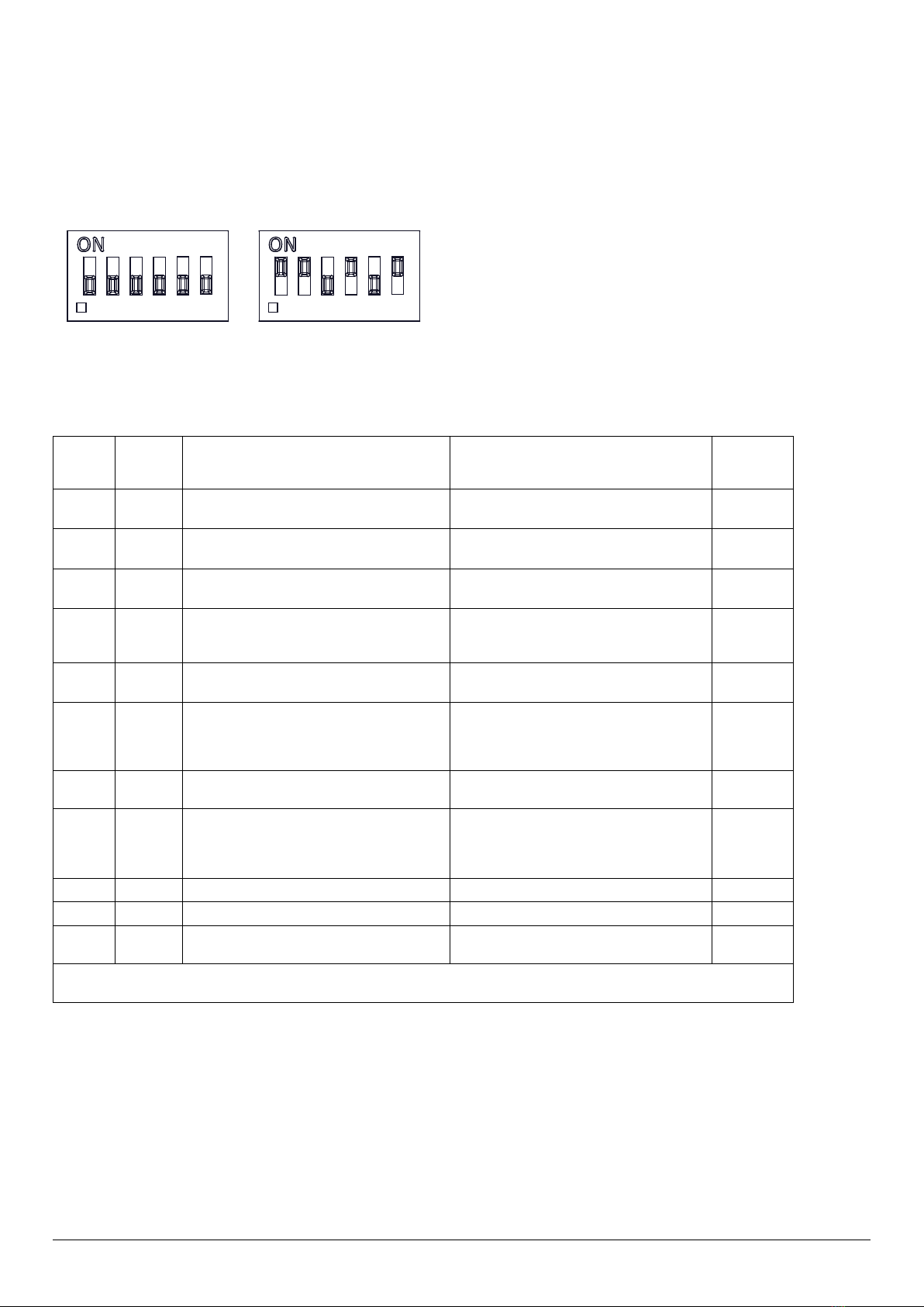
Stage 1
Set DIP
SW 1
Tone No.
Tone Description Tone Visual
Stage 1 & 2
DIP SW 1/2
Settings
1 2 3 4 5 6
Stage 3
Set DIP
SW 1
(S3)
Stage 4
Set DIP
SW 1
(S2 + S3)
0 0 0 0 0 0
1
2
3
4
5
6
7
8
9
10
11
12
13
14
15
16
17
18
19
20
21
22
23
24
25
26
27
28
29
30
31
32
33
34
35
36
37
38
39
40
41
46
47
48
49
50
52
53
54
55
56
57
58
59
60
61
62
63
42
1 0 0 0 0 0
0 1 0 0 0 0
1 1 0 0 0 0
0 0 1 0 0 0
1 0 1 0 0 0
0 1 1 0 0 0
1 1 1 0 0 0
0 0 0 1 0 0
1 0 0 1 0 0
0 1 0 1 0 0
1 1 0 1 0 0
0 0 1 1 0 0
1 0 1 1 0 0
0 1 1 1 0 0
1 1 1 1 0 0
0 0 0 0 1 0
1 0 0 0 1 0
0 1 0 0 1 0
1 1 0 0 1 0
0 0 1 0 1 0
1 0 1 0 1 0
0 1 1 0 1 0
1 1 1 0 1 0
1 1 0 1 1 0
0 0 1 1 1 0
0 1 1 1 1 0
0 0 0 0 0 1
0 1 0 0 0 1
1 1 0 0 0 1
0 0 1 0 0 1
1 0 1 0 0 1
0 1 1 0 0 1
1 1 1 0 0 1
0 0 0 1 0 1
0 1 0 1 0 1
1 0 1 1 0 1
0 1 1 1 0 1
1 1 1 1 0 1
0 0 0 0 1 1
1 0 0 0 1 1
0 1 0 0 1 1
1 1 0 0 1 1
0 0 1 0 1 1
1 0 1 0 1 1
0 1 1 0 1 1
1 1 1 0 1 1
0 0 0 1 1 1
1 0 0 1 1 1
0 1 0 1 1 1
1 1 0 1 1 1
0 0 1 1 1 1
1 0 1 1 1 1
0 1 1 1 1 1
0 0 0 1 1 0
1 0 0 1 1 0
0 1 0 1 1 0
1 1 1 1 1 0
1 0 0 0 0 1
1 0 0 1 0 1
1 0 1 1 1 0
1000Hz
1200Hz
500Hz 1s
1000Hz 1s
1s
1600Hz
1400Hz 1s
0.5s
544Hz 0.1s
0.4s
440Hz
0.5s
1500Hz
500Hz 0.5s 0.5s 0.5s 0.5s 1s
2s 1s
3s 0.5s
1500Hz
500Hz
1200Hz
500Hz
1000Hz
1s
1s
1s
1s
1s
1s
1s
1s
1s
1s
1s
1s
1s
1s
7s
7s
420Hz 0.5s
0.5s
0.5s
0.5s
0.5s
1s
1000Hz 0.5s
0.5s
0.5s
0.5s
0.5s
1s
1200Hz
500Hz 0.85 0.5s 0.85 0.5s 0.85
2000Hz
1000Hz
1s
f(Hz)
a(s)
b(s)
(f=440, a=0.6, b=0.6)
(f=470, a=0.55, b=0.55)
(f=470, a=0.1, b=0.1)
(f=470, a=0.43, b=0.44)
(f=655, a=0.57, b=0.57)
(f=660, a=1.8, b=1.8)
(f=660, a=0.15, b=0.15)
(f=745, a=0.5, b=0.5)
(f=800, a=0.25, b=1)
(f=800, a=0.25, b=0.25)
(f=1000, a=0.5, b=0.5)
(f=2400, a=0.5, b=0.5)
(f=2900, a=0.1, b=0.1)
f1(Hz)
a(s)
f(Hz)
f1(Hz)
a(s) a(s)
f(Hz)
(f=363, f1=518, a=0.1)
(f=450, f1=500, a=0.25)
(f=440, f1=554, a=0.5)
(f=440, f1=554, a=0.8)
(f=561, f1=760, a=0.6)
0 0 1 1 0 1
1 1 0 1 0 1
43
44
45
780/600Hz @ 0.96Hz Alternating
800/1000Hz @ 2Hz Alternating
970/800Hz @ 2Hz Alternating
64 Simulated Bell 1 1 1 1 1 1
f1(Hz)
a(s) a(s)
f(Hz)
(f=800, f1=1000, a=0.57)
(f=2400, f1=2900, a=0.25)
f1(Hz)
a(s) a(s)
f(Hz)
(f=800, f1=1000, a=0.25)
f1(Hz) a(s) a(s)
f(Hz)
(f=600, f1=780, a=0.52)
f1(Hz) a(s) a(s)
f(Hz)
(f=800, f1=970, a=0.25)
(f=500, f1=1200, a=3.34)
(f=560, f1=1055, a=5.47)
(f=560, f1=1055, a=0.3)
f1(Hz)
a(s)
f(Hz)
51 600/1250Hz @ 0.125Hz Sweeping (f=600, f1=1250, a=8)
f(Hz)
a(s)
(f=800, a=1.6)
(f=1200, a=2)
(f=2400, a=1.7)
1450Hz 0.25s
0.69ms
(f=660, f1=1200, a=1)
(f=800, f1=1000, a=1)
(f=800, f1=1000, a=0.14)
(f=800, f1=1000, a=0.02)
(f=2400, f1=2900, a=0.14)
(f=2400, f1=2900, a=1)
(f=2400, f1=2900, a=0.02)
(f=2500, f1=3000, a=0.5)
(f=2500, f1=3000, a=0.13)
(f=300)
(f=440)
(f=470)
(f=500)
(f=554)
(f=660)
(f=800)
(f=1200)
(f=2000)
(f=2400)
f(Hz)
0.5s
2
3
2
24
19
44
44
24
34
34
1
1
1
3
44
44
44
24
24
24
24
24
24
24
24
24
24
8
8
24
8
24
24
24
24
24
24
24
24
24
24
24
24
24
24
24
24
24
8
8
24
8
21
24
24
24
24
24
24
24
24
24
3
20
44
44
44
1
1
1
1
35
1
1
8
8
8
35
8
8
8
8
8
8
8
8
8
19
19
19
19
19
19
19
19
19
19
19
19
19
19
12
12
12
12
12
12
12
12
12
12
12
12
12
12
12
12
1
1
8
8
8
35
35
35
35
35
f1(Hz)
a(s)
f(Hz)