philippi VTM User manual

Tank-Monitor VTM
philippi elektrische systeme gmbh www. philippi-online.de
D-71686 Remseck am Neckar Tel: +49 (0)7146/8744-0,Fax-22
OPERATING MANUAL
Tank Monitor VTM
Thank you for buying the Tank Monitor VTM. This digital unit is state of the art in
Tank monitoring.
On the large, illuminated display you can read:
•the voltage of up to 2 additional batteries
•the current filling levels of up to 4 tanks and have the opportunity: -
You recognize at a glance:
• to set an alarm threshold for each tank (full or empty alarm)
• to set an alarm threshold for each voltage (low and high level alarm)

Tank-Monitor VTM
REV 1A –FEB 2020 - Software Version 1.0 page 2
1 General Information
1.1 Purpose
The tank monitor VTM can only be operated with low voltage DC 8-32V.It is designed for use on
yachts and may only be operated in closed rooms that are protected from rain, humidity, dust and
condensation. Never use the tank monitor in places where there is a risk of explosion due to gas or
dust. The tank monitor is not suitable for outdoor installation.
1.2 Scope of delivery
•Tank Monitor VTM
• 3 Plug-in terminals (MVSTB 2,5- 2- and 3-and 9-pole)
•2 fuse holder ASH1 incl. fuse FSS 1A
•This operating manual
1.3. Recommended sensors (to be ordered separately)
To measure the fluid level, we recommend the immersion tube sensors of the TGT or TGW series for
fuel and fresh water as well as the ultrasonic sensors UTV for waste holding tanks and the flow rate
sensor DFS (fresh water only). Please use for deeper tanks up to 200 cm and very precise
measurements the pressure sensor TDS200 (water/diesel/grey/black water) or TDN200 (water).
However, these sensors are not included in the scope of delivery.
Sensors from other manufacturers can also be connected.
The Monitor is configured In SETUP to the connected sensors. It is also possible to adapt it to the
tank geometry in order to display the actual tank contents correctly.
Please note: only with the flow meters DFS is the liter display accurate, as here also liters
are measured. With all other encoders, this is only a conversion of the measured fill level
and can never be liter-specific depending on the accuracy of the measurement!
Fresh water:
•Flow sensor DFS Order-No.: 7 0003 0304
•floater sensor TGW 200-800 Order-No.: 6 6011 7xxx
•Pressure sensor TDN 200 Order-No.: 6 60251208
Gasoline:
•floater sensor TGT 200-800 Order-No.: 6 6011 7xxx
Fuel:
•floater sensor TGT 200-800 Order-No.: 6 6011 7xxx
•Pressure sensor TDS200 Order-No.: 6 6026 1206
Grey / black water:
•Pressure sensor TDN 200 Order-No.: 6 6025 1208

Tank-Monitor VTM
REV 1A –FEB 2020 - Software Version 1.0 page 3
•Ultra sonic sensor UTV 20-80 Order-No.: 7 0219 35xx
recommended accessories for ultrasonic transmitters:
•Focus tube UFT 40 (40cm long) Order-No.: 7 0219 9400
•Focus tube UFT 80 (80cm long) Order-No.: 7 0219 9800
•Spacer ring UTS 25 (25mm height) Order-No.: 7 0219 9025
•Fuse holder incl. Fuse 1A
for measurement lines ASH1A Order-No.: 6 0030 3411
1.3 Warranty
Warranty is granted for a period of two years from the date of purchase. Defects as a result
Material or manufacturing defects are eliminated free of charge if:
• The device is sent to the manufacturer free of charge.
• The proof of purchase is enclosed
• The device has been treated and used as intended.
• No foreign spare parts have been installed or interference has been made.
Excluded from the guarantee are damages caused by:
• Overvoltage at the inputs or incorrect connection
• Liquids spilled into the device or oxidation due to condensation
• Lightning strike
Not covered by the warranty are consequential costs and natural wear.
When asserting claims under warranty and warranty, a detailed description of the defect is essential.
Detailed instructions facilitate and speed up the processing. Please understand that we cannot
accept shipments that are not free.
1.4 Disclaimer
Both the compliance with the operating instructions and the conditions and methods for installation,
operation, use and maintenance of the tank monitor VTM cannot be monitored by philippi
elektrische systeme gmbh. Therefore, we assume no responsibility or liability for any loss, damage
or expense resulting from improper installation or improper operation.
1.5 Quality assurance
During production and assembly, the devices undergo several checks and tests. Fabrication, checks
and tests are carried out according to established protocols. Each device has its own serial number.
Never remove the nameplate. The assembly and the test of all devices are carried out completely in
our facilities.

Tank-Monitor VTM
REV 1A –FEB 2020 - Software Version 1.0 page 4
2. Safety instructions
• It must not be changed on the device, otherwise it will go out
CE mark
• The tank monitor may only be connected by qualified electricians.
• Disconnect the battery leads before connecting the tank monitor.
• Pay attention to the correct polarity of the batteries!
• The power supply to the monitor and shunt must be protected.
• This device is not intended for use by children.
The present installation and operating instructions are part of the component delivery. It must - well
important for subsequent maintenance - well kept and passed on to any subsequent owners of the
device.
3. Installation
3.1. Monitor
Install the monitor in a protected, dry and
well-visible place so that it can be read at any
time. The cut-out is 85 x 85 mm, the required
minimum depth is 35mm. On the back side
there is a 3-pin terminal for the power supply
of the monitor and the communication line to
the shunt SHE. The tank sensors are connected
via the 9-pin terminal. A potential-free relay
contact is available via the 2-pin terminal.
On the back side, a software update can be
uploaded to the monitor via a micro SD card.

Tank-Monitor VTM
REV 1A –FEB 2020 - Software Version 1.0 page 5
3.2. Electrical connection
The voltage measurement to indicate 2
battery voltages is carried out for the first
battery via the + terminal (12/24V) of the
supply voltage. The second voltage
measurement is carried out on the Batt.2+
terminal.
Up to four tanks can be monitored
simultaneously.
However, if fewer tanks are monitored, the first
fuel gauge will be connected starting at port TG
1 (for example, with 2 tankers, only ports TG 1
and TG 2 will be used).
Resistive sensors (e.g., TGT / TGW) and active
tank sensors (e.g., TDS pressure probes) may be
connected in mixed form.
The connection is made according to the
adjacent diagram
A DFS flow sensor can only be connected to DFS
(DFS + / Minus / DFS S)!
ATTENTION:
If the power supply (red line) of the ultrasonic
sensor or the pressure sensor TDS does not
take place via the VTM, but directly via the DC
on-board network, the supply line must be
fused with a 1A fuse!
The minus lines of the tank sensors must be
connected to the minus (-) terminal to avoid
incorrect measurements.

Tank-Monitor VTM
REV 1A –FEB 2020 - Software Version 1.0 page 6
4. Setup
To access the settings, please press the gear icon in the lower right corner of the main
screen
4.1 Access (PIN) to setup
Subsequently, the query of the PIN, which is "1234" in the
delivery state, appears.
After successful entry with subsequent confirmation
"OK" will take you to the settings menu.
The following settings can be made by pressing the respective
symbol:
1. Display settings
3. Battery settings
4. Alarm settings
5. Tank settings
4.2 Display
After pressing the "Display" symbol, the adjacent image appears.
The following settings can now be made:
- Language EN / FR / GB ...
- Brightness max. 20 - 100%
- Brightness Auto ON / OFF
- Auto stand by OFF / x s / min.
- Change PIN
- Number of tanks 0-4 tanks
- Tank level unit (L/g)
- Load factory settings
- Display Battery voltage (On / off)
- Software Version

Tank-Monitor VTM
REV 1A –FEB 2020 - Software Version 1.0 page 7
4.3 Alarms
A tank alarm is always indicated by the flashing of the
associated tank symbol. A battery alarm is always displayed
in the battery icon. In addition, the alarm can be issued /
configured as follows:
- optical display lighting flashes
- acoustically internal buzzer
- Relay contact potential-free relay (max 1A)
The visual and audible alarm can always be acknowledged in advance by touching the screen, or
can automatically switch off after a definable time.
Tank alarms:
For each of the 4 tanks, an alarm threshold can be set individually. The following settings are
possible:
0% alarm off
1..50% Empty alarm: if the level falls below the set value, an alarm is triggered.
The alarm is delayed by 15s.
51 ... 99% Full alarm: if the level rises above the set value, an alarm is triggered.
The alarm is delayed by 15s.
Battery voltage alarms
If a voltage > 8V is present at the shunt at the terminal (+2) for the 2nd battery voltage, this is
reported as another battery. If the battery voltage drops or exceeds the set threshold value for 20
s, an alarm can be generated.
The following settings are possible in the alarm menu:
- Optical alarm lighting flickers (on / off)
- Alarm auto off 0-255 sec (0 = always on)
- Relay auto from 0-255 sec (0 = always on)
The potential free relay contact and the buzzer can be configured for individual alarms. Depending
on the configuration, the alarm switches on for the following alarm states and remains switched on
until all pending alarms have been canceled. If an alarm has been acknowledged and a new alarm is
added, the buzzer will be reactivated.
Battery 1/2 undervoltage adjustable (9-24V)
overvoltage adjustable (14-32V)
The voltage alarms must necessarily be adapted for 24V batteries!

Tank-Monitor VTM
REV 1A –FEB 2020 - Software Version 1.0 page 8
Tank 1-4 level adjustable, empty or full alarm
By briefly pressing the respective line, the audible alarm can be switched on or off. At long
pressure (> 2s) the respective threshold value can be edited.
4.4 Settings for tanks:
The respective tank menu for the illustrated tanks can be accessed by pressing the key (arrow on
the right):
In the tank menu, the volume, the tank type, the sensor type can
be entered and an adjustment to the tank geometry can be made.
When the resistance range (user R) is freely set, the ohm values
for 0%, 25%, 50%, 75% and 100% are entered in this menu or the
tank monitor can accept the resistance values for these levels at
the push of a button.
The same applies to tank sensors with a voltage output (sensor
type: User U).
For the sensor type UTV 40/80, the tank depth is entered in this
menu.
These settings are saved in the event of a power failure and are
available again after restarting.
4.4.1 Tank type
For each tank, there are 5 different tank symbols to choose from:
Water / Diesel / Gasoline / Black Water / Gray Water
4.4.2 Volumes
Enter the tank volume. The content is displayed in liters. Max. 9999l.
4.4.3 Sensors
Type of sensor Tank sensor Measuring range Adaption of Geometry
TGX 10-180 (Ohm) philippi TGT / TGW 10..180 Ohm optional
240 - 33 (Ohm) 240...33 Ohm UTR not possible! optional
User R 1 - 1000 Ohm 1 - 1000 Ohm necessary
User V (UTV) 0..10V 0..10V necessary
UTV 40/80 philippi UTV 40/UTV 80 0,5..2,5 V optional
TDS / 4-20mA TDS (4 –20mA) 0-20mA necessary

Tank-Monitor VTM
REV 1A –FEB 2020 - Software Version 1.0 page 9
DFS ↓(down) philippi DFS Flow sensor not available
DFS ↑(up) philippi DFS Flow sensor not available
TRS philippi TRS / RSW / DSW Float switch not available
TIL 5 bar conductive sensor hardware TIL not available
Gobius4Gobius 4 (1-4V) 4 Steps not available
If the tank type does not match the sensor type used, either "---" will be displayed as a value or an
incorrect value may be displayed.
4.4.3.2 Sensor type TGX 10 –180 (OHM)
For this setting you need a tank transmitter TGW (fresh water) or TGT (fuel) with a resistance range
of 10 - 180 ohms (10 ohms = empty / 180 ohms = full). In the TRIM menu, the characteristic curve of
the fuel gauge can be adapted to the tank geometry.
4.4.3.3 Sensor type 240 - 33 (OHM)
For this setting you need a fuel gauge with a resistance range of 240 - 33 ohms (240 ohms = empty
/ 33 ohms = full). In the TRIM menu, the characteristic curve of the fuel gauge can be adapted to the
tank geometry.
4.4.3.4 Sensor type User R
For this setting you need a passive fuel gauge with any resistance range between 1 - 1000 ohms. For
the levels 0, 25, 50, 75 and 100%, the corresponding resistance values must now be entered in the
TRIM menu.
Tank sensor: This setting only works with passive resistance tank sensors, not with capacitive tank
sensors or active resistance sensors (e.g. philippi UTR)!!
4.4.3.5 Sensor type USER V (UTV)
For this setting you need an active fuel gauge with a voltage range of 0 - 10 volts. For fill levels 0, 25,
50, 75 and 100%, the corresponding voltage values must now be entered in menu item TRIM.
The factory setting is for UTV sensors 0,5V (empty) to 2,5V (full).
4.4.3.6 Sensor type UTV 40 / 80
For this setting you need the following ultrasonic sensors:
- Tank depth (plus optional spacer ring UTS)
smaller / equal 40 cm: UTV40
- tank depth (plus optional spacer ring UTS)
greater than 40 cm: UTV 80 (max Total depth: 80 cm)

Tank-Monitor VTM
REV 1A –FEB 2020 - Software Version 1.0 page 10
The tank depth can then be entered in the SETUP menu with centimeter precision for each tank.
After selecting the tank type UTV 40/80, the UTV type, the possibly spacer ring UTS and the tank
depth of the tank are entered in the submenu.
For tank depths incl. Spacer ring smaller than or equal to 40 cm, a UTV 40 is required; above a UTV
80. When using a UTV 40, the adjustable range is always below 40cm
Only UTV40 or UTV80 ultrasonic sensors may be used!
4.4.3.7 Sensor type TDS:
For this setting you will need a fuel gauge with a current output 4-20mA (for example TDS200,
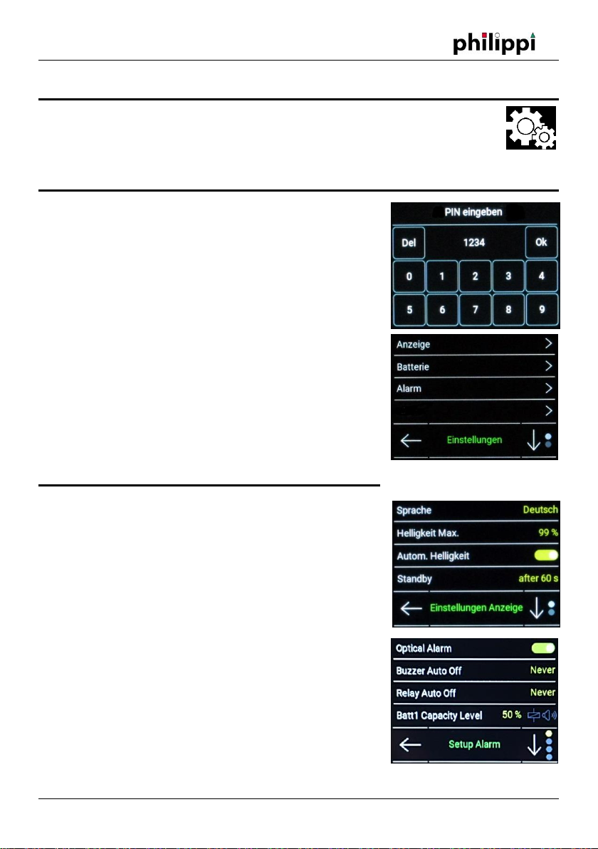
TDN200, UTA). The calibration takes place in the menu TRIM, where the corresponding current
measured values can be entered or determined for the fill levels 0, 25, 50, 75 and 100%.
4.4.3.8 Sensor type DFS ↓
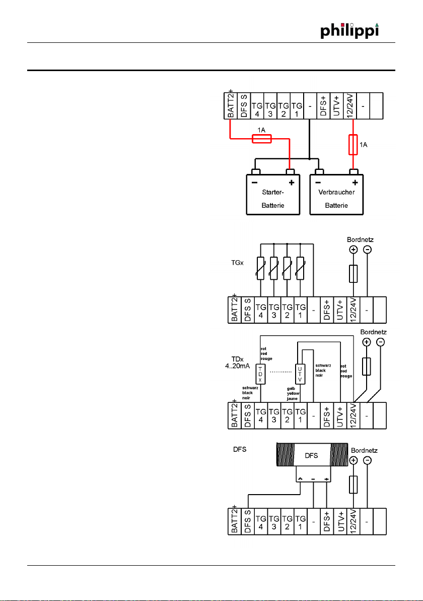
For this setting you need a flow sensor philippi DFS. The connection is only possible on DFS S. The
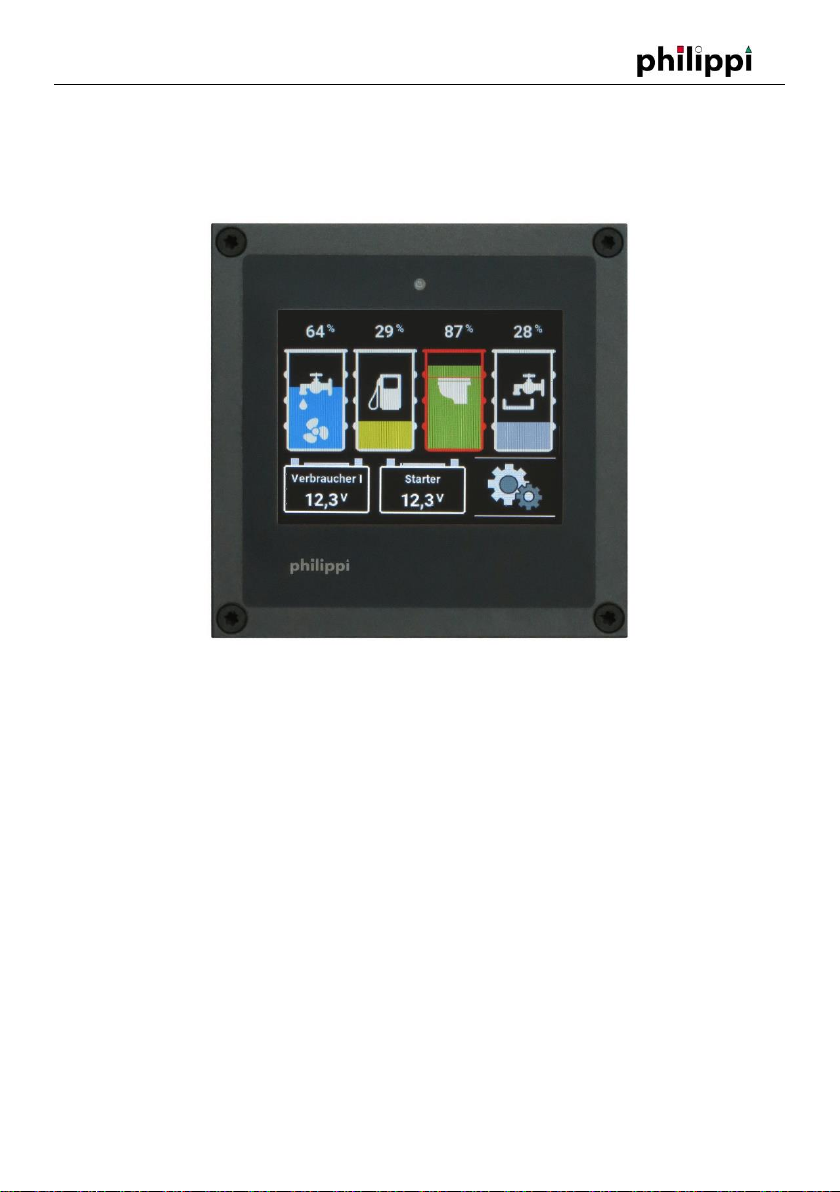
following symbol appears below the respective tank in the main menu:
Since this sensor can not detect whether the tank is being filled, you must enter the fill level
manually. By pressing the assigned key, you can go directly to the tank menu and adjust the level
accordingly. If water flows through the flow sensor DFS, this is indicated by the rotating symbol. The
DFS with arrow down empties the corresponding tank in the display.
4.4.3.9 Sensor type DFS ↑
See 4.6.3.8 - By contrast, the corresponding tank is filled with this setting. This is useful for detecting
the amount of fresh water produced when using a watermaker.
Only one DFS can be connected to the VTM
4.4.3.10 Sensor type TRS/RSW/DSW:
For this setting you need a philippi TRS float switch (mounting on top of the tank) or philippi RSW /
DSW (side mounting). The fuel gauge stays at 0% until the float switch goes through - the display
goes to 100%. There is no series resistor necessary!
4.4.3.11 Sensor type GOBIUS4
The voltage output of the Gobius control unit must be connected to a tank inlet. The level is
displayed in 4 steps. The internal settings of the Gobius system cannot be changed from the VTM.
They have to be adjusted via the Gobius panel.

Tank-Monitor VTM
REV 1A –FEB 2020 - Software Version 1.0 page 11
4.4.4 Trim
To adapt the level indicator to a non-rectangular tank geometry, you have the option of adjusting
the characteristic curve. The respective default settings from the selected encoder type can be
adapted to individual conditions. For the tank types User R, User U, TDS this is absolutely necessary:
Method 1 (Tank is filled step by step):
the probe is in the empty tank. In the setup, you go to the setting
value for 0% and read the measured value at the bottom center
and enter 0% in the Level field. Then fill the tank to 25% and
enter him in the field Level 25%. Analogously, proceed with the
values 50%, 75%, 100%.
This method has the advantage that even if the tank shape is
unusual, the content will be displayed correctly.
Method 2 (installation e.g. TDS200 with full fuel tank):
the probe is outside the tank. In the setup, you go to the setting value for 0% and read the measured
value at the bottom center and enter 0% in the Level field.
Then you install the probe and read off the below measured value and enter it in the field Level
100%. To get the values for 25%, 50% and 75%, you must first divide the difference between the
values 0% and 100% by 4. Add this value to the value at 0% - this gives you the input value for 25%.
By further additions you get the values for 50% and 75%.
These values can be entered in the settings for 25%, 50% and 75%.
Method 3:
You know the values for 0%, 25%, 50%, 75% and 100%? Then enter these values directly in the
corresponding settings.
5. Operation
The tank screen shows the individual tank levels. The measurement takes place automatically after
switching on the monitor and is queried every 5s. The measured values are displayed in the form of
a bar chart. By pressing the tank symbol, it is possible to switch between the display in %, in litres or
without further display. If "----" appears above the associated tank, the measured value of the
associated tank sensor is outside the expected value or no sensor is connected.
The lower button on the right calls up the setup:
SETUP: Here the settings of the battery system can be made. See chapter 4.
In the lower part of the screen up to two battery voltages of the additional batteries are displayed.
The names and corresponding voltage alarm thresholds can be adjusted in the settings.

Tank-Monitor VTM
REV 1A –FEB 2020 - Software Version 1.0 page 12
6. Tips and tricks
If the indication in the display is not correct, always check the tank sensors and their supply lines
first as these are usually the cause of the error.
The Adjustment menu is helpful for this purpose as you can read the current measured value of
the tank sensor there and draw conclusions about the correct function.
7. Software Update
To update the monitors software, a micro SD card is required. After receiving the software, the file
must be copied to the previously empty micro SD card (without folder, top level).
To update, insert the SD card into the SD card slot on the back of the monitor and disconnect the
power supply from the monitor. Then the power is turned on and the screen shows that new
software has been detected and installed automatically. During the update process the progress is
displayed. If the monitor starts normally after inserting the SD card, no SD card has been detected
or the software is up-to-date.
8. Technical data
Supply voltage DC 8-32 V
Current consumption monitor
Without tank sensor connected 83 mA at max. display brightness, 7 mA in sleep mode
Measuring range U1 0-35V, resolution 30mV, accuracy 0.25%
Measuring range U2 0-35V, resolution 30mV, accuracy 0.25%
Dimensions monitor L 105 x W 105 x D 40 mm
9. Declaration of conformity
This device complies with the requirements of the EU directives:
2014/30 / EC "Electromagnetic compatibility"
Immunity EN 61000-6-1
Emitted interference EN 61000-6-3
The conformity of the device is confirmed by the CE mark.
10. Disposal instructions
When disposing of this device, observe the applicable local regulations and use the
collection services / points for waste electrical and electronic equipment.
This manual suits for next models
1
Table of contents
Other philippi Marine Equipment manuals