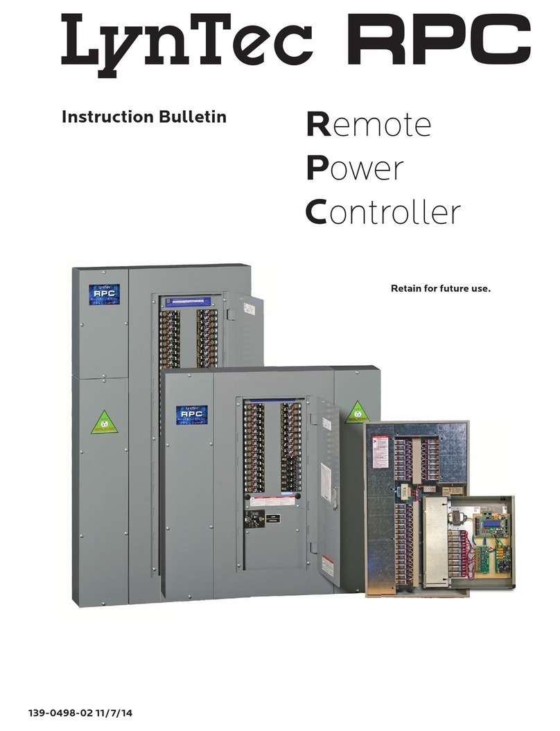
LynTec Xtend Power Controller Training manual

139-0701-01 8/1/19
Xtend
Power
Controller
Instruction Bulletin
Retain for future use.
LynTec XPC

DISCLAIMER LynTec shall under no circumstances be held responsible for any
loss, damage or injury resulting from the use of the XPC in a
manner inconsistent with any of the procedures outlined in this
document.
The user is responsible for determining whether this product is
appropriate for the intended application.
LynTec is not responsible for any indirect, secondary or ancillary
loss or damage, including personal injury, loss of or damage to property
or loss of income resulting from the operation or failure of this unit.

139-0647-01.3 3
XPC Table of Contents
Contents
Disclaimer ................................................................................................................ 2
Chapter 1--Introduction..................................................................................................... 5
OVERVIEW................................................................................................................. 5
CONTENTS ................................................................................................................ 5
Hardware Components ............................................................................................. 5
Software Features .................................................................................................. 6
Front & Back Panel Overview ..................................................................................... 7
Chapter Two--Safety Precautions.......................................................................................... 8
Chapter Three--Quick Start Guide .......................................................................................10
Introduction .............................................................................................................10
Chapter 4--Wiring...........................................................................................................11
Emergency Shutdown Wiring: ....................................................................................11
Switch Wiring Instructions ........................................................................................12
LynTec SS-2 Switch Set ............................................................................................12
SS-2PL and SS-2LRP Locking Switch Sets........................................................................13
Initial Power up procedure............................................................................................14
Chapter 5--Control Setup (Web Page) ...................................................................................15
OVERVIEW................................................................................................................15
Status ....................................................................................................................15
Control ...................................................................................................................15
Setup .....................................................................................................................15
Support...................................................................................................................15
Event Log ................................................................................................................15
Setup..........................................................................................................................16
Setup Home .............................................................................................................16
Network setup...............................................................................................................17
Networking Multiple XRS and XRM Units ............................................................................20
Panel Setup ..................................................................................................................21
Circuit setup ............................................................................................................21
Zone setup...............................................................................................................22
Global Preferences .....................................................................................................26
Setup .....................................................................................................................26
Labeling .............................................................................................................26
Global Control Preferences.......................................................................................26
Selecting Circuits for Emergency Shutdown or Brownout ...................................................27
Voltage Thresholds.................................................................................................27
Schedule Setup .....................................................................................................28
Assigning Schedules to Zones ....................................................................................28
Contact Closure Setup.............................................................................................29
Assigning Contact Closures to Zones ............................................................................29

139-0647-01.4
XPC Table of Contents
Individual Momentary Contact ON and OFF Pushbuttons ....................................................30
Email Alert Setup ..................................................................................................31
Chapter Six: Operating your XPC ........................................................................................32
Using the built-in web page ......................................................................................32
Using a secondary controller .....................................................................................32
Appendix A--Telnet and TCP/IP Protocols ...............................................................................33
Telnet Protocol..........................................................................................................33
Addressing Scheme ................................................................................................33
Circuit Related Commands .......................................................................................33
Zone Related Commands..........................................................................................35
Event Related Commands.........................................................................................36
Checksum ...........................................................................................................38
TCP/IP Protocol.........................................................................................................38
Circuit Control = B .................................................................................................38
Zone Control = Z ...................................................................................................38
Events Control = E .................................................................................................39
Appendix B--Troubleshooting..............................................................................................40
Troubleshooting the XPC ..............................................................................................40

139-0647-01.5 5
Chapter One--Overview
This bulletin explains how to install and operate the
LynTec XPC rack-mount controller. This product is a
controller only and does not contain circuits. Control
signals originate externally from commands received via
the communications network or from dry contact inputs.
Acceptable communications protocols include HTTP,
sACN, DMX-512 and Telnet.
OVERVIEW
Chapter 1--Introduction
CONTENTS
Each XPC comes standard with the following hardware
components installed:
• Ethernet input
• DMX In & Thru inputs
• Emergency override input
• Four contact closure inputs
• Two outbound circuit outputs
• 24V power supply
Introduction
Hardware Components

139-0647-01.66
Chapter One--Overview
Software Features Each XPC comes standard with the following software
features:
• Built-in web server with browser interface for super-easy
set up.
• Circuit level sequencing with selectable individual step-
rates (25ms to 999s)
• Smart phone, tablet or laptop control and monitoring
built in.
• Built in scheduling program with astronomical clock and
84 schedule events.
• Can be interfaced with any control system that
communicates individual circuit addresses in HTTP,
Telnet, DMX, sACN or contact closure.
• Circuit selectable load-shedding feature for emergency
shutoff

139-0647-01.7 7
Chapter One--Overview
Front & Back Panel Overview Figure 1–1 shows the XPC front panel. A brief
description of each part follows in Table 1–1.
Figure 1-1: XPC Front Panel
A
B
C
DE
FG
Table 1-2: Parts of the XPC Front & Back Panel
Component Description
A. LCD Screen Screen shows the IP address
B. Power Input Inputs 24VDC
C. Reset Button Resets the controller.
D. Outbound relays Outbound relays 1 and 2 rated at 1 Amp at 50V
E. Emergency Override &
Contact closure Inputs
One set of contacts for emergency override and four contact closure inputs.
F. DMX Input and Thru Allows the panel to be directed by a secondary DMX controller. When DMX is
enabled, the control page is disabled.
G. Ethernet Port Connects the panel to a computer or network for initial setup or long-term
operation using the built-in web interface. Port also provides sACN connection
Controller Overview
Figure 1-2: XPC Rear Panel Figure 1–2 shows the XPC back panel. A brief
description of each part follows in Table 1–2.
LynTec XPC
Xtend Power Controller
DMX IN & THRU
EO & CONTACT CLOSURES NETWORK
RELAY 1 RELAY 2
RESET
INPUT
24VDC

139-0647-01.8
Chapter Two--Safety Precautions
8
Chapter Two--Safety Precautions
This chapter contains important safety precautions that
must be followed before attempting to install, service, or
maintain electrical equipment. Carefully read and follow
the safety precautions below.
READ AND FOLLOW ALL SAFETY INSTRUCTIONS
IMPORTANT SAFEGUARDS
When using electrical equipment, basic safety precautions
should always be followed including the following:
READ AND FOLLOW ALL SAFETY INSTRUCTIONS.
• There are no user servicable parts inside the XPC. Do not
attempt to service yourself.
• Do not expose the XPC to moisture.
• Do not use outdoors - the enclosure is not rated for outdoor
use
• Do not mount near gas or electric heaters.
• Do not feed after midnight.
• Equipment should be mounted in locations and at heights
where it will not readily be subjected to tampering by
unauthorized personnel.
• The use of accessory equipment not recommended by the
manufacturer may cause an unsafe condition.
• Do not use this equipment for other than intended use.
SAVE THESE INSTRUCTIONS

139-0647-01.9 9
Chapter Two--Safety Precautions
Ce chapitre contient des consignes de sécurité
importantes qui Doit être suivi avant d’essayer d’installer,
de Maintenir l’équipement électrique. Lisez et suivez
attentivement Les précautions de sécurité ci-dessous.
LIRE ET SUIVRE TOUTES LES INSTRUCTIONS DE SÉCURITÉ
GARANTIES IMPORTANTES
Lors de l’utilisation d’équipements électriques, des
précautions de sécurité de base Devrait toujours être suivie, y
compris les suivantes:
LISEZ ET SUIVEZ TOUTES LES INSTRUCTIONS DE SÉCURITÉ.
• Il n’y a pas de pièces utilisables par l’utilisateur à
l’intérieur du XPC. Ne pas Tentez de vous entretenir.
• Ne pas exposer le XPC à l’humidité.
• Ne pas utiliser à l’extérieur - l’enceinte n’est pas évaluée
pour l’extérieur utilisation
• Ne montez pas près de gaz ou de radiateurs électriques.
• Ne pas nourrir après minuit.
• L’équipement doit être monté dans des endroits et à
des hauteurs Où il ne sera pas facilement soumis à une
altération par Personnel non autorisé.
• L’utilisation d’accessoires non recommandés par les Le
fabricant peut causer un état dangereux.
• N’utilisez pas cet équipement pour une utilisation autre que
prévue
CONSERVEZ CES INSTRUCTIONS

139-0647-01.10
Chapter Three--Quick Start Guide
10
Steps Reference
1. Connect power to the 24VDC input Chapter 1--Back Panel Overview
2. Connect the controller to a computer or
network for panel setup.
Chapter 4--Wiring
3. Access the web page by entering the
displayed IP address or NetBIOS name into
web browser on a connected computer.
Chapter 5--Control Setup
4. Complete the setup. Chapter 5--Control Setup
5. Connect the controller to a secondary
controller or add contact closures if
necessary.
Chapter 4--Wiring
Chapter 5--Control Setup
7. If your XPC system does not operate as
expected, verify that everything is installed
and programmed correctly.
Appendix B--Troubleshooting
Chapter Three--Quick Start Guide
INTRODUCTION This chapter is a quick reference listing the steps necessary
to install the XPC system. The steps in this chapter
are provided as an installation checklist. For complete
installation instructions, refer the chapter listed.

139-0647-01.11 11
Chapter Four--Wiring
Emergency Shutdown Wiring: To connect your fire alarm or emergency management
system to the XPC, follow these steps.
1. From the fire alarm unit or latching Emergency Shutoff
switch, wire the contacts to the first pair of inputs on
the rear panel. Default is normally-open, but this can
be changed to normally-closed or monitored-loop in
setup (see Ch. 5)
2. When the contacts change state, all circuits that have
been selected for E. Shutoff will cycle to OFF.
3. When the contacts change state all circuits that were
ON when E. Shutoff was activated will return to the ON
state if “Enable Recovery” is selected (Ch. 5).
See Chapter 5 to configure the software for emergency
shutdown.
Figure 4-1: Emergency shutdown
wiring
Chapter 4--Wiring

139-0647-01.12
Chapter Four--Wiring
12
Switch Wiring Instructions The I/O ports on your XPC controller allow for a variety of
switch options.
LynTec SS-2 Switch Set Using a standard LynTec SS-2 Switch Set with illuminated
ON switch. See Figure 4-2
1. Wire the ON switch to Digital I/O port 2 on the rear
panel as follows:
i. Connect the 24VDC Common to the C pin of the ON
switch. Jumper the C pin of the ON switch to the +
pin.
ii. Connect the Input terminal (arrow pointing towards
header) to the NO pin of the ON switch.
iii. Connect the Output terminal (arrow pointing away
from header) to the – pin of the ON switch.
2. Wire the OFF switch to Digital I/O port 3 on the rear
panel as follows:
i. Connect the 24VDC Common terminal to the C pin
of the OFF switch.
ii. Connect the Input terminal to the NO pin of the
OFF switch
Figure 4-2
Lyntec SS-2 Wiring Diagram
To configure the Digital I/O port and link it to a zone see
Chapter 5.
Repeat on ports 4 &5 for the second zone

139-0647-01.13 13
Chapter Four--Wiring
SS-2PL and SS-2LRP Locking Switch
Sets
Figure 4-3
To configure the Digital I/O port and link it to a zone see
Chapter 5.
Using a standard LynTec SS-2PL or SS-2 LRP Switch Set with
illuminated ON switch. See Figure 4-3
1. Wire the ON switch to Digital I/O port 2 on the lrear
panel as follows:
i. Connect the 24VDC Common to the + pin of the ON
switch.
ii. Connect the + pin on the on switch to the 1 pin on
the lock.
iii. Connect the Input terminal (arrow pointing towards
header) to the NO pin of the ON switch.
iv. Connect the Output terminal (arrow pointing away
from header) to the – pin of the ON switch.
v. Connect the C pin on the ON switch to the 3 pin on
the lock.
2. Wire the OFF switch to Digital I/O port 3 on the rear
panel as follows:
iii. Connect the 3 pin on the lock to the C pin on the
OFF switch.
iv. Connect the Input terminal to the NO pin of the
OFF switch

139-0647-01.14
Chapter Four--Wiring
14
INITIAL POWER UP
PROCEDURE
Connect a computer with an Ethernet port and installed
web browser program to the XPC Network connector using
the provided crossover cable. Then enter the IP address
displayed on the front panel.

139-0647-01.15 15
Chapter Five--Control Setup
Chapter 5--Control Setup (Web Page)
OVERVIEW
STATUS
CONTROL
SETUP
SUPPORT
There are 5 main tabs on your XPC web page. This page
will give you a quick overview of the pages and their
functions.
The status page allows you to view the current status of the
circuits and zones. Zones and individual circuits cannot be
manipulated from this page.
This page allows the user to manipulate individual
circuits as well as circuit zones. “All ON/OFF” and
“Hurry-Off” commands can also be triggered from this
page.
The setup section allows you to setup and use the
XPC controller. From this section you can manipulate
the network settings, assign circuits to zones, create
sequences, activate emergency management features,
create schedules and assign contact closures.
This page provides contact information for LynTec.
EVENT LOG This page provides a log of events.

139-0647-01.16
Chapter Five--Control Setup
16
Setup
SETUP HOME Figure 5-1--Setup Home
This section will guide you through the process of setting
up yur XPC Controller. First enter the IP address or NetBios
name into your web browser. When the XPC screen pulls
up. Select “Setup” and “SetupHome” Tabs.
To set the username and password for your panel, click
the Setup tab. The Setup Home tab should be displayed.
The default username displayed is “admin” and the
password fields is “pw”. Enter the desired username in
the first field, password (without spaces or symbols) in
the second and then retype the password again in the
third field. When ready, click the Update Login Info button
to save the changes to the controller’s memory. Note:
Password can be any 2-8 character string.
Contact information for service can also be entered
on this page. Under the Serial Number field, enter the
name and phone number of the installing contractor
(Electrician) and the system integrator (A/V Technician)
for future reference. Save this information by clicking the
Update Information button below the Clock Set portion of
the window.

139-0647-01.17 17
Chapter Five--Control Setup
Network setup
Figure 5-2--Network Configuration Figure 5-2 shows the network configuration portion of the
Network setup.
Basic date and time information will be displayed in the
Clock Set fields. Verify that the year, month and day are
correct. Set the hour to the appropriate time for your time
zone and verify that the minute displayed is correct. Save
this information by clicking the Update Information button
below the Clock Set portion of the window.
Click the radio buttons for any pages to be printed out
under the Printable Pages header. To print the Network
Setup, Panel Setup or Panel Schedules pages at any time,
ensure the desired buttons have been selected and then
click the Print Pages button to the right. Please print a
copy for your records after setup is complete.
This screen shows the current network values. If DHCP
is enabled then the fields will be greyed out. It is
recommended that the user consult with the network
administrator before changing these values.
The IP, Subnet and Gateway addresses are only used in the
following situations:
• When DHCP is disabled
• When DHCP is enabled, but there is no DHCP server
available on the network
• When the XPC provides DHCP addresses
If DHCP is enabled and available on the network, all these
values will be obtained from the DHCP server.
If DHCP is disabled and a static address is used, save
changes and then press “Reset RPC” or the reset button on
the controller to apply changes.

139-0647-01.18
Chapter Five--Control Setup
18
Figure 5-3: Interface options
Port Type The port type section is used to select the preferred
communication protocol. The controller defaults to
Ethernet (TCP/IP) for setup but can be controlled in
conjunction with sACN or DMX-512 protocols.

139-0647-01.19 19
Chapter Five--Control Setup
DMX For DMX operation use the following steps:
The XPC allows up to four different sets of DMX starting
addresses within a single universe.
In the first set, enter the first circuit address. All
circuits need to be assigned addresses manually. Do
this by clicking on each circuit in the order you would
like them to be addressed. If you need to skip an
address or group of addresses, simply create a new
zone and enter the desired starting address. If you
would like the XPC to automatically assign circuits to
consecutive addresses. you may change that in the
Please note that selecting sACN/DMX control for a
circuit or zone, will disable web browser or contact
closure control for that circuit/zone. Although,
circuit/zone status may still be monitored by web
browser or smartphone.
DMX and sACN are exclusive and cannot be used on
the same controller at the same time. Either can be
used to control circuits in zones while other zones are
controlled by IP commands or contact closures.
Streaming ACN E1.31 For sACN operation use the following steps:
The XPC allows up to four different universes with
sACN operation.
First, assign a number to the universe.
In the first set, enter the first individual circuit address.
All circuits need to be assigned addresses manually.
Do this by clicking on each circuit in the order you
would like them to be addressed. If you need to skip
an address or group of addresses, simply create a new
zone and enter the desired starting address. If you
would like the XPC to automatically assign circuits to
consecutive addresses. you may change that in the
“Panels” tab.

139-0647-01.20
Chapter Five--Control Setup
20
NETWORKING MULTIPLE
XRS AND XRM UNITS
Up to 9 XRS and XRM units may be networked together
to allow for zoning and sequencing across all units. To
connect XPCs together use the following steps:
1. Connect all Xtend units to the network on the same
subnet.
2. The XPC will be the “master” unit.
3. In the web interface click the “Setup” tab and then
the “Network” tab.
4. Under “Master/Remotes IP Configuration” enter the
IP address for each remote unit.
Figure 5-3.1: Master/Remotes IP Configuration
Table of contents
Other LynTec Controllers manuals