NL88
MOTION SENSOR
BULKHEAD LIGHT
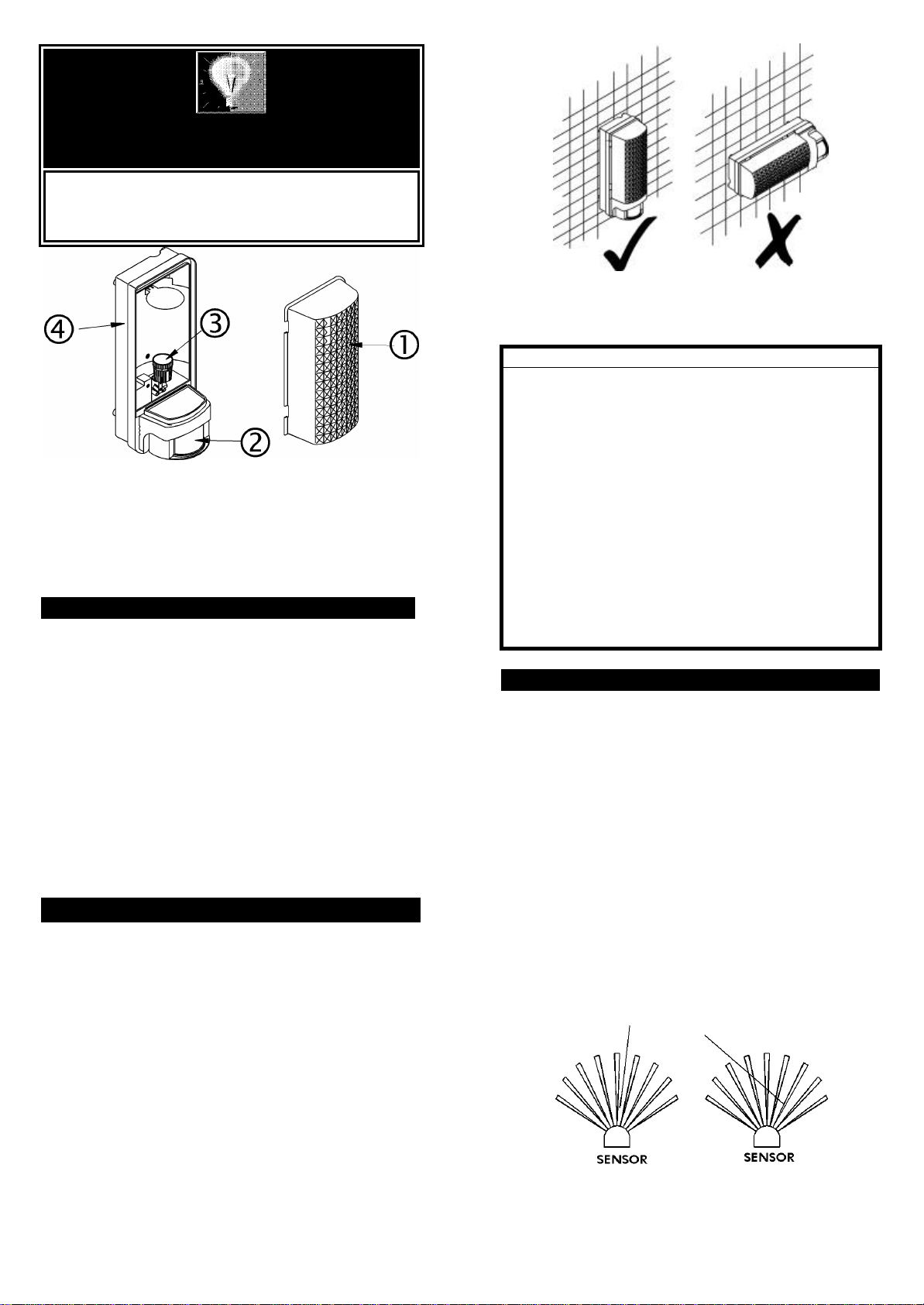
•Lamp Shade
‚PIR Motion Sensor
ƒBulb Holder
„Bottom Housing
INTRODUCTION
Your EVERSPRING MOTION SENSOR BULKHEAD
LIGHT is a unique lighting system for your home or
business. At night, the built-in passive infrared (PIR)
motion sensor turns on the floodlight when it detects
motion in its coverage area. During the day, the built-in
photocell sensor saves electricity by deactivating the
floodlight. Time and Lite adjustment functions let you
select how long and when the light will stay on after
activation. Two operation options let you choose:
Automatic Operation or Manual Override.
Note: Read this entire manual before you start to
install the system.
SAFETY PRECAUTIONS
lDo not install when it is raining.
lBe sure to switch off power source before installing.
lMake sure that the power wiring comes from circuit
with an external 16A miniature circuit breaker for the
short circuit protection or a suitable fuse.
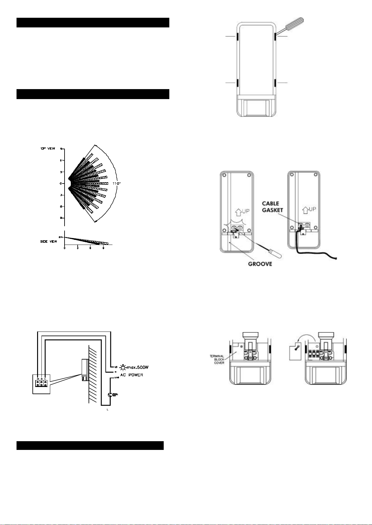
lKeep minimum 0.8m away from the lighted objects.
lThe unit can be installed only vertically (FIGURE 1a),
not horizontally (FIGURE 1b).
VERTICAL HORIZONTAL
FIGURE 1a & 1b
IMPORTANT
Some local building codes may require installation of
this product by a qualified electrician.
Check your local codes as they apply to your situation.
If the house wiring is of aluminum, consult with an
electrician about proper wiring methods.
Maintenance or repairing work such as replacing
current fuse shall be done by a qualified electrician or
technician.
Before proceeding with the installation, TURN OFF THE
POWER TO THE LIGHTING CIRCUIT AT THE CIRCUIT
BREAKER OR FUSE BOX TO AVOID ELECTRICAL
SHOCK.
CHOOSING A MOUNTING LOCATION
lFor the best results, fix your motion sensor light on
a solid surface, 1.8~2.5m above the ground.
lFor outdoor installation, a location under eaves is
preferable.
lAvoid aiming the motion sensor at pools, heating
vents, air conditioners or objects that may change
temperature rapidly.
lDo not allow sunlight to fall directly on the front of
unit.
lTry to avoid pointing the unit at trees or shrubs or
where the motion of pets may be detected.
lPrior to mounting, keep in mind that the motion
sensor is more sensitive to the motion, which is
across the detection field and less sensitive to the
motion, which moves directly towards the detector
(FIGURE 2).
LESS SENSITIVE MORE SENSITIVE
SENSITIVITY TO MOTION
FIGURE 2
1