Lynx S-60 User manual
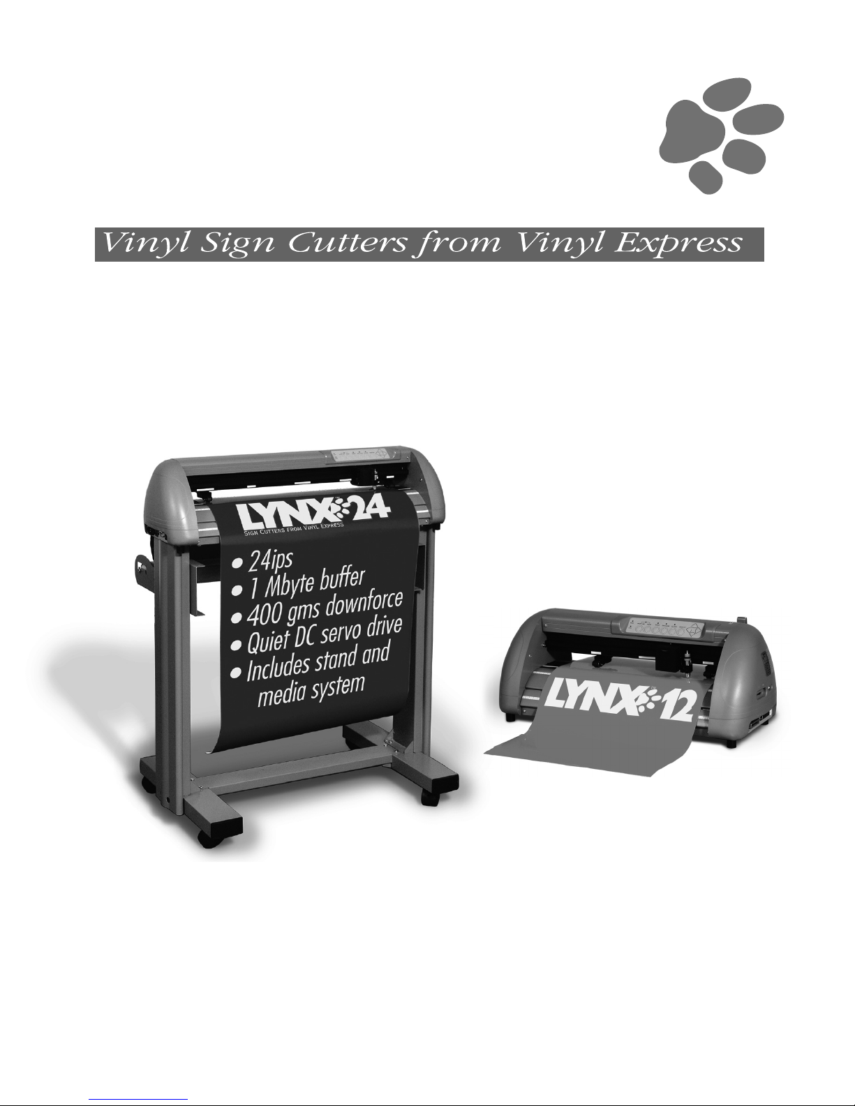
L
YNX ™
SIGNWarehousecom
lynx_man_rev1_0504
User's Guide
®

1. – Learning
1.1 Initial Inspection 1-1
1.2 Front View of Lynx 1-2
1.3 Back View of Lynx 1-2
1.4 Side View of Lynx 1-4
2. – Installation
2.1 Installation 2-1
2.2 Stand and Media Handling System Installation 2-2
2.3 Blade Installation 2-6
3. – Connecting the Cutter
3.1 Parallel Transmission 3-1
3.2 Serial Transmission 3-1
3.3 Transmitting the data to the plotter 3-2
3.4 Interface for Macintosh Plus/SE/II 3-2
3.5 USB Port 3-3
4. – Basic Operation
4.1 Loading the sheet media 4-1
4.2 Loading the roll media 4-3
4.3 Control Panel 4-6
4.4 Power On 4-7
4.5 ON/OFF Line Key 4-8
4.6 Pause Key 4-8
4.7 Repeat Key 4-9
4.8 Data Clear Key 4-9
4.9 Origin Setting 4-9
4.10 Dip Switch Setting 4-10
4.11 Adjusting the Offset Value 4-10
4.12 Tracking Performance 4-12
4.13 Cutting Test 4-13
4.14 Adjusting the Tool Force 4-14
4.15 When Completing the Cutting Job 4-14
5. – Care & Basic Maintenance
5.1 Cleaning the Cutter 5-1
5.2 Cleaning the Grid Drum 5-2
5.3 Cleaning the Pinch Rollers 5-2
6. – Troubleshooting
6.1 If the Cutter is not Operating 6-1
6.2 Light Indicators 6-2
6.3 Warning Indicators 6-2
6.4 Error Indicators 6-4
6.5 Cutting Quality Problem 6-5
Appendix I – Specifications
Quick Menu I
Important Information II
About The Tool III
Optional Accessories IV
Equipment Specification V
Table of Contents

1.1 Initial Inspection
Before setting up your cutter/ plotter, please carefully unpack and inspect what you have received from
the shipped carton by comparing them with the following listed items. If you discover any item missing
in the process of delivery, please call Customer Service.
Item Quantity
Cutting Plotter Body
Accessory Bag
Roll Base
Serial Cable (RS-232C)
Cutter Tool
Cutting Pad
Tweezers
User’s Guide
AC Power Cord
Blade Holder
Blade (PLTB-ROLAND-45)
Water-Based Fiber-Tip Pen: 0.3 mm tip width
Parallel Cable
1
1
1
1
1
1
1
1
1
1
1
1
1. Learning About Your Cutter 1-1
24” Lynx Optional Item Quantity
Stand & Flexible Media Support System includes:
(Please see 2-1 for Installation)
• Stand set and accessory box
• Roll Media Flange
• Roll Holder
• Roll Holder Guide bushes
• Roll Holder Support
1
2
2
4
2
1. Learning About Your Cutter
1. Learning About Your Cutter 1-2
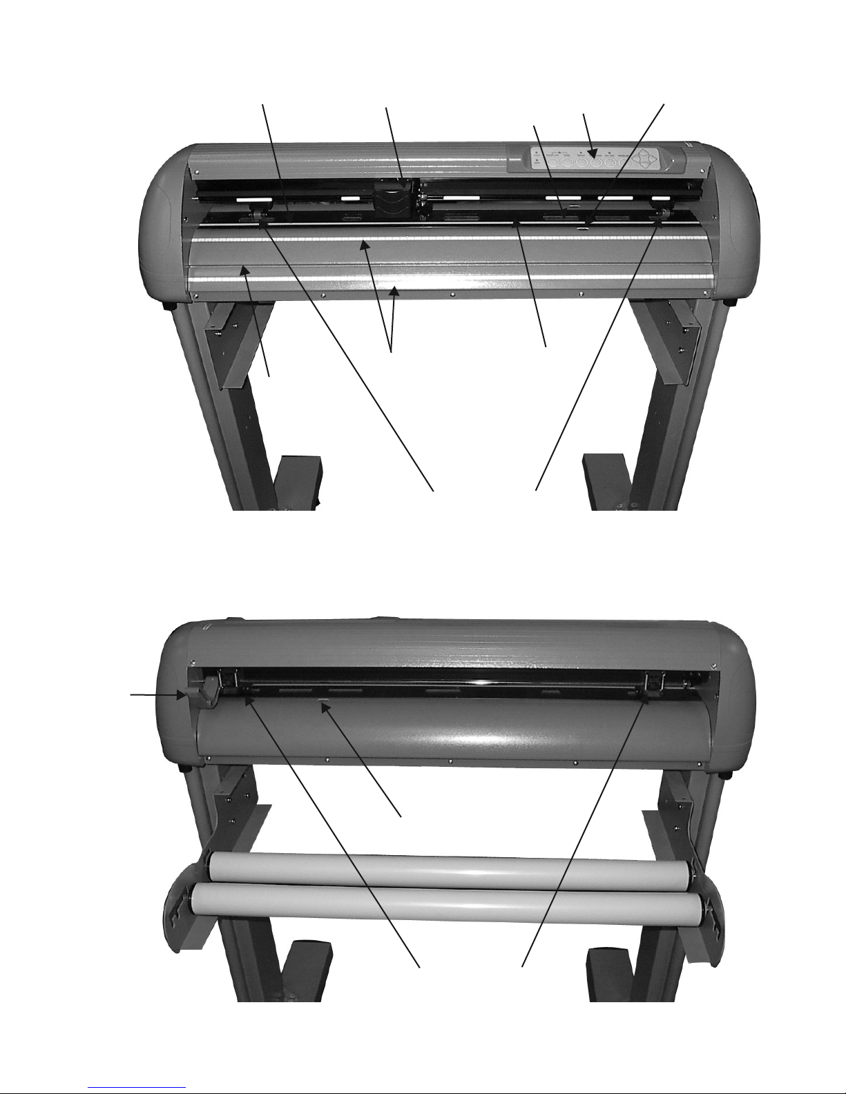
1.2 Front View of Lynx ( see Figure 1-1)
Platen
Knife Guide
Cutting Pad
Grid Drum
Control Panel
Tool Carriage
Alignment Rulers
Pinch Rollers
Figure 1-1
Paper Sensor
1.3 Back View of Lynx ( see Figure 1-2)
Lever
Figure 1-2
Paper Sensor
Pinch Rollers

1. Platen - Provides the surface for holding and supporting media during cutting.
2. Cutting Pad - Provides protection for the blade while the blade is cutting.
3. Alignment Ruler – Media can be aligned with the clear guide line marks.
4. Tool Carriage – This unit performs the cutting with the installed blade and pen
5. Grid Drum - Moves the media back and forth during operation.
6. Control Panel - Consists of 10 control keys and 6 LEDs.
7. Pinch Roller – Presses the media against grid drum during cutting.
8. Knife Guide – Easily cuts off extra media with this groove.
9. Lever - Raises or lowers the pinch rollers.
Optional Items (see Figure 1-3)
1. Roll Holder – Consist of two rollers to hold and feed the roll media for cutting.
2. Roll Holder Guide Bushings - Serves to keep the roll media in place when media is pulled from the roll.
3. Media Roll Flanges - Secures media roll flanges in place.
4. Roll Holder Support - Supports roll holders.
5. Stand - Supports the cutting plotter body.
1. Learning About Your Cutter 1-3
Figure 1-3
Media Roll Flanges
Roll Holder
Roll Holder Support
Stand

Left Hand Side (Figure 1-4)
1. AC Power Connector – Used to insert the AC power cord.
2. Fuse – Up to 3 Amps.
3. Voltage Switch – The presetting is 230 voltage. Please adjust to comply with your local standard.
4. Power Switch – On when switches to [I]; Off when switches to [O]
Right Hand Side (Figure 1-5)
5. Dip Switch label – Indicates the functions of the dip switches.
6. Dip Switch - Used for various parameter settings.
7. Pen Force Control Slider – Set the blade force here.
8. Universal Serial Bus Connector- Used in conjunction with Windows Printer Drivers to connect
the cutting plotter to a computer through a Universal Serial Bus Cable.
9. Serial Interface Connector (RS-232C) – Used to connect the cutting plotter to a computer
through a serial interface cable.
10. Parallel Interface Connector (Centronics) –Used to connect the cutting plotter to a computer
through a parallel interface cable.
This is a vinyl cutter. It is not intended to be used with windows drivers or as a printer.
Signwarehouse.com does not recommend that you use these drivers.
1. Learning About Your Cutter 1-4
Figure 1-4 Figure 1-5
1.4 Side View of Lynx
1 2 3 4
7
5
6
8 9 10

2. Installation
2.1 Installation
Caution 1
• Make sure the power switch is off before installing the cutting plotter.
• Carefully handle the cutter to prevent any injuries.
Caution 2 Choosing a proper place before setting up the cutting plotter
Before installing your cutting plotter, select a suitable location, which meets the following conditions.
• The machine can be approached easily from any direction.
• Keep enough space for the machine, accessories and supplies.
• Keep the working area stable, avoiding severe vibration.
• Keep the temperature between 41o-104oFin the workshop. (High temperature may damage vinyl).
• Keep the relative humidity between 30% and 70% in the workshop.
• Protects the machine from dust and strong air current.
• Do not place machine in direct sunlight.
Caution 3 Connecting the Power Supply
Check the plug of the power cord to see if it mates with the wall outlet. If not, please contact your dealer.
• Insert the plug (male) into a grounded power outlet.
• Insert the other end (female) of power cord into the AC connector of the cutting plotter.
2. Installation 2-1
2.2 Stand & Flexible Media Handling System Installation
(The Stand and Flexible Media Support System for Lynx S-60 is optional)
Step 1
Examine supplied items in the accessory box of stand carton:
• 20 pieces of M6 (Alan head) screws
• 20 pieces of spring washers
• 20 pieces of washers
• 4 pieces black wheels (casters)
• 1 piece of M6 L- shape hexagon screw driver
• 1 piece of M6 wrench
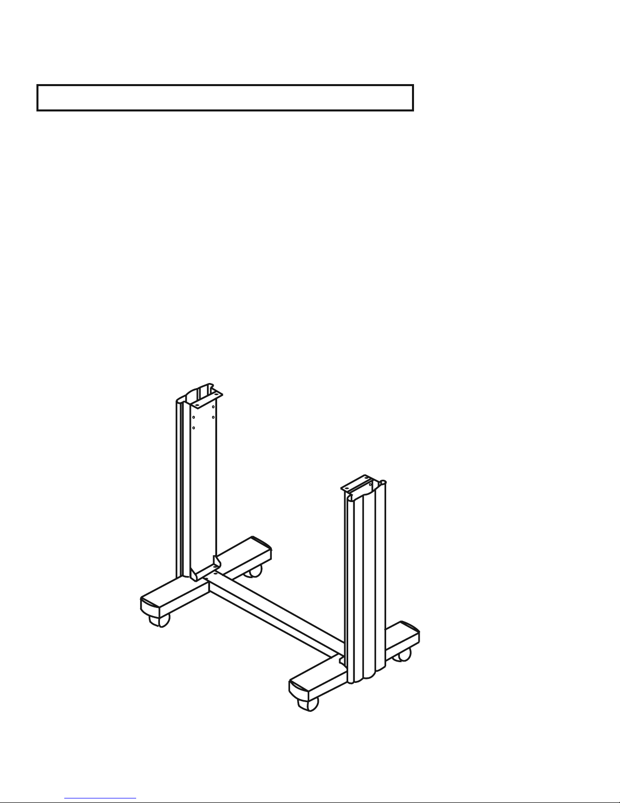
Step 2
• The stand includes five parts as Figure 2-1, follow the figure number to assemble.
Figure 2-1
2. Installation 2-2

Step 3
• Use M6 screws, washers and spring washers to assemble part 1and 2, then use the screwdriver to
tighten them; this creates an H-shaped base. Figure 2-2 and 2-3 (reverse of the H-stand) will show you the
position to insert screws.
Step 4
• Insert the black wheels with washers into the holes on the bottom of H-shape stand as shown in Figure
2-4. Use the wrench to fasten them.
Figure 2-2 Figure 2-3
Figure 2-4
2. Installation 2-3
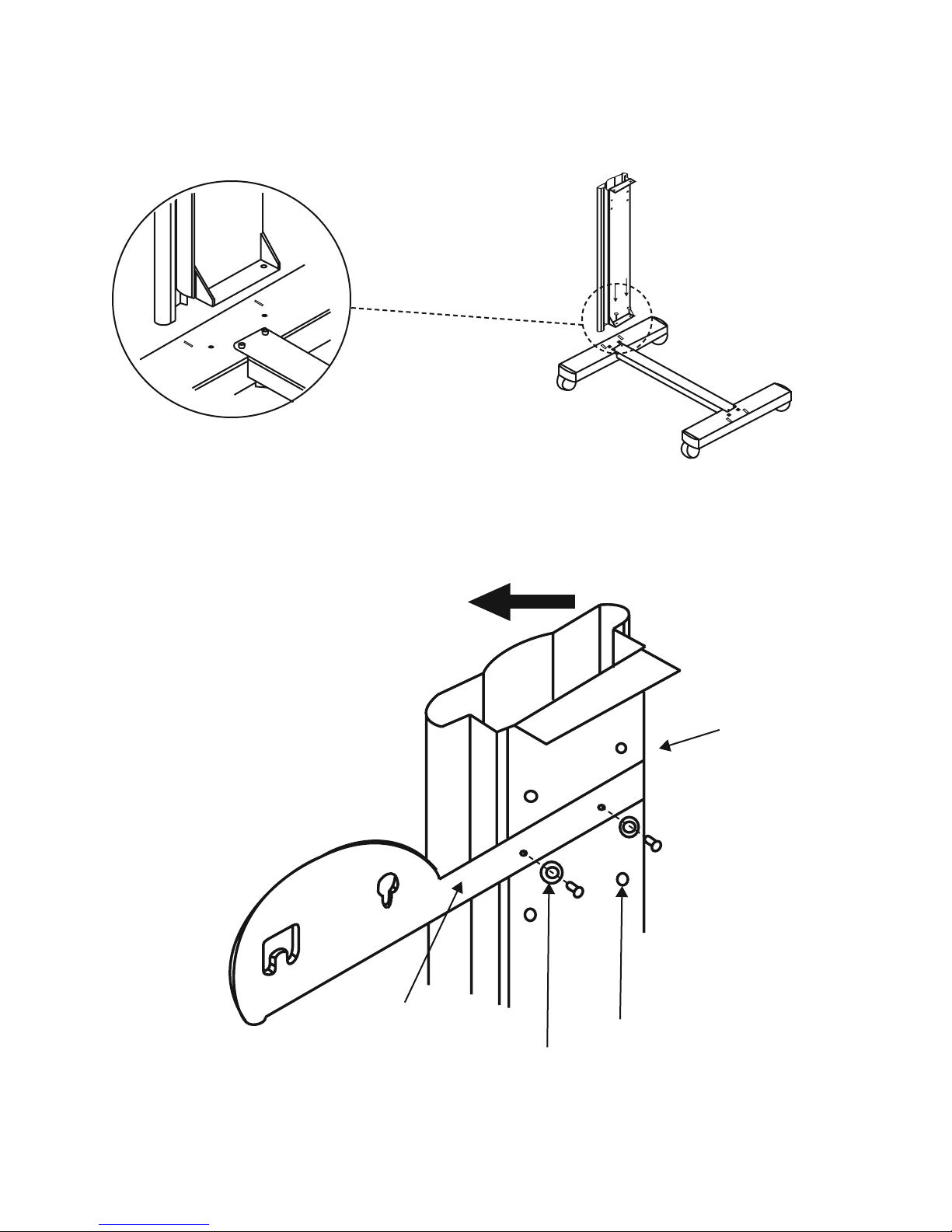
Step 5
• Then connect part 3and H-shape stand. First, position the extension of part 3into the squares holes on
H-stand. Second, insert the screws and washers into the holes besides the squares then tighten them (Figure 2-5).
Step 6
• Remove the cutting plotter from the carton. Position your stand under the plotter, then insert the screws
into the holes on plotter’s bottom. In order to make the task easier, you may need someone to help you.
Figure 2-5
Figure 2-6
Extension
Square holes
Screws holes
3
2. Installation 2-4
This manual suits for next models
1
Table of contents
Popular Cutter manuals by other brands

Milwaukee
Milwaukee HEAVY DUTY M12 FCOT Original instructions

SignWarehouse.com
SignWarehouse.com Bobcat BA-60 user manual

Makita
Makita 4112HS instruction manual

GEISMAR STUMEC
GEISMAR STUMEC MTZ 350S manual

Hitachi
Hitachi CM 4SB2 Safety instructions and instruction manual

Dexter Laundry
Dexter Laundry 800ETC1-20030.1 instruction manual


