3
IMPORTANT PLEASE READ AND FOLLOW!
5. Place cabinet(s) in approximate nal position.
Level cabinets using leveling legs. If installing two
or more cabinets, use 1/2”SMS screws provided
to screw them together. (See illustration #3).
6. On cabinets with interchangeable left or right hand swing, determine appropriate hinge side for cabinets. Remove handle and
outside door panel. Remove hinges and hole plate covers. Install hinges on opposite side by placing hinge bracket in hole in
door and fasten in place with hardware provided. Screw hole plate covers in appropriate pre-drilled holes in cabinet side. Fasten
hole covers with hardware provided. (See Illustration #4).
7. Cabinet doors must be adjusted when cabinets are level in
nal position. There are two adjustment screws on the hinge
receiver. (See Illustration #5)
•The front screw is used to center the door in the
opening. Turning the front screws in or out will center
the door over the cabinet opening.
•The back screw is used to align the front of the door
with the cabinet frame and secure the door to the
cabinet. Slightly loosen the screw and slide door in or
out. Retighten the screw to secure the door.
Illustration #5
Hinges:
Remove both hinges. Use #8-32 x 3/8”(.95 cm)
Phillips head, M.S. and locknuts to replace hinge
brackets to the inside door panel.
With inner door panel removed:
Hole Covers:
For models with interchangeable swing, remove
both hole covers:
Use #8-32 x 3/8”(.95 cm) Phillips head, M.S. and
locknuts to fasten hole covers to opposite side of
inside door panel.
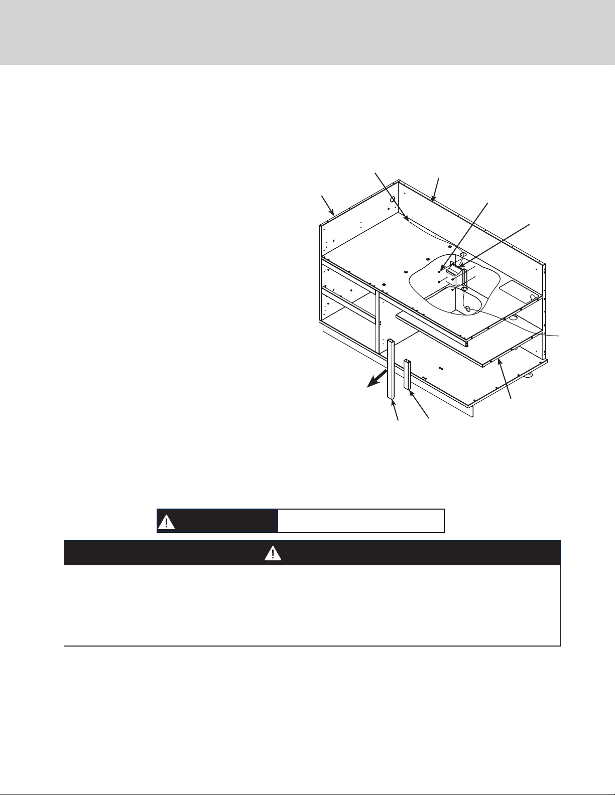
Illustration #3
Install (4) Tinnerman clips (provided)
before fastening cabinets together.
Mount cabinets with
#10 x 1/2”(1.3 cm)
screws provided.
Back
Screw
Front
Screw
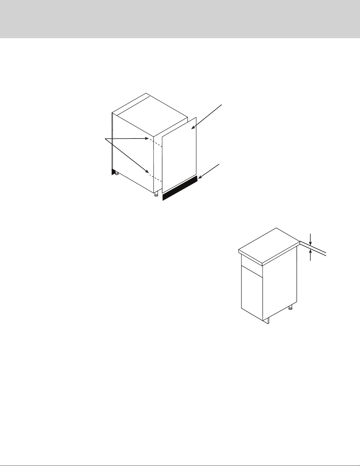
Remove / Replace door panel
Remove / Install Hole Covers and Hinges
Illustration #4
Remove screws holding the handle
brackets from the inside door panel.
Remove and save screws located at
bottom of outside panel. Note: Number
of screws may vary by model.
Lift the inner door panel away to remove
from outer door panel.
Remove the screws and handle brackets
from the handle on the outer door panel.
Reverse steps for door panel
replacement.