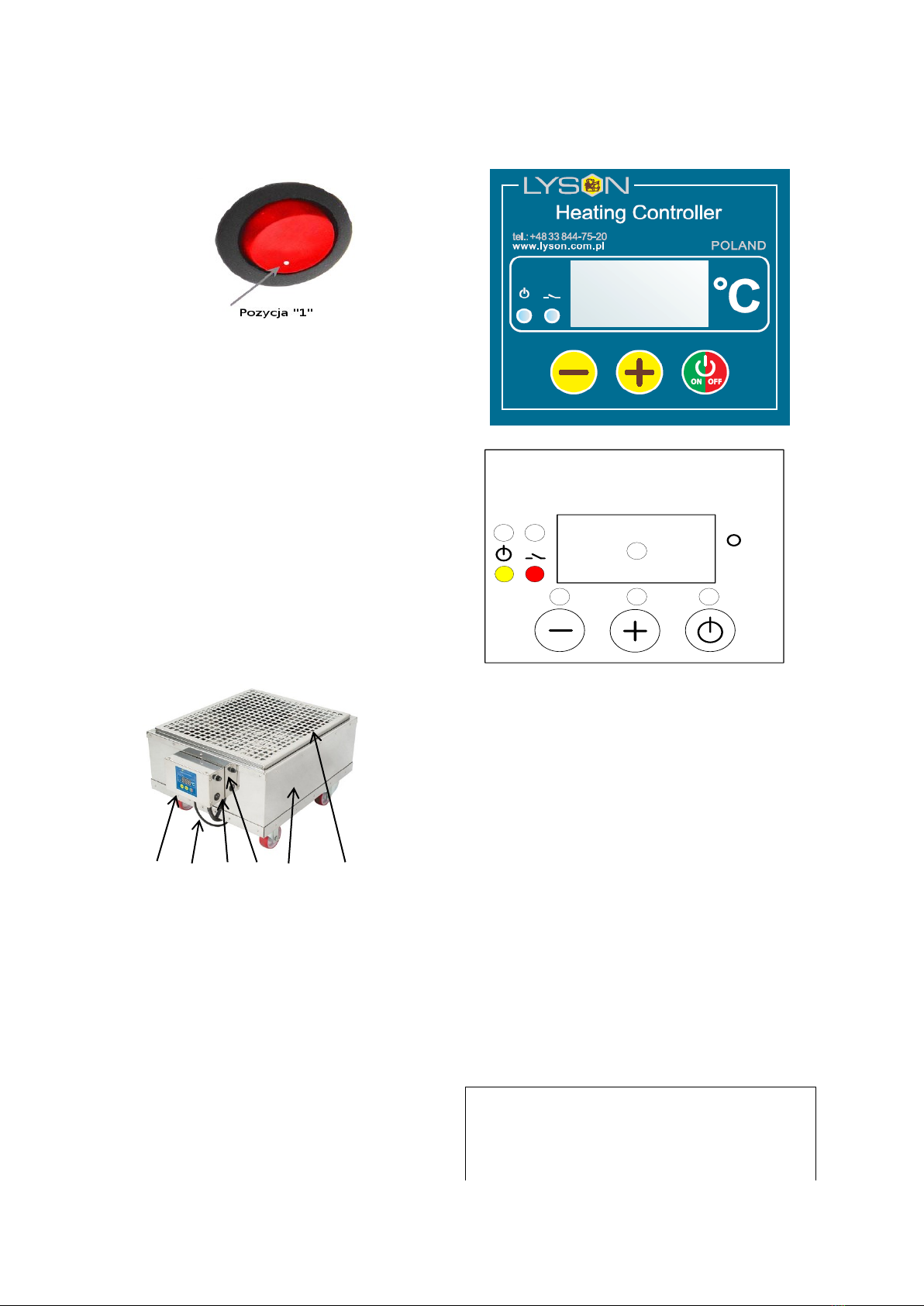
LYSON W3012 User manual

1
The following manual encompasses
the device bearing the following
code:
W3012
Manual
1. General safety operational
principles for the device
1.1. Operational principles
1.2. Electrical safety
1.3. Operational safety
2. Manual
2.1. Operational principles
3. Device characteristics
3.1. Device description
3.2. Controller description
3.2.1. Controller set-ups
3.2.2. Starting work with
controller
3.2.3. Error report for controller
3.2.4. Controller technical
parameters
3.2.5.Technical data
4. Device storage
5. Maintenance and cleaning
6. Recycling
7. Guarantee
1. GENERAL SAFETY

2
OPERATIONAL PRINCIPLES
FOR THE DEVICE
Prior to device usage initiation, refer to the
following manual and act according the
guidelines contained therein. The manufacturer
shall not be held accountable for any damages
caused by improper usage of the device or its
improper handling
.
1.1. Operating principles
1. The heater is intended to heat up the bodies
with the frames before spinning and uncapping
2. Prior to starting work, the temperature regulator
should be set for required temperature value and
time.
1.2. ELECTRICAL SAFETY
1. Power supply electric installation must be
equipped with RCD with nominal tripping current
In below 30 mA. Functioning of overcurrent circuit
breaker must be checked periodically.
2. Do not operate the pre-heater when the power
supply cable is damaged!
3. Prior to connecting the device to the mains,
make sure that controller is off. A switch on the
controlling panel should be in “0” position
4. While connecting to the mains, be careful.
Hands must be dry! The floor on which the device
is placed must be dry too!
5. Do not displace the pre-heater containing
honey while in operation
6. Protect the controller against humidity (also
during the storage).
7. It is forbidden to pull the power supply cable.
The power supply cable must be kept away from
any heat sources, sharp edges and its proper
state must be secured.
.
1.3. OPERATIONAL SAFETY
The following equipment is not intended to be
used by persons with limited physical,
sensory or mental capabilities (including
children) or persons inexperienced or
unfamiliar with that type of equipment unless
the usage occurs under supervision or in line
with the equipment operating manual
provided by safety supervising persons.
Make sure that children do not play with the
device.
2. The floor on which the device has been
positioned must be levelled off, solid and dry!
3. Prior to starting work with the device, the
bodies must be covered (e.g. by means of a
roof).
4. Do not displace the heater while in
operation .
5. It is forbidden to perform any maintenance
works when the device is in operation .
6. In case of any danger, the device must be
switched off immediately.
7. The device may be reactivated once the
danger has been eliminated.
8. Do not use the device in the vicinity of any
flammable materials.
9. Do not switch on the heater without the
bodies with frames or without jars for de-
cristalization.
10. The device must not be switched on and
stored with the ambient temperature below
0º C. Prior to the device activation, when it
has been brought from a room with lower
temperature to a room with higher
temperature, wait until the device has
reached the ambient temperature.
11. The device may be activated indoors only.
The device is not suitable to be operated
outdoors.
.
2.MANUAL
2.1. Operating principles
1. The heater is intended for heating up the
bodies with the frames or de-crystalization.
2. Prior to start-up, one must:

3
Plug the device into a socket, switch on the
controller’s box must be moved from „0” position
to „1” position
3. DEVICE CHARACTERISTICS
3.1. Device description
The heater is made of stainless steel and is
intended to heat up the bodies in non-heated
workshops. The heater is adjusted to the bodies
made by: Dadant, Langstroth, WL 12-frame ones.
When the adapting inlet is used, the bodies type
Ostrowska or Wielkopolska can be used. The
bodies requiring heating up before uncapping or
spinning shall be placed on the heater for several
hours. Warm air goes through forced air flow and
flows between the frames heating them up, which
ameliorates spinning and uncapping
1 2 3 4 5 6
Device components :
1) Temperature regulator HC-01
2) Power supply cable 230V
3) Main switch 0-1
4) 5A fuse holder
5) Stainless steel body
6) Stainless steel shelf, perforated , for de-
crystalization of jars with honey
3.2. Controller description
HC-01 temperature regulator has been mounted
in the device.
Heating Controller
c
4 5 6
3
1 2
3.2.1. Controller’s set-up
1. Prior to plugging in the device to the mains,
one must make sure that the controller is switched
off.
Switch (0/1) on the control panel shall be in
“0” position
Once plugged in to the mains, Switch (0/1)
shall be moved from “0” position to “1”
position
Controller should be programmed in line with
individual needs
In order to enter the programming mode
(Prog), buttons “+” and “-“ must be pressed at
the same time during controller start-up
3.2.2. Starting work with the
controller
1 –signalling the work state
Indicator lights up –temperature regulator
switched on, indicator dimmed –temperature
regulator switched off (controller operates as an
ordinary thermometer), indicator flashes –

4
temperature regulator switched on and initial
heating in progress
2 –signalling the activation of heating
transmitter
Indicator lights up –transmitter contacts closed
(heating on), indicator dimmed –contacts opened
(heating off)
3 –display
Working mode –default mode, selected after
controller power supply switched on. The display
shows the measured temperature, readings
specified in oC.
Setting mode –selected when button “+” or “-
“ has been pressed. The display shows the preset
temperature. Readings specified in oC. Reading
flashes and returns to measured temperature
after a while.
Working time setting mode (Pro.) –activated
when “ON/OFF” button is pressed and held. The
display shows working time, counting it from
activation, after which the thermostat gets
switched off. Readings specified in hours.
Display brightness setting mode (d.br.) –
activated when “ON/OFF” button is pressed and
held for a longer time. The display shows the
currently set brightness on all its segments .
When the setting limit values are reached, the
segments start to flash.
The modes specified below are accessible
once the relevant code have been entered.
Calibration mode (CAL.) code L-1 –activated
when the “ON/OFF’ button has been pressed and
held for a longer time. The display shows the
measured temperature including the calibration.
Readings specified in oC.
Preliminary heating time setting mode (P.tI.)
code L-2 –activated when “ON/OFF” button is
pressed and held for a longer time. The display
shows the working time, counting it from the
activation, for which the controller performs
preliminary heating maintaining the preliminary
heating temperature programmed by the
manufacturer. Reading “OFF” means deactivation
of the preliminary heating function. Readings
specified in minutes. When preliminary heating
activated, the controller displays marking “HC2”
during start-up.
Preliminary heating temperature setting mode
(P.tE.) code L-3 –activated when the “ON/OFF”
button is pressed and held for a longer time. The
display shows the value of preset temperature for
preliminary heating. Readings P … specified in
oC.
Preset temperature limit setting mode (L.t.h.)
code L-4 –activated when “ON/OFF” button is
pressed and held for a loner time. The display
shows maximum value of preset temperature that
can be set . Readings L … are specified in oC.
4 –button „-„ value decreasing
Working mode –pressing the button will
decrease the preset temperature value. During
preliminary heating, the option to change the
setting for preset temperature is blocked.
Working time setting mode –pressing the
button will decrease the time after which the
thermostat will get switched off.
Display brightness setting mode –pressing the
button will decrease the brightness of the display.
Calibration mode –pressing the button will
decrease the value of the temperature to be
transferred, calibrating the measurement duct in
this way.
Preliminary heating time setting mode –
pressing the button will decrease the time after
which the thermostat will switch from preliminary
heating phase to proper heating phase.
Preliminary heating temperature setting mode
–pressing the button will decrease the value of
preset temperature that will be maintained during
preliminary heating.
Preset temperature limit setting mode –
pressing the button will decrease the value of
maximum preset temperature that will be to set.
5 –button „+” value increasing
Working mode –pressing the button will
increase the value of preset temperature. During
preliminary heating, the preset temperature
setting changes is blocked.
Working time setting mode –pressing the
button will increase the time after which the
thermostat gets switched off.
Display brightness setting mode –pressing the
button will increase the brightness of the display
Calibration mode –pressing the button will
increase the value of the transferred temperature,
calibrating the measuring duct in this way.
Preliminary heating time setting mode –
pressing the button will increase the time after
which thermostat switches from preliminary
heating phase to proper heating phase.
Preliminary heating temperature setting mode
pressing the button will increase the value of
preset temperature which will be maintained
during preliminary heating.
Preset temperature limit setting mode –
pressing the button will increase the value of
maximum preset temperature that can be set
6 –„ON/OFF” button
Short-time pressing of the button will activate
(ON) and deactivate (OFF) the regulator
interchangeably. At deactivated state (OFF) the
regulator act as a thermometer. At activated state
(ON) , the regulator shall activate and deactivate
the outlet to control the heater in order to maintain
the temperature set by the user.
Longer pressing and holding of the button and
subsequent button releasing will activate the

5
working time setting mode, signalled with (Pro.)
notice. In this mode, by means of “+” and “-
“ buttons , the user has a possibility to define the
time after which the controller gets deactivated,
i.e. switches to the OFF state. Exit from the mode
and setting approval occurs once the “ON/OFF”
button is shortly pressed.
Longer pressing and holding of the button and its
subsequent releasing will activate the display
brightness setting mode –signalled with (d.br)
notice.
In this mode, by means of “+” and “-“ buttons the
user has the possibility to set the brightness of the
display segments. Exit from the mode and
confirming the setting occurs when the “ON/OFF”
button is pressed shortly. Longer pressing and
holding of the button and subsequent releasing of
the button will activate the calibration mode,
signalled by the (CAL) notice. In this mode by
means of “+” and “-“ buttons, the user has a
possibility to adjust the temperature readings to
the real temperature. Exist from the mode and
confirming the calibration settings occurs when
the “ON/OFF” button is pressed shortly.
NOTE –the controllers supplied have been
calibrated already.
Longer pressing and holding of the button and
subsequent its releasing shall activate the
preliminary heating time setting mode, signalled
by (P.tl) notice. In this mode by means of “+” and
“-“ buttons the user has a possibility to define the
time after which the controller gets switched from
preliminary heating phase to proper heating
phase. Deactivation of preliminary heating is
signalled by the “OFF” notice. Exist from the
mode and setting confirmation occurs when the
“ON/OFF” button is pressed shortly.
Longer pressing and holding of the button and its
subsequent releasing will activate the preliminary
heating temperature setting mode, signalled by
(P.tE.) notice. In this mode by means of “+” and “-
“ buttons the user has a possibility to define the
preset temperature that shall be maintained
during preliminary heating. Exit from the mode
and setting conformation occurs when the
“ON/OFF” button is pressed shortly. Longer
pressing and holding of the button and its
subsequent releasing will activate the preset
temperature limit setting mode, signalled by
(L.t.h.) notice. In this mode by means of “+” and “-
“ buttons the user has the possibility to set the
upper limit of the preset temperature settings. Exit
from the mode and setting confirmation occurs
after the “ON/OFF” button is pressed shortly
NOTE –all controller settings and working
state (activated or deactivated) are stored
in the non-volatile memory.
Entering the access codes
During controller start-up (displayed controller’s
name, software version, settings), press and hold
the “+” and “-“ buttons. Once “---“ has been
displayed on the screen, buttons may be released
and the relevant code can be set. The code shall
be confirmed by the “ON/OFF” button
CODE
ACCESS LEVEL
Any
L-0
157
L-1
314
L-2
628
L-3
942
L-4
Working time setting mode (code L-0)
Display brightness setting mode (code L-0)
Calibration mode (code L-1)
Preliminary heating time setting mode (code
L-2)
Preliminary heating temperature setting mode
(code L-3)
Preset temperature limit setting mode (code L-
4)
3.2.3. Controller’s error report
HC1 controller has been equipped with
advanced mechanisms for error detection.
Detection of any error activates emergency work
stoppage and triggers error report screen. Error
report screen is displayed in a continuous
manner. It is therefore necessary to disconnect
power supply, remove the error source and
controller reactivation
.
ERROR
ERROR
DESCRIPTION
(E-0) CPU
STATUS
Damaging the main
processing unit.
(E-3) T < Tmin
Too low temperature
measured by T1 sensor.
(E-4) T > Tmax
Too high temperature
measured by T1 sensor.
(E-5) button -
“-“ button damage/pressing
(E-6) button +
“+” button damage /pressing
(E-7) button
ON/OFF
“ON/OFF” button
damage/pressing

6
3.2.4. Controller’s technical
parameters
CONTROLLER’S TECHNICAL
PARAMETERS (STATE FOR FW: 0.1)
Temperature
measurement range*:
-50oC ... +250oC
Temperature readout
resolution:
0,1°C
Temperature
measurement
accuracy:
± 1,5 °C
Minimal value of
preset temperature:
30°C
Maximum value of
preset temperature:
Set up in the range:
45oC ... 95oC
Setting range for
automatic
deactivation:
1 … 96 hours
Setting range for
preliminary heating
temperature:
30oC ... 40oC
Setting range for
preliminary heating
time:
0 … 60 minutes
Regulation type:
bi-state
Controller’s electrical parameters
Power supply for the
controller board:
Power supply of
dedicated feeder:
12VDC ±10%, Min.
200mA
100…240VAC
50/60Hz
Measurement input for
temperature
measurement
PT1000
Outlet type:
Relay, contact NO
Output load:
AC1 - 9A 230V
Maximum power of the
heater attached:
2000W 230VAC
Outlet switching
> 3 x 10⁴for 10A
durability
230VAC
Maximum switching
frequency AC1
600 cycles/h
Environmental conditions
Temperature of the
regulator under
operation:
0oC…55oC
Ambient temperature
of the regulator under
storage:
0oC…60oC
Air humidity for the
regulator under
operation:
Max 65% at 25 oC
3.2.5. Technical data:
-power supply 230V
-power 300W
-temperature range 30-55º C
-load capacity approx. 150 kg.
-the body made of sandwich panel reinforced by
stainless steel plate, with removable stainless
steel drawer and stainless steel shelf for jars
-body with the dimensions 650x470x260 mm,
dedicated for beehives made by Dadant,
Langstroth, WL 12-frame type
-once the reduction flange has been used, the
heater can be adjusted for the beehives types:
WL 10-frame, Ostrowskie.
4. DEVICE STORAGE
After the termination of operations, the device
must be washed thoroughly and dried.
Prior to the device start-up, in case when it has
been transferred from the room with lower
temperature to the room with higher temperature,
one must wait until it has reached the ambient
temperature. To be stored in dry rooms with
temperatures over 0º C.
The heater cannot be switched on when the
ambient temperature has dropped below 5ºC.
Prior to every season, an additional inspection
must be performed for technical issues and in
case any fault has been detected, a service point
must be contacted

7
.
5. MAINTENANCE AND CLEANING
Important!
Prior to the maintenance, the plug
must be taken out from the mains
The heater shall be washed thoroughly prior to its
first usage and after its operations. While washing,
take special precautions not to dampen the
controller (it may be covered with a water-
resistant material).
After washing, dry the device carefully.
Prior to every season, an additional inspection
must be performed for technical issues and in
case any fault has been detected, a service point
must be contacted
6. RECYCLING
Worn-out product must be removed as waste only
within selective waste collection organised by the
Network of Communal Electric and Electronic
Waste Collecting Points. A customer is entitled to
return the used equipment to the electrical
equipment distributor network, at least free of
charge and directly, if the device to be returned is
of proper type and serves the same purpose as
the newly purchased device
7. GUARANTEE
Product purchased from “Łysoń’ company are
encompassed by the manufacturer’s guarantee.
The guarantee duration equals 2 years.
A receipt or a VAT invoice is issued for each
product purchased.
Detailed guarantee terms and conditions, see
www.lyson.com.pl
Table of contents